1. Introduction
Satellite monitoring of water color is essential for assessing the health of Earth’s aquatic ecosystems. Extensive application prospects and profound research significance are present in areas such as marine carbon cycle studies, ocean dynamics research, marine primary productivity estimation, and marine ecological environment monitoring [
1,
2,
3,
4]. As a key indicator for analyzing the characteristics and trends of water bodies, remote sensing reflectance at wavelength
just above the water R
rs(
)(sr
−1) is defined as the ratio of water-leaving radiance (L
w(
), W/m
2/nm/sr) to downwelling irradiance just below the water surface (E
d(
), W/m
2/nm) [
5]. To measure L
w(λ) accurately, it is necessary to correct the total above-water radiance, L
u(λ), by removing the contribution of skylight reflection, L
sky(λ), which includes both sky and sun glint directly reflected off the air-water interface [
6]:
where
is the reflectance factor of rough water surface. High-resolution Radiometric System measures the sky radiance, L
sky(λ), the total upwelling radiance underwater, L
u(λ), and the downwelling irradiance, E
d(0
+,
.
Accurate measurement of R
rs is the prerequisite and guarantee for the precise establishment of water color inversion models. However, due to atmospheric interference, spatial and temporal resolution constraints, and limitations in spectral band settings, satellite payloads struggle to measure the full-spectrum reflectance of highly dynamic and narrow water bodies promptly [
7,
8]. In contrast, in situ water reflectance measurements overcome these issues while offering greater flexibility and controllability, capturing detailed information that satellite remote sensing might miss, such as suspended matter concentration, water turbidity, and algal distribution [
9,
10]. Therefore, accurate in situ water reflectance measurement is not only a crucial step for precise modeling and validation of satellite remote sensing products but also holds significant importance for water quality monitoring and environmental assessment [
11]. In situ water reflectance measurements are generally divided into above-water approach, skylight-blocked approach (SBA), and in-water approach. The in-water approach involves continuous or discrete measurements along the water profiles, requiring expensive and complex instrumentation. This method is often influenced by bottom characteristics and vertical gradients of optically significant constituents below the surface, making it unsuitable for turbid, shallow waters [
12,
13]. The accuracy of above-water spectral measurements is affected by strong light signals, such as water surface glint, resulting from direct solar radiation, cloud reflection, and atmospheric radiation reflected off the water surface. Reflected signals do not contain water information but impact the retrieval accuracy of water color information, including chlorophyll concentration, suspended matter concentration, and yellow substance [
14]. In the glint region, the intensity of light reflected from the water surface can be several times higher than the radiance emanating from the water itself, potentially rendering some observational data invalid [
15].
The observation geometry is defined by the angles (
,
), where
is the sensor’s elevation angle, and φ is the azimuth angle of observation [
16]. By decomposing the fluctuating water surface within the field of view (FOV) into i small facets, the signal received by the sensor above the water surface, as shown in
Figure 1a, includes not only the water-leaving radiance (L
w) but also the reflected skylight from the water surface (L
SR) [
17]. Therefore, the expression for the total upwelling radiance (L
u) received by the sensor is as follows [
18]:
where “i” represents the ith small wave facet viewed by the sensor; w
i is the relative weighting of the solid angle of the ith facet to the sensor’s FOV solid angle; F is the Fresnel reflectance of the ith facet; and L
sky is the downwelling radiance incident onto the ith facet, which is reflected into senor’s viewing angle.
Since L
SR is combined in an unspecified way, as indicated in Equation (1), eliminating L
SR poses a challenge when conducting measurements above the surface (similar to sea-surface remote sensing, as with satellite observations). To address this, Equation (1) can be simplified to the following form using a first-order approximation [
19]:
where L
sky (
,
) represents the sky radiance in the same plane as L
u, but with
being the specular angle corresponding to
.
denotes the effective surface reflectance, which accounts for the reflected sky light from all directions for a given sensor orientation, and is considered wavelength-independent. If the water surface is perfectly flat (no waves),
equals the Fresnel reflectance of the sea surface. Numerical simulations conducted previously [
20,
21] have evaluated values of
for different viewing angles, solar zenith angles, and wind speeds. Based on these simulations, utilizing the observation geometry recommended by Mobley—with an azimuth angle of 135° between the spectrometer’s observation plane and the solar incident plane, and a zenith angle of 40° between the spectrometer’s observation direction and the sea surface normal—can minimize the impact of sun glint (the so-called M99 method). Additionally, the Fresnel reflectance is 0.028 when the wind speed is lower than 5 m/s.
However, measurement results of the M99 method are influenced by factors such as site-specific wind speed and cloud cover. Additionally, varying field observation conditions and data processing methods, whether based on empirical data or other assumptions, introduce significant uncertainties in spectral measurements of water [
22].
According to the Fresnel laws [
23], a further analysis of the degree of polarization function can be performed. Since the intensity of light is proportional to the square of the electric vector amplitude, the expression for the degree of polarization is as follows:
where I
⊥ represents the intensity of the reflected light with the electric vector perpendicular to the plane of incidence; I
// denotes the intensity of the reflected light with the electric vector parallel to the plane of incidence; E
⊥ represents the component of the incident light’s electric vector that is perpendicular to the plane of incidence; E
// denotes the component of the electric vector that is parallel to the plane of incidence;
is the angle of incidence;
is the angle of refraction.
When the incident light is unpolarized natural light, E
⊥ = E
//. By eliminating the refraction angle using the refractive index N, the following equation can be obtained:
Given that the refractive index of pure water is 1.33, and by differentiating the polarization function P(
with respect to the incident angle
, when P’(
, the angle
= 53.1°. At this angle, the function reaches its maximum value, indicating that the reflected light is completely linearly polarized. This specific incident angle
is known as the Brewster angle [
24]. As the incident angle
increases from 0°, the degree of polarization of the reflected light also gradually increases. At Brewster’s angle, the polarization reaches its maximum and then gradually decreases. In other words, the closer the angle of incidence is to Brewster’s angle, the stronger the linear polarization of the reflected light [
25].
Based on the discussion above, the reflected light exhibits polarization, effectively turning the water body into a polarizer. When the sensor’s observation angle is set to 53°, the light entering the instrument’s field of view is highly polarized. By placing an analyzer in front of the sensor and adjusting its azimuth angle so that the polarization angle is perpendicular to the polarization direction of the reflected light, the polarized component of the surface-reflected sunlight (sun glint) can be blocked. This approach enhances the accuracy of water-leaving radiance measurements by effectively removing the surface glint.
However, current instruments face limitations due to the trade-off between FOV angle and energy utilization rate, which hinders the effective application of the polarization method in high-resolution water reflectance measurements for sun glint removal [
26].
In response to the shortcomings of current in situ water surface spectral measurement methods, we propose a portable multiprobe high-resolution system (PMHRS) for enhanced inversion of water R
rs and surface glint removal. The PMHRS employs a Kohler illumination system and fiber bundles to enhance energy utilization efficiency and features a polarization probe with a small FOV to improve the measurement accuracy of the polarization method. Additionally, the device uses a single spectral module, eliminating the need for inter-instrument calibration and thereby avoiding measurement errors caused by instrument discrepancies. The PMHRS is cost-effective, portable, and flexible in its applications. The paper is structured as follows:
Section 2 presents the overall architecture of the PMHRS, detailing the optical system design, laboratory performance analysis, laboratory radiometric calibration, temperature correction, and outfield testing.
Section 3 introduces the results of the two experiments.
Section 4 analyzes and discusses the experimental results. Finally, the conclusion is provided in
Section 5.
2. PMHRS Architecture Overview
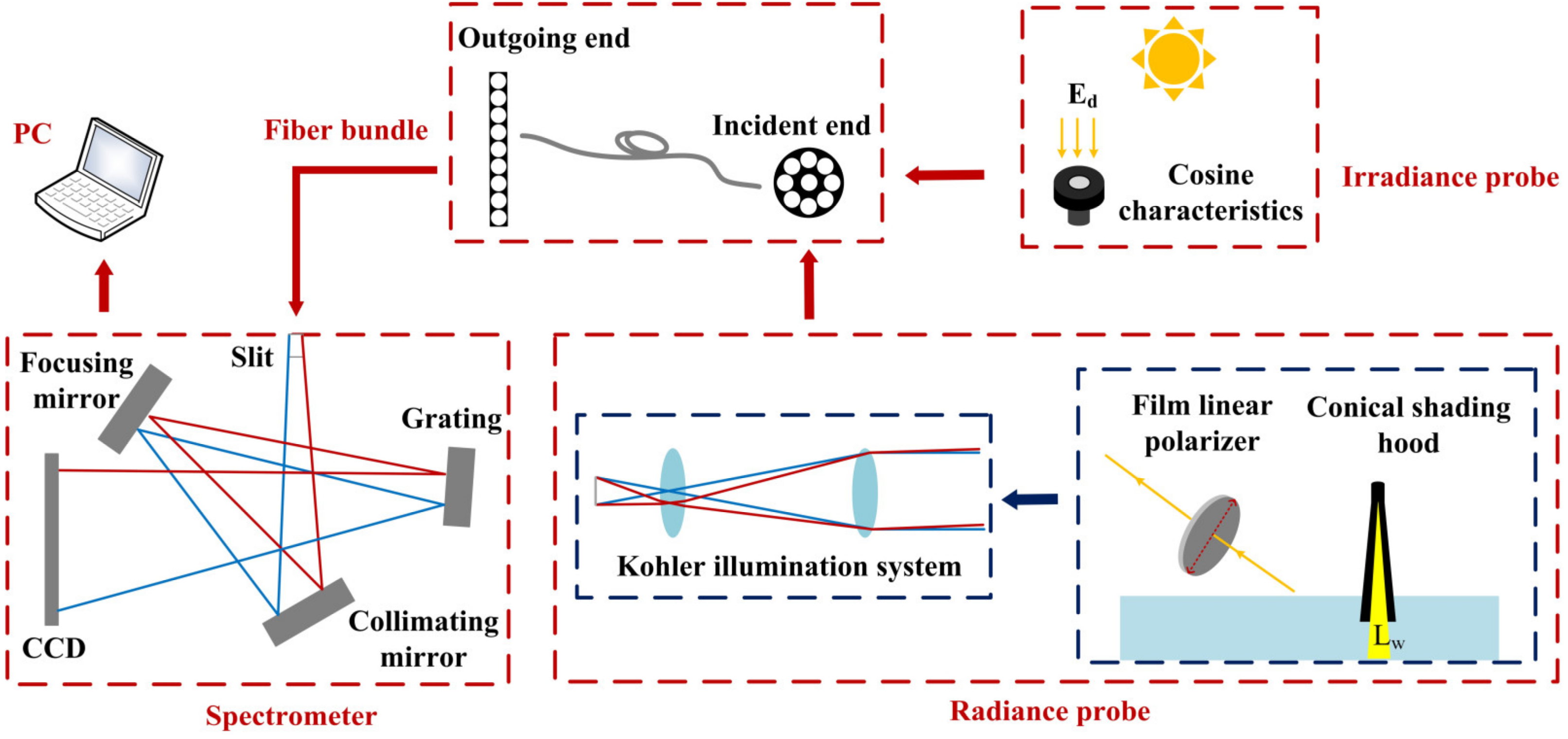
The overall architecture of the PMHRS is illustrated in
Figure 2, which is primarily composed of two modules: the spectral detection module and the front-end optics. The front-end optics are equipped with irradiance detection probes and radiance detection probes. The radiance detection probe is subdivided into three types: the Kohler illumination system (M99 probe), the combination of the Kohler illumination system with a linear polarizer (polarization probe), and the combination of the Kohler illumination system with a conical light shield (SBA probe). The upwelling radiative signal from the water surface is directed into a fiber bundle via a pre-stage radiance probe and then transmitted to the spectrometer slit through the fiber bundle. The light is dispersed according to wavelength across different detector pixels using a collimating lens, a plane reflection grating, and a focusing lens. Data storage and display are subsequently managed by the host computer. The downwelling radiative signal below the water surface is collected by an irradiance probe following the same sequence. To enhance the system’s signal-to-noise ratio and minimize measurement errors caused by target variations, the PMHRS system employs a fiber bundle and Kohler illumination to optimize the integration time. The following sections provide detailed descriptions of the energy comparison analysis before and after fiber shaping, cosine response analysis of the irradiance probe, design of the radiance probes, laboratory radiometric calibration of the entire system, and temperature correction.
2.1. Spectral Detection Module
The spectral detection module utilizes a high-sensitivity spectroradiometer manufactured by Ocean Optics, employing an internal Czerny-Turner optical design. It covers a spectral range from 400 to 1100 nm with a slit size of 100 μm × 1 mm, achieving a spectral resolution of 3–4 nm. The entrance of the slit spectrometer features a rectangular slit. Traditional single-core optical fibers would result in significant energy loss during transmission. The PMHRS employs shaped optical fiber bundles to enhance the filling factor and energy efficiency of the entrance slit, thereby increasing the signal level by several orders of magnitude.
Figure 2 illustrates the dual-end arrangement of a multi-core circular-to-linear conversion optical fiber bundle. The optical fiber bundle is selected with a single-core diameter of 100 μm to match the width of the entrance slit, an outer diameter of 110 μm, and consists of 9 cores to match the length of the slit. The numerical aperture of the optical fiber bundle is 0.37, allowing spectral response across the range of 350 to 2400 nm.
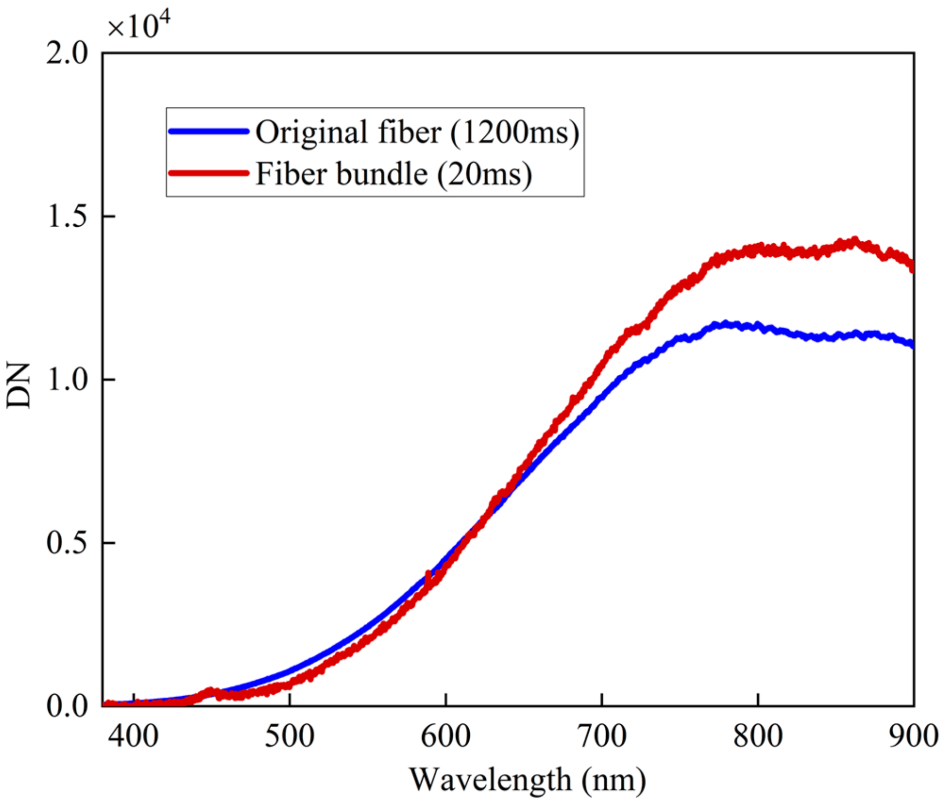
The energy enhancement effect of fiber bundle shaping is verified using a tungsten halogen lamp with an integrating sphere as the target in the laboratory. The results are shown in
Figure 3. For the same target light source, the shaped fiber bundle required only 20 ms of integration time to achieve the DN value of the unshaped fiber (with a single core diameter of 200 μm and an NA of 0.22) at an integration time of 1200 ms. This significantly improves the system’s energy utilization efficiency and ensures the intensity and stability of the radiation signal received by the system.
2.2. Front-End Optics
The front-end optics consist of radiance detection probes, M99 probes, polarization probes, and SBA probes, coupled with optical fibers and spectrometers. These components utilize a common dispersion module to achieve multiplexed signal acquisition for multiple targets. According to the cosine law of irradiance, when sunlight is incident on the detection plane, the irradiance is related to the incident angle and changes according to the cosine law [
27]. Therefore, we select the cosine corrector with cosine response characteristics as the irradiance probe to measure the radiation from the entire hemisphere space, that is, the downward irradiance of the water surface [
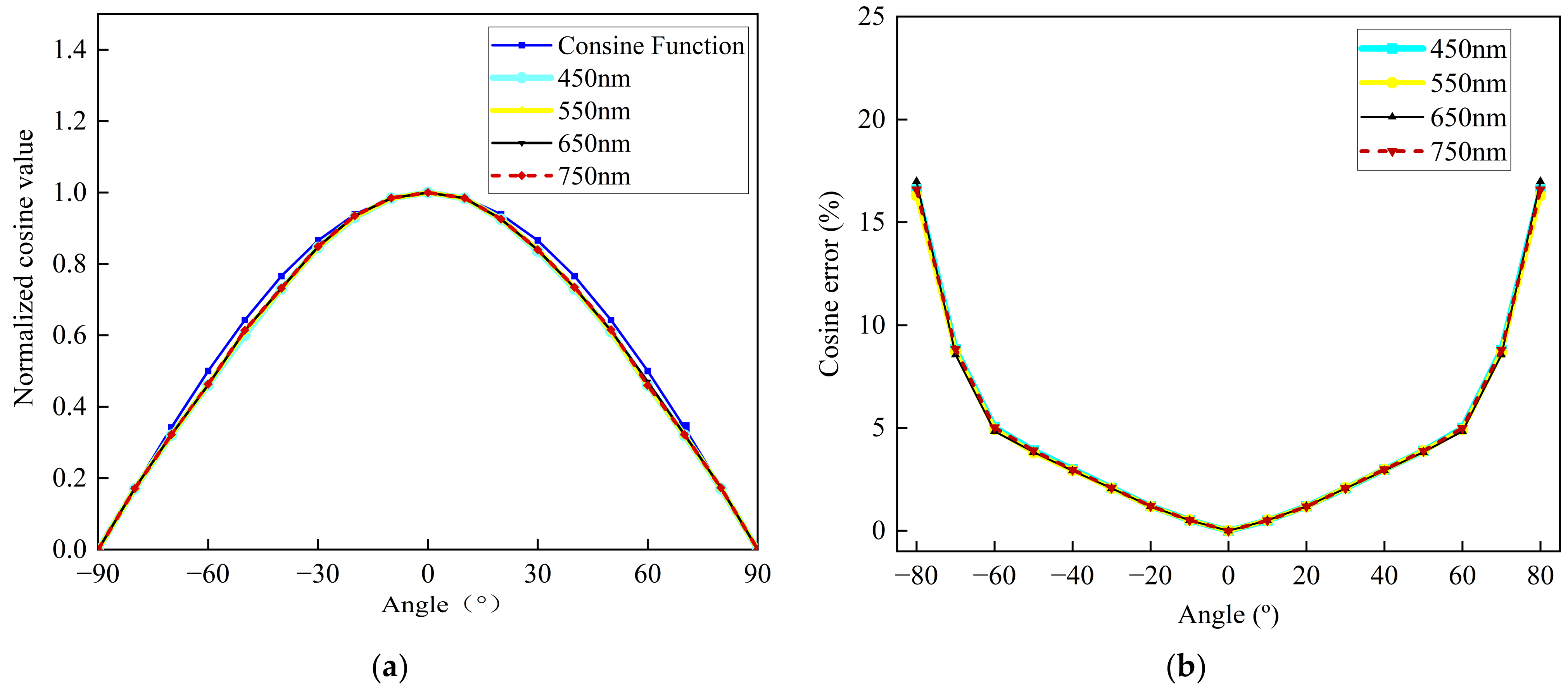
28]. The measurement accuracy of the downward irradiance on the water surface is characterized by the deviation between the angle response function of the cosine corrector and the ideal cosine function. A standard lamp and an electronically controlled turntable are used to collect the signal every 10°, and the cosine error (θ) is calculated according to Formula (3):
where the angle θ represents the angle between the incident light and the normal to the surface, DN(θ) denotes the sensor’s count value when the incident direction makes an angle θ with the normal, and DN(0) represents the sensor’s count value when the incident direction is normal to the surface.
The cosine characteristic curve and cosine error of the irradiance probe are depicted in
Figure 4. Test results indicate that within ±40°, the relative error of the standard cosine values is within 3%. As the angle increases, the relative error gradually rises, reaching 5% around ±60°. The overall root mean square error is less than 0.02189, which is close to the standard cosine curve, demonstrating the excellent cosine characteristics of the irradiance probe in the water spectral reflectivity measurement system.
The irradiance detection probes in the front optics (see physical setup in
Figure 2) are equipped with Kohler illumination systems. This ensures uniform imaging of targets with uneven brightness or prominent filament structures onto the slit [
29], thereby significantly enhancing the system’s energy efficiency. To enhance the overall polarization of the water surface glint within the FOV during polarization measurements, a half-FOV angle of 3° is selected as the design criterion. This angle aligns with the standards for sensor FOV angles specified in marine optical guidelines (2°–18°).
As shown in
Figure 5, the Kohler illumination front optical system consists of objective lens L1 and field lens L2 [
30]. In the figure, θ represents the half-field angle, U is the angle between the chief ray of the edge field and the optical axis, α denotes the angle between the edge ray and the optical axis, ƒ and ƒ′ are the focal lengths of the objective and field lenses, respectively, D is the entrance pupil diameter, and d is the image height. The geometric relationships are defined as follows:
To improve energy efficiency, U should be aligned with the numerical aperture angle of the optical fiber bundle.
To improve the image quality on the focal plane, a combination of two lenses is used to form the field lens. In ZEMAX, the angle between the chief ray of the marginal field and the optical axis is controlled to not exceed 21.7°. The final optimized optical parameters of the three lenses are shown in
Table 1.
The distance between Lens 1 and Lens 2 is 47 mm, between Lens 2 and Lens 3 is 0.93 mm, and the distance from Lens 3 to the image plane is 5 mm. The three-dimensional structure of the optimized Kohler illumination system is shown in
Figure 6.
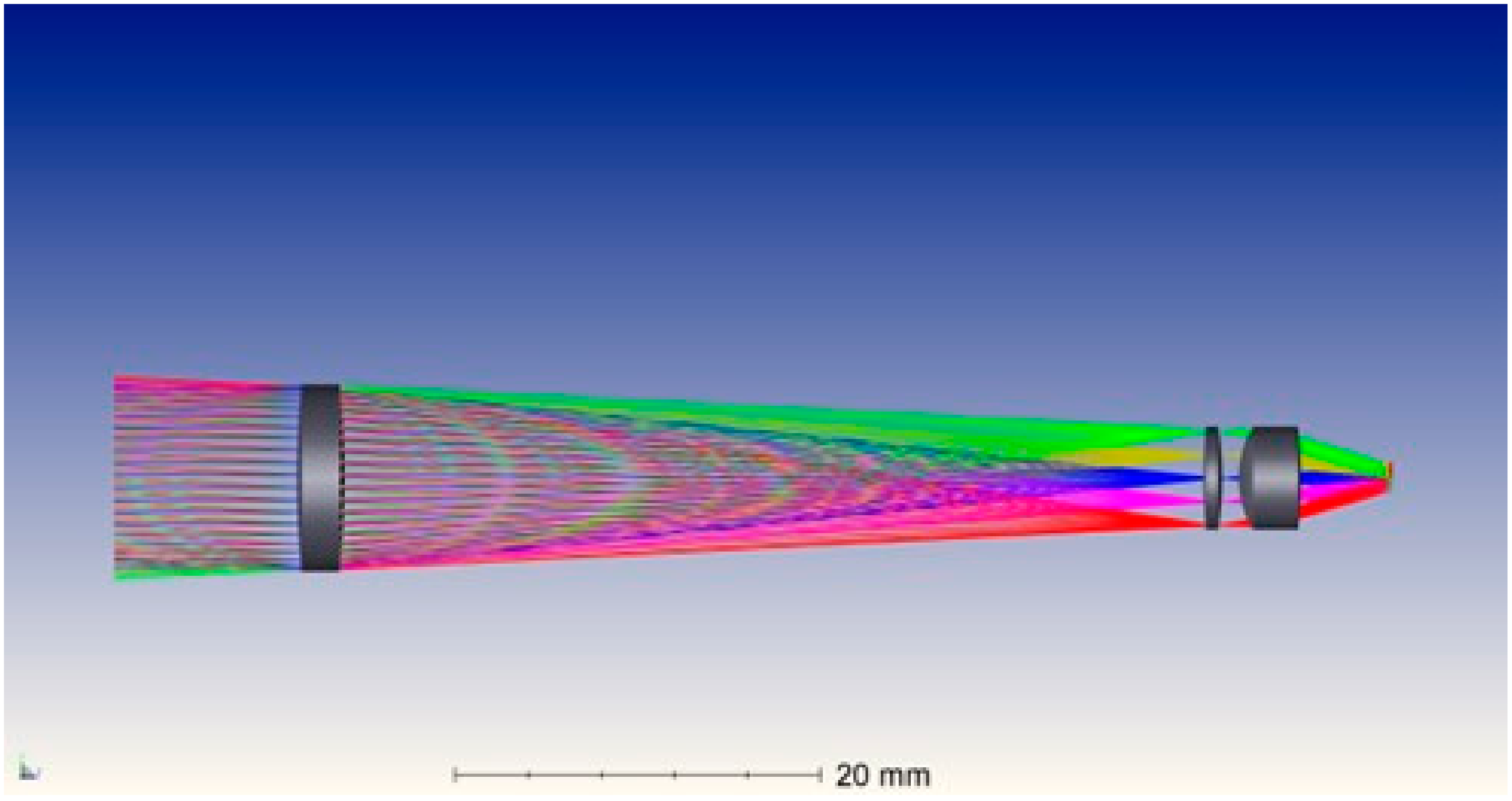
Figure 7 and
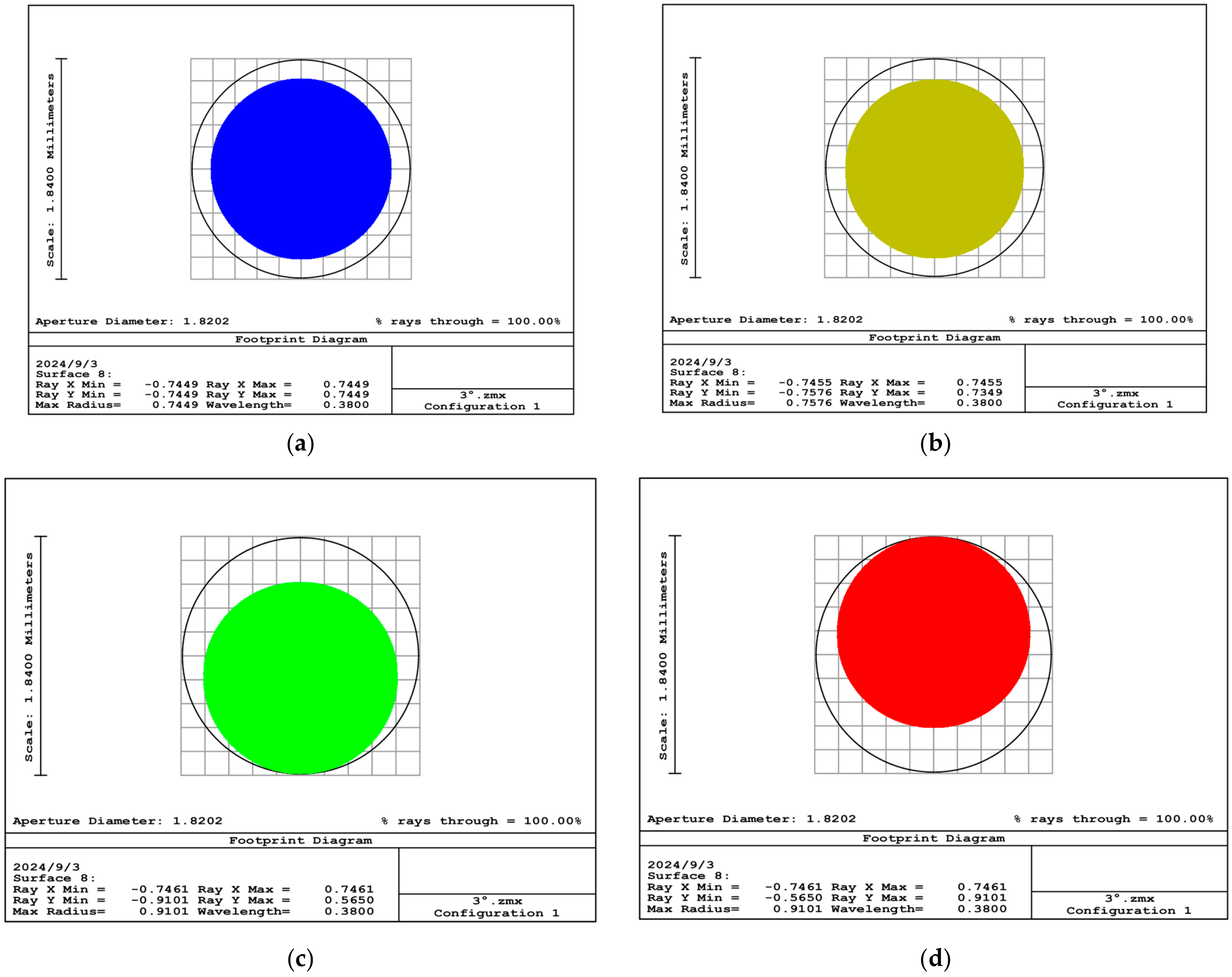
Figure 8 illustrate the ray trace and the image plane energy distribution of the Kohler illumination system, respectively. Within a ±3° FOV, the light spots on the image plane are confined to a circle of 1.84 mm in diameter, with the energy predominantly concentrated within a circular region of 0.8 mm in diameter. The incident end face of the fiber bundle can receive radiation from the entire FOV.
The M99 probe uses the Kohler illumination system to measure water radiance and corresponding sky radiance at specified observation zenith and azimuth angles (φ = 135°, θ = 40°), aiming to remove the water glint. The polarization probe involves placing a linear polarizer at the front end of the Kohler lens, equipped with an external 360° rotation scale, to measure radiance values under two polarization states (0° and 90°), effectively removing water glint. The SBA probe features a conical shading hood at the front end of the Kohler lens to prevent the surface glint from entering the instrument’s FOV. The conical shade, with dimensions of 160 mm height, 14 mm top diameter, and 36.38 mm bottom diameter, has a wall inclination angle of 4°, slightly greater than the Kohler illumination lens’s half-FOV. Both the inner and outer surfaces of the shading cone are coated with black paint to suppress the stray light. The upper end screws into the radiance probe via threads, and the entire assembly is supported by a slender black rod placed in the water, positioning the waterline approximately halfway up the shading cone. Compared to buoy-based deployment methods, the handheld black rod solution addresses real-time variations in the instrument’s floating posture during measurements, while minimizing the buoy’s impact on the underwater light field observed within the FOV.
2.3. Laboratory Radiometric Calibration and Temperature Correction
Radiometric calibration is essential for water surface remote sensing reflectance monitoring instruments, as it ensures the accuracy and consistency of measurements, mitigates environmental influences, enhances the stability and reliability of instruments, and supports high-quality data analysis and applications [
31]. Laboratory absolute radiometric calibration is a process that establishes a quantitative relationship between the output signal of a detector and the actual radiance of the corresponding target of the detector [
32]. This process includes both irradiance and radiance calibration. The schematic diagram of the laboratory radiometric calibration setup is shown in
Figure 9a. The calibration light source uses a spectral irradiance standard lamp F1017, traceable to the national spectral irradiance standard, covering a measurement range of 250 to 2500 nm, with an uncertainty of 0.8–1.0% (k = 2). The standard diffuse reflectance panel is calibrated by the National Institute of Metrology (NIM) of China with a calibration uncertainty of 0.7% (k = 2), and a reflectance of 99%.
Uncertainty analysis of laboratory calibration is essential for assessing the absolute radiometric measurement capability of the water spectral measurement system. The uncertainty primarily arises from the calibration light source, diffuser, and the measurement uncertainty of the instrument itself. The source radiance uncertainty is obtained from the NIM. The instrument measurement uncertainty includes stray light effects, calibration distance errors, measurement stability, and linearity errors of the water spectral measurement system itself [
33]. After effectively controlling environmental stray light in the laboratory and suppressing stray light from the water spectral measurement system itself, the residual stray light impact is approximately 0.32%. Based on multiple measurements using a laser rangefinder, the uncertainty introduced by the calibration distance is about 0.4%. Considering the results of linearity testing of the PMHRS, the measurement uncertainty is approximately 0.54%. The uncertainties are detailed in
Table 2. Since the standard calibration diffuser was used during the laboratory radiance calibration, the combined uncertainty of the radiance calibration includes the uncertainty associated with the diffuser in addition to the uncertainty from the irradiance calibration. The combined uncertainty of the laboratory calibration of PMHRS is ultimately 1.29–1.43% for irradiance calibration and 1.47–1.59% for radiance calibration. Specifically, the laboratory absolute irradiance calibration uncertainty is less than 2% and the radiance calibration uncertainty is less than 3% [
34].
Due to the aforementioned laboratory calibration of spectral radiance conducted at a room temperature of 25.4 °C, discrepancies between the ambient temperature in field experiments and the laboratory calibration temperature can significantly impact the accuracy of water spectral measurements. We investigated the influence of different environmental temperatures on spectral radiance measurements using a simulated experimental setup, as depicted in
Figure 9b. The setup consists of a temperature-controlled chamber, a spectral radiance standard lamp (F1017, 1000W), a diffuse reflectance panel, an aperture, and baffles. The spectroradiometer is placed inside the temperature-controlled chamber, with temperatures set sequentially between 25.4 °C and 40 °C in five equal increments. After stabilizing the chamber temperature for 40 min each time, the working temperature is monitored using a platinum resistance thermometer. The entire experiment is conducted in a dark environment to minimize environmental stray radiation, incorporating apertures and baffles into the optical system. Each experimental group employs the same integration time, and dark signals are subtracted. Results indicate that when the ambient temperature varies from 25.4 °C to 40 °C, deviations in radiance measurements range from approximately ±5% within 400–1000 nm and up to 10% within 380–400 nm.
The calibration coefficients are temperature-corrected using the polynomial fitting method [
35]. The spectral responsivity of a particular detector pixel (wavelength) varies at different temperatures, and the temperature-induced variation ratio I
T/I
cal is fitted to a polynomial function f, described by the following relationship:
In the equations, I
T represents the spectral response of the spectrometer at different temperatures, and I
cal denotes the spectral response at the calibration temperature. a
0, a
1, a
2, …, a
k are the temperature effect coefficients of the spectrometer. The matrix of temperature effect coefficients at different wavelengths is denoted as A (where m is the number of pixels, and n is the order of the polynomial function).
The response of each pixel of the detector at temperature T is represented as follows:
The response corrected for different temperatures is represented as follows:
To validate the applicability of this correction method to the system, calibrated coefficients obtained at 37 °C are compared with those obtained at room temperature after performing a third-order polynomial fit using the aforementioned method. The results demonstrate a significant reduction in deviation compared to the calibration values, with deviations decreasing from 5% to 1% within 400–1000 nm, greatly enhancing the environmental adaptability of the PMHRS.
2.4. Outfield Testing
Field testing is crucial for assessing the performance and reliability of the PMHRS under practical application scenarios. This section outlines the methods of field experiments conducted to validate the system’s capabilities. The field experiments were carried out in coastal waters to evaluate the PMHRS’s performance in measuring water and sky radiance, as well as to test the effectiveness of the glint removal techniques. The testing setup involved the water bodies of Xianghai Reservoir and Songhua Lake, along with the PMHRS deployed using a handheld black rod.
The Xianghai Reservoir is located in Xianghai Mongolian Township, Tongyu County, Baicheng City, Jilin Province. It is 67 km away from Tongyu County. The reservoir bank stretches 50 km in length, with a water surface area of 71 square kilometers. It has a total storage capacity of 210 million cubic meters, an average water depth of 3.5 m, and a maximum depth of 10 m. The primary functions of the reservoir include flood detention and providing water resources for the Xianghai National Nature Reserve, as well as replenishing the Xinglong and Shengli Reservoirs downstream.
Songhua Lake is situated on the western side of the mountainous region in eastern Jilin Province, on the upper reaches of the Songhua River, and 14 km southeast of Jilin City. The lake serves multiple functions including providing drinking water, power generation, flood control, irrigation, shipping, aquaculture, and tourism. It is a crucial water supply source for Jilin City and Changchun City. Considering the dynamic changes in water quality in these two bodies of water, many scholars have recently conducted remote sensing research on the inversion and monitoring of chlorophyll and suspended particulate matter concentrations. However, there has been little exploration of high-resolution water body measurements.
On 2 May 2024, field experiments were conducted at coordinates (122.2865° E, 45.3478° N) as shown in
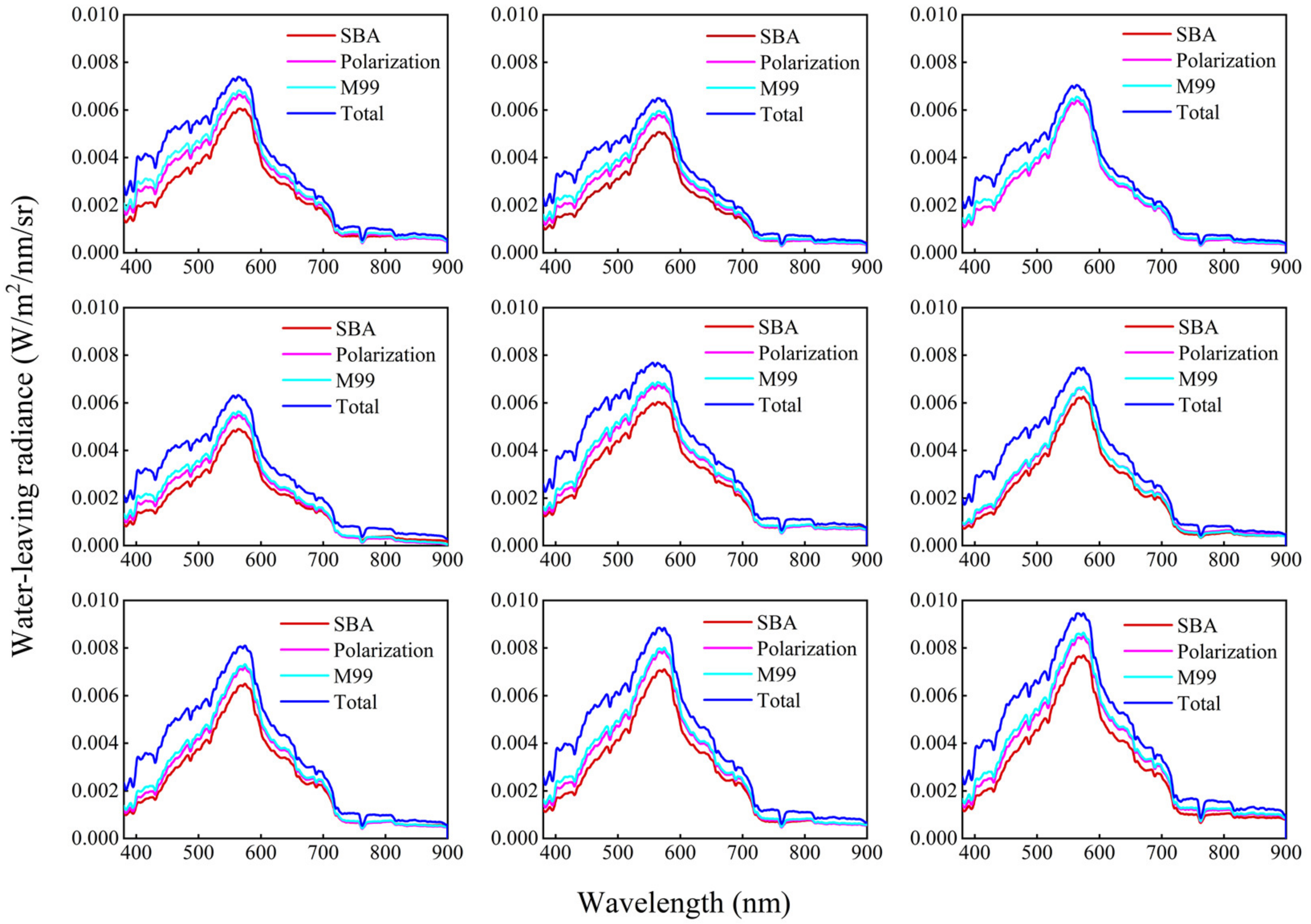
Figure 10. On 25 June 2024, measurements of off-water radiance were conducted at 9 different stations around Songhua Lake, as depicted in
Figure 11, using the M99 method, polarization method, and SBA method. As shown in
Figure 12a,b, water spectral data were simultaneously collected using the PMHRS and the internationally recognized ASD FieldSpec 4 Hi-Res portable spectrometer. The collected measurements were cross-validated against L2A-level Sentinel-2B data corrected by Sen2cor atmospheric correction. The SBA method is shown in
Figure 12c. These measurements aimed to study the effectiveness of removing water glint under various solar elevation angles.
4. Discussion
Calculating appropriate Rrs spectra is a challenging task. Glint removal methods are commonly applied across various oceanic and freshwater environments; however, there is no clear agreement on which method is the most effective. When using remote sensing reflectance measurements from different sensors on the same water target as a standard to evaluate the effectiveness of various sun glint removal methods, several significant issues arise. Firstly, discrepancies in the intrinsic response of different sensors and their varying sensitivity to temperature can introduce errors into the experimental results. Secondly, the FOV of different instruments is not strictly consistent, which means that the effectiveness of glint removal is not solely determined by the experimental method itself; instead, the instrument’s FOV also acts as a variable that can interfere with the results, leading to inconclusive experimental outcomes.
To address these issues and enhance glint removal effectiveness, thereby improving the accuracy of remote sensing reflectance measurements, this study proposes the PMHRS, which is based on three glint removal methods: the M99 method, the polarization method, and the sky-blocking approach (SBA). Compared to methods proposed in recent studies by other scholars, the PMHRS has several novel features and advantages. Firstly, in terms of measurement flexibility, the system can select an appropriate method according to the specific conditions of the complex field measurement environment. Moreover, the near-synchronous datasets obtained from the three sets of sensors can be cross-validated, thus avoiding result distortion caused by operational errors in the field. Secondly, to solve the issue of prolonged integration time affecting the constancy of the target source within a single measurement cycle during polarized measurements, the PMHRS utilizes the Kohler illumination system and shaping fiber bundles to significantly improve the instrument’s signal-to-noise ratio (SNR) and shorten the integration time. This also plays a crucial role in effectively reducing the instrument’s FOV, thereby enhancing glint removal effectiveness. Lastly, the PMHRS is not only compact and portable but also features a common dispersive, multi-sensor design, which allows for the study and discussion of the applicability of various glint removal methods in different types of water and under different solar zenith angles—an advantage that other sensors do not possess.
Two field experiments were conducted using the PMHRS: the Xianghai Reservoir experiment and the Songhua Lake experiment. The objectives of these two experiments were different. The Xianghai Reservoir experiment focused primarily on assessing the performance improvement of the PMHRS compared to traditional instruments and its level of satellite calibration. The experimental results demonstrate that the PMHRS data perform well in both qualitative and quantitative analyses. Compared to the minor discrepancies observed with ASD, the reasons for these differences are analyzed as follows: the smaller FOV of the system developed in this study, compared to the FOV set for ASD during measurements, and the fact that RrsPMHRS data were collected using the M99 method, which strictly controls the observation geometry (using a level and a two-dimensional angle disc) to minimize the impact of water surface glint. In contrast, ASD measurements lack constraints on the instrument’s observation elevation and azimuth angles, allowing some water surface glint to enter the FOV. This results in stronger contributions from direct sunlight and sky-reflected light in the shortwave spectrum. Differences in the SNR of the instruments introduce varying errors in the weak signal regions below 450 nm and above 700 nm.
The experiment conducted at Songhua Lake primarily focused on evaluating the measurement performance of the PMHRS’s multi-sensor system under different solar zenith angles. Taking advantage of the SBA method’s ability to avoid interference from surface water glint, a deviation analysis was performed by comparing the water-leaving radiance results obtained using the traditional method and the polarization method with those from the SBA method. The results strongly demonstrate the effectiveness of the PMHRS designed in this paper for removing water surface glare, highlighting its advantage of multi-source synergy. Improvements to the shaping fiber bundle and the Kohler illumination front optical system have enhanced the system’s energy utilization rate, reduced the instrument’s FOV, and increased the degree of polarization of water surface glare during polarization measurements. This results in better removal of water surface glare in above-water spectral measurements. Compared to the traditional M99 method, the polarization-based water-leaving radiance measurement method has the advantages of easy operation, and the measurement accuracy is less affected by changes in meteorological conditions. This method does not require changes in observation geometry and can eliminate or weaken the effect of glint on the water surface only through the spectral measurement of the water body. As this method allows for continuous water body measurements, it lays a crucial technical foundation for developing water platforms for continuous high-resolution data observation under complex sea conditions.

