1. Introduction
In recent years, strain sensing has become critically important across various domains, such as health monitoring, bridge construction, aerospace, and civil engineering [
1,
2]. Given this context, optical fiber sensors (OFSs) have been widely proposed. Compared to electrical sensors, OFSs are more applicable in practical applications owing to their unique advantages, like anti-electromagnetic interference, small volume, and light weight. Hence, plenty of fiber structures and methods, like Fabry–Perot interferometers (FPI) [
3], Mach–Zehnder interferometers (MZIs) [
4,
5], long-period fiber grating (LPFG) [
6,
7], and fiber Bragg grating (FBG) [
8], are being proposed and experimentally tested. Among them, strain sensors based on MZIs have become a research hotspot in recent years due to their high sensitivity and flexible design approaches. Compared to FBG and LPFG, sensors based on MZIs offer the advantages of simplicity in fabrication techniques and diversity in manufacturing methods. Additionally, the characteristic multiple resonance peaks of the MZIs facilitate multiparameter measurement [
9]. The initial fiber-optic MZI featured two independent arms, a reference arm and a sensing arm, connected by two 3 dB couplers [
10]. After passing through the first coupler, light is coupled with both the sensing and reference arms. When a tensile load is applied to the sensing arm, a change in the optical path difference between the two arms occurs, causing a spectral shift upon the re-coupling of the two beams of light. With continuous advancements in fabrication technologies, the integration of MZIs into the fiber has been realized [
11]. For instance, MZIs based on fiber assembly techniques [
12], tapering technologies [
13], and core bending have been developed [
14]. Among these options, core bending technology has attracted widespread attention due to its straightforward fabrication process and lower use costs.
The bending of the fiber core is commonly achieved by heating and softening the op-tical fiber, such as by misaligning and clamping the fiber between two fixtures of a fusion splicer and applying heat [
15], thereby obtaining a bent fiber structure. However, this method results in poor repeatability. As an alternative, the symmetric structure of the fiber is broken before heating. When heated and stretched, the cladding is deformed under the action of balancing forces, and the core is simultaneously bent [
16]. However, this method induces significant residual stresses within the structure, making it highly susceptible to fracture when subjected to radial forces. Therefore, high-sensitivity S-shaped core MZI strain sensors, with better repeatability and structural strength, are worth studying.
Here, we propose and implement an S-shaped core MZI that is capable of simultaneously monitoring temperature and strain. By means of the side-polishing method, two staggered V-shaped grooves are formed on the symmetrical surface of an SMF. Then, the polished area is placed under arc-discharging conditions. Upon exposure to arc heating, the etched region of the optical fiber cladding recovers to a circularly symmetric structure, while the fiber core bends in response to the alteration in the cladding shape. Two S-shaped cores (SSCs) are constructed, with one designated as a beam splitter and the other as a coupler. When the input light enters the first S-shaped core (SSC), it is coupled with the cladding and subsequently re-coupled with the core at the second SSC. The analysis of the experimental data indicates that the sensor proposed achieves a high strain sensitivity, reaching up to −66.5 pm/με and −40.1 pm/με within a strain range from 0 με to 350 με. The temperature characteristics are also experimentally analyzed and the temperature sensitivities are 58.8 pm/°C and 53.3 pm/°C. By solving the matrix equation, the proposed sensor can be applied for the simultaneous measurement of strain and temperature. Thus, it is believed the SSC−MZI is applicable in strain sensing, with the advantages of high sensitivity and a compact size of 5 mm.
2. Principle and Simulation
The configurations of the SSCs are presented in
Figure 1 and they are designated, respectively, as the beam splitter and the coupler. As the input light transmits into the SSCs of the first one, it is separated and coupled back at the SSCs of the second. Owing to the bent core, a segment of the light energy is transferred to the cladding. As a consequence, an MZI based on the core-cladding interference is realized. According to the theory, the interfering intensity of the SSC−MZI can be expressed as follows [
17]:
where
is the intensity of core mode,
is the intensity of the cladding mode, and
is the phase difference between the core mode and cladding mode. This can be described as follows:
where
is the wavelength drift, and
and
are the effective refractive indexes of the core mode and the
m-th cladding mode, respectively. In Equation (2),
is an integer and
is the length of the interference. By solving Equation (2), the wavelength corresponding to the
m-order dip can be defined by
where
is the effective refractive index difference between the core mode and cladding mode. Therefore, the free spectral range (FSR) of the SSC−MZI can be estimated and approximated to the equation below through the application of Taylor expansion:
Based on Equation (4), the FSR of the structure exhibits an inverse proportionality to the length of the interferometer when the wavelength
remains constant. Therefore, the FSR can be appropriately adjusted by varying the length of the interferometer. The contrast K of interference fringes is expressed as follows:
By analyzing the Equation (5), it is deduced that the contrast of the spectrum fringes is influenced by the intensity of light propagating through the fiber’s cladding and core. Therefore, the maximum value of is achieved when .
The strain sensitivity S of the SSC−MZI can be obtained by calculating the partial derivatives at both ends of Equation (3) [
18]:
For the proposed SSC−MZI, with the aid of the bending cores embedded in the SSCs, the deformation of the SSC substantially modulates L and . When tensile strain is exerted symmetrically onto the sensor, there is a progressive reduction in the extent of core bending. This alteration leads to changes in the optical mode coupling to the cladding, inducing a decrease in the energy effusion from the fiber core. In a word, when the SSC is subjected to axial strain, the optical mode and light intensity of the fiber core coupled to the cladding will change, resulting in a change in . Therefore, the SSC−MZI can be employed to detect the axial strain.
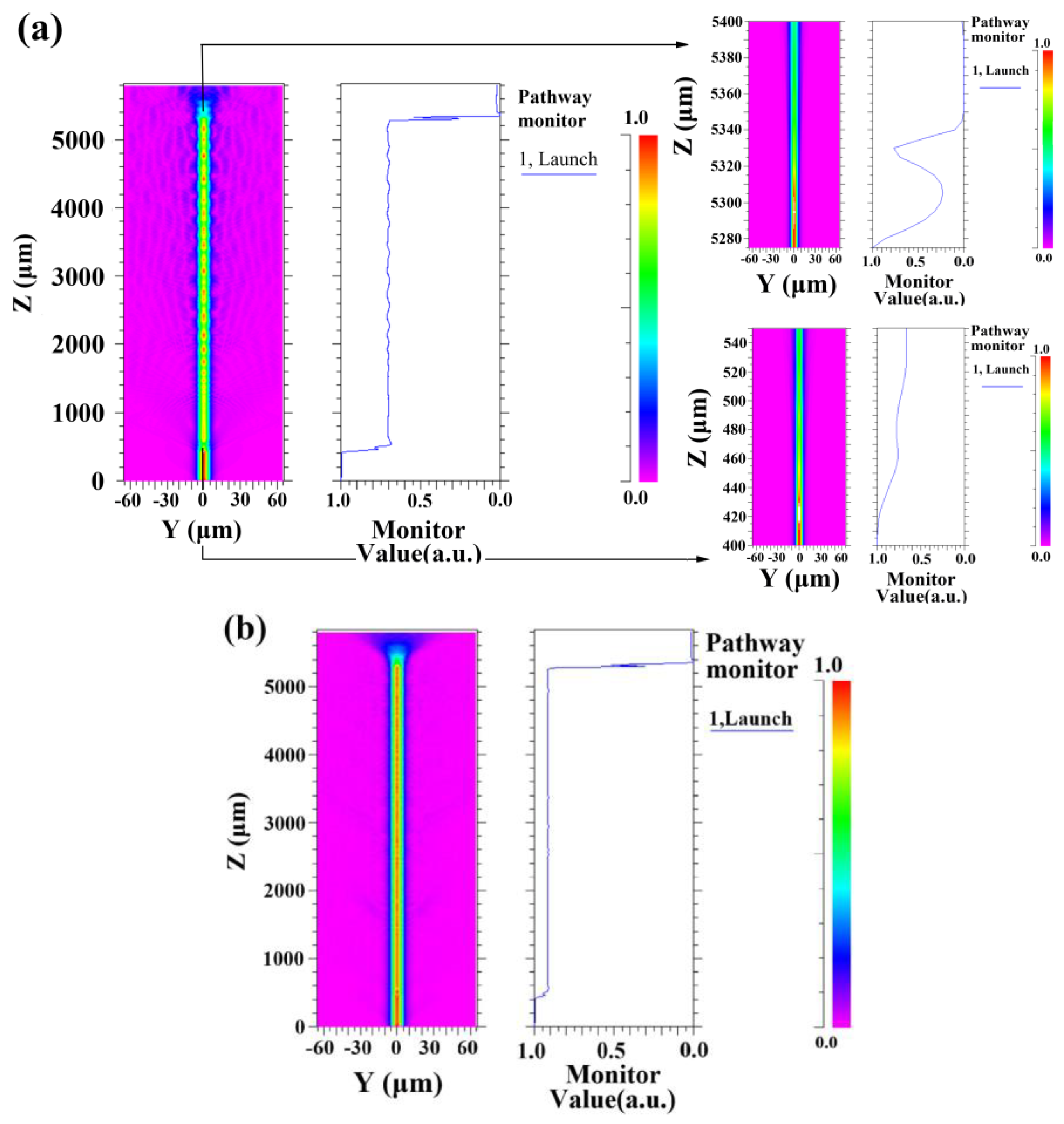
To clarify whether the light transmitted to the fiber core can be coupled with the cladding, the light field distribution and the light transmission of the proposed structure are simulated [
19] using the beam propagation method, which is presented in
Figure 2a. The relevant parameters are set as follows: the cladding and core diameters are 125 μm and 8 μm, respectively. The core exhibits a maximum bending deviation of 5 μm. The separation between the two SSCs is 5 mm, and the length of the core bends is established at 105 μm. Besides, bent deviations of SSCs are adjusted to a smaller value to model the light field distribution under stress conditions, as shown in
Figure 2b, which confirms a reduction in the light intensity of the cladding.
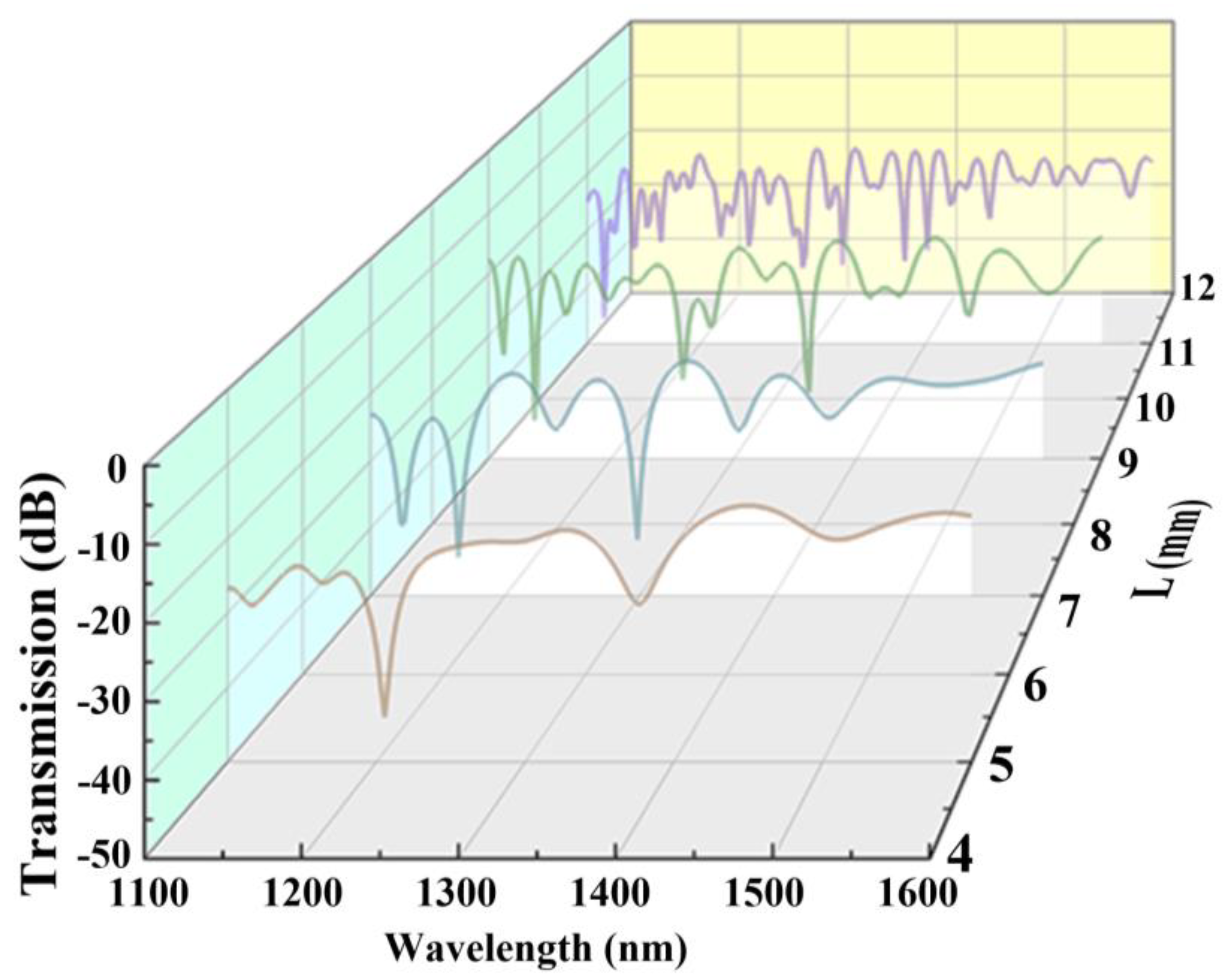
Furthermore, to investigate the influence of the length of interference on the transmission spectrum, models with interference lengths of 5, 7, 9, and 11 mm are established for simulation by employing the above-mentioned method, which is represented in
Figure 3. In order to ensure that, during the discharging of one SSC, the other SSC is not affected by the electrode, the distance between the two SSCs is controlled to be over 5 mm. Referring to Equation (4), the FSR is inversely proportional to the interference length. Furthermore, with the increase in
L, there is the consistent formation of additional cladding modes, which accumulate a significant phase difference compared to the fundamental mode. These modes are re-coupled to the core at the second SSC, where they interfere with the fundamental mode. Therefore, an SSC−MZI with an extended transmission region leads to a more irregular spectral formation, and a reduction in spectrum contrast occurs due to the energy dissipation of the dominant cladding mode. The designed SSC−MZI is expected to be used for a high-sensitivity strain sensor, and a substantial FSR with elevated contrast is essential. Therefore, samples with interference length of 5 mm are chosen for further investigation.
3. Method
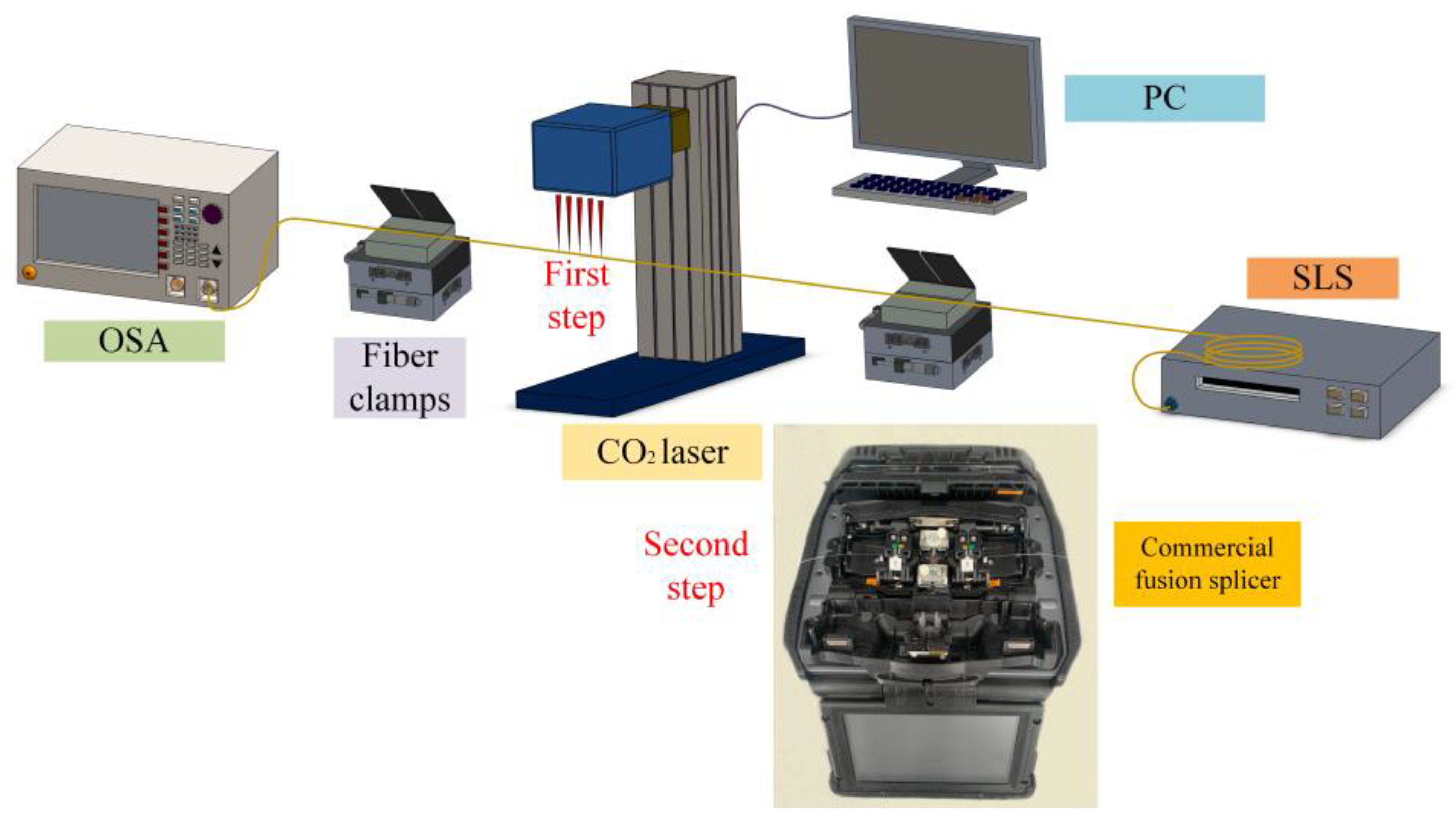
The fabrication process of the structure is straightforward and consists of two stages: polishing and arc-discharging. Firstly, the PC-controlled CO
2 laser is activated and the experimental setup is illustrated in
Figure 4. In the manufacturing process, a section of SMF is fixed with two rotating clamps. The two ends of the SMF are connected to a super-continuous light source (SLS) and an optical spectrum analyzer (OSA) to monitor changes in the transmission spectrum in real time. Two three-dimensional displacement platforms are adjusted to ensure the accuracy of the fiber polishing. The specific polishing parameters of CO
2 laser are set as follows: maximum power: 30 W; power setting: 16% (~4.8 W); laser frequency: 50 kHz; scanning speed: 500 mm/s; and optical wavelength: 10.6 μm.
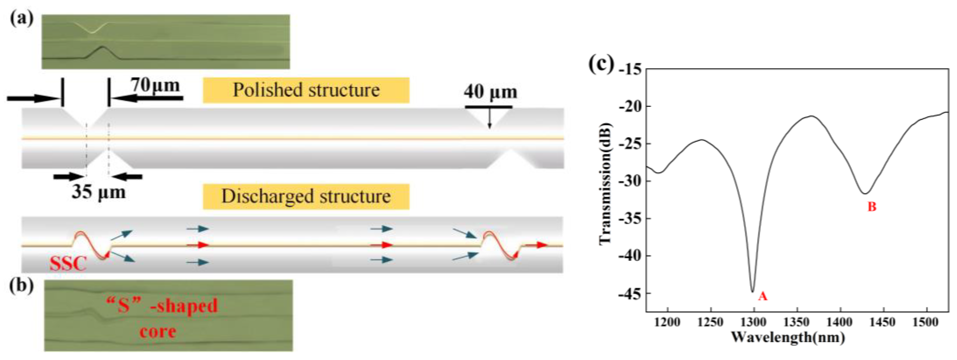
The specific polishing procedures are designed through the computer. In this method, the V-groove is engraved onto one side of an SMF [
20], where the etched depth and width of the V-groove are 40 and 70 μm, respectively. Then, the structure is rotated 180° and the second procedure is utilized to polish the same V-groove. The axial shift between the two staggered V-grooves is 35 μm, which is presented in
Figure 5a. With the same method, the structure is also prepared 5 mm away from this set of grooves. Thus, a pair of two V-shaped grooves is prepared. Secondly, the polished structure is fixed within a commercial fusion splicer (Fujikura FSM-60S) for further modulation [
21], which is shown in
Figure 4. By monitoring the screen of fusion splicer, the position of the staggered V-shaped grooves can be adjusted until the structure is completely within the scope of the heating. Then, a pair of grooves is discharged with an advancing stepping motor and another remains constant. During the discharging process, the cladding of the fiber melts and reassembles rapidly under the discharging process, becoming a relatively flat surface due to the surface tension effect. Meanwhile, the core in the fiber is bent with the deformation of the cladding. By employing the same method, every groove is discharged. After the discharging process, the geometric appearance of the polished SMF is reshaped as described in
Figure 5b, and the spectrum of the proposed structure is displayed in
Figure 5c. For Dip A and Dip B, the transmission dip is 1298.2 nm and 1428 nm, respectively. The difference between the simulated results and the actual spectral structure is primarily due to deviations in the discharge process. During the fabrication of the SSC−MZI, the etching of the fiber cladding by the CO
2 laser is controlled by computer programs, and the splicer used in the experiments is a commercial fiber fusion splicer, which offers high arc stability and displacement accuracy, ensuring the same degree of core bending in the samples. The high precision and automation of the manufacturing equipment ensure the repeatability and feasibility of SSC−MZI fabrication.
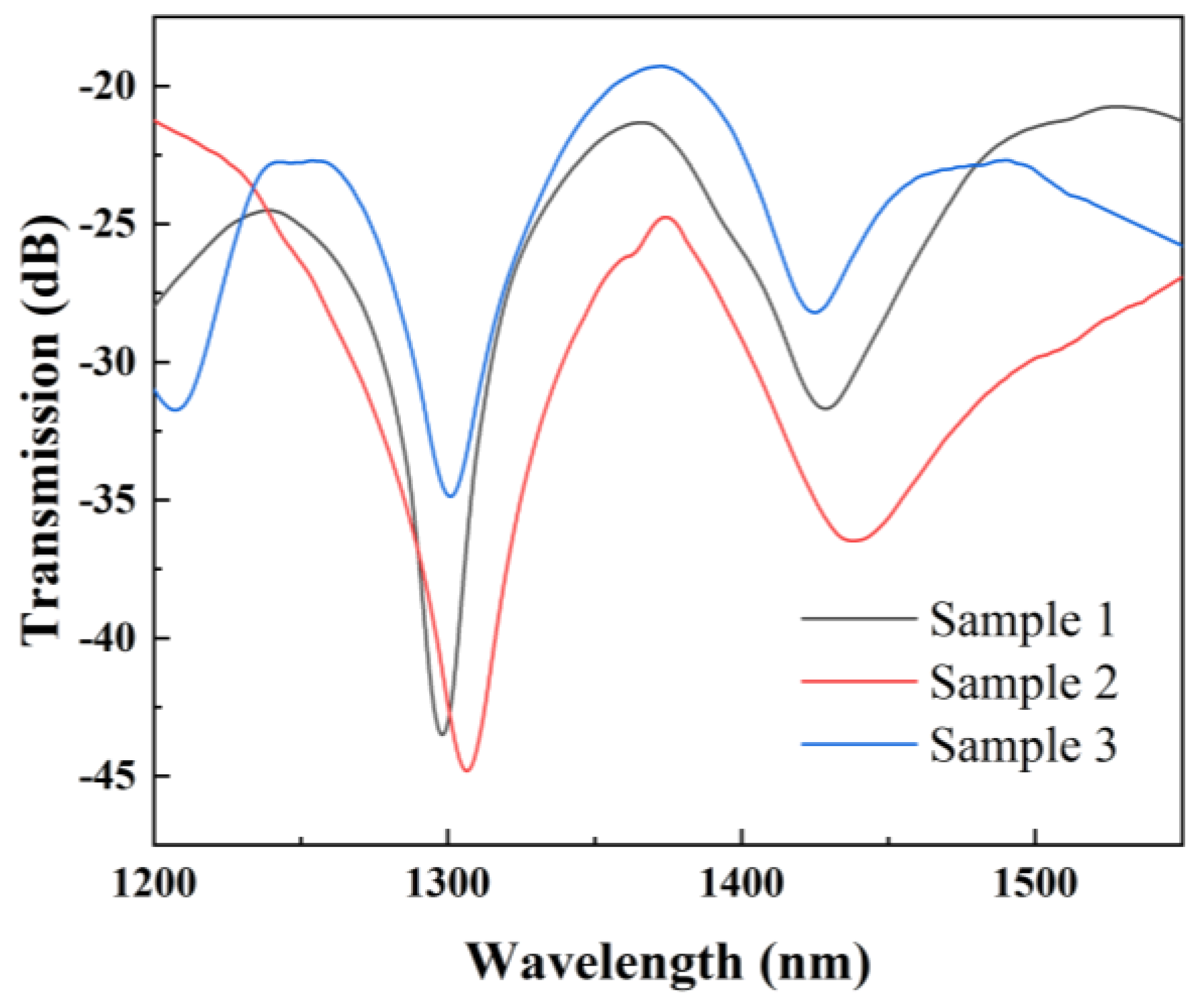
Figure 6 shows the Spectral comparison of three SSC−MZIs with identical parameters. It can be seen that the positions of the resonance peaks of the three samples have high consistency.
4. Result
In the experimental setup, each end of the SSC−MZI is fixed on a three-dimensional displacement stage. By employing the control box, two stepping motors are then moved towards both directions along the structure to obtain the axial strain. The strain value is calculated by , where is the initial distance between the two displacement stages, and is the distance generated by the movement of the stepping motors. Additionally, the light from SLS is coupled with the SSC−MZI and the output spectra are analyzed by the OSA under a resolution of 0.02 nm.
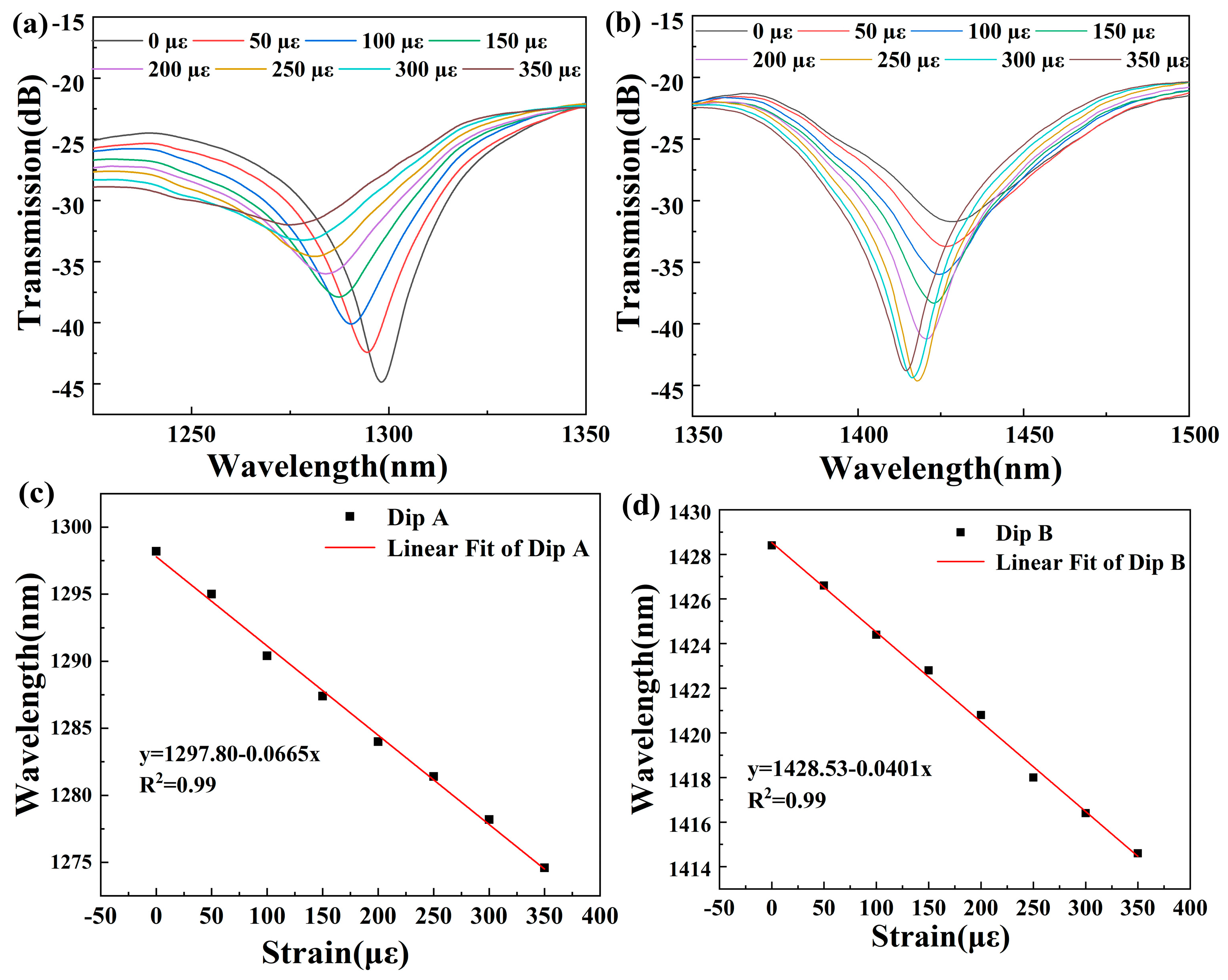
Figure 7 illustrates the shifts in transmission peaks as the applied strain increases incrementally from 0 με to 350 με in steps of 50 με. As the applied strain increases, the extent of core bending decreases, which leads to decreasing
. According to the Equation (3), the resonant wavelength is positive correlated with the
. Therefore, both resonant wavelength of Dips A and B present blue shift. In addition, as the strain increases over 350 με, Dip B disappears, and so the measuring range is controlled as 0–350 με. The correlation between the applied strain and the wavelength shift is characterized by a linear function, as illustrated in
Figure 7c,d. In the range of 0 με to 350 με, the sensitivity is −66.5 pm/με and −40.1 pm/με, with a considerable R
2 of 0.99. Furthermore, the temperature characteristic is also investigated. In the experiment, the sample is placed onto a heating platform and the temperature is raised from 20 °C to 130 °C in increments of 10 °C.
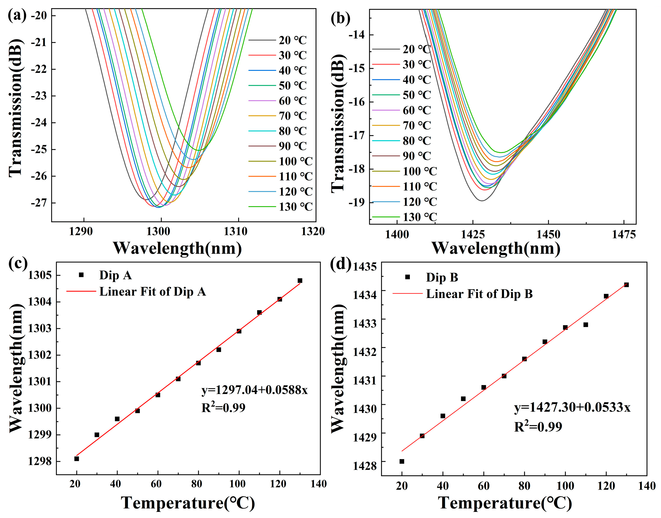
To ensure that the stress on the fiber remains consistent across different temperatures, a standard weight was suspended from the fiber. As illustrated in
Figure 8a,b, both transmission peaks exhibit a red shift.
Figure 8c,d show that the temperature sensitivity of Dip A is 58.8 pm/°C and that of Dip B is 53.3 pm/°C, with the considerable linear fitting degree of 0.99.
Thus, the transmission spectrum of the proposed SSC−MZI exhibits good linearity for both temperature and strain. It can be used for their simultaneous measurement, and the relationship is expressed via the following matrix:
where
,
and
are the strain and temperature sensitivity of two resonance dips, and
and
represent the variations in temperature and strain, respectively.
and
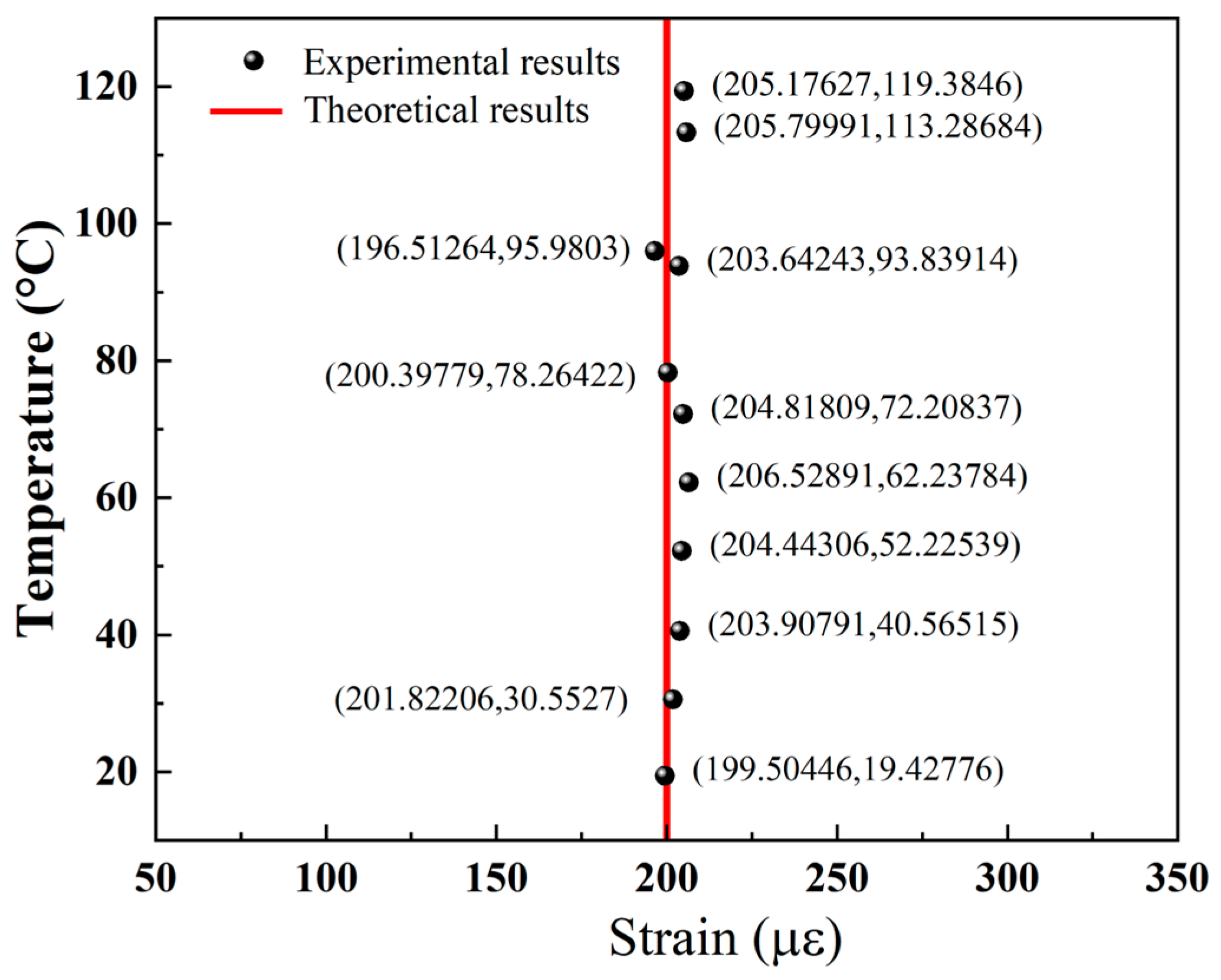
are defined as the wavelength shifts of two dips. To investigate the actual measurement capabilities of the structure for temperature and strain, we subjected it to a condition of 200 με, changed the ambient temperature, and simultaneously measured the changes in wavelength. The experimental data were input into the matrix for calculation, yielding the computed values for temperature and strain. The experimental results are shown in
Figure 9.
As illustrated in
Figure 9, the strain values derived from wavelength calculations are closely aligned with the predetermined actual values.
To highlight the advantages of this method,
Table 1 summarizes the comparison between SSC−MZIs and sensors fabricated based on other processes. As shown in
Table 1, although the measurement range is somewhat limited, the SSC−MZI exhibits significantly higher sensitivity compared to strain sensors fabricated using other manufacturing processes.
5. Conclusions
In this study, a highly sensitive strain sensor based on an S-shaped core MZI (SSC−MZI) was designed and experimentally testified. The SSC−MZI is successfully fabricated by the CO2 laser polishing method and arc-discharging method. By analyzing the simulated results, the most suitable interference length is obtained. When the structure is subjected to axial strain, the degree of core bending displays a strong influence on the effective refractive index of the core mode, and also displays strong influence on light transmission. The experiment’s results indicate that strain sensitivities of −66.5 pm/με and −40.1 pm/με are achieved across a dynamic range from 0 με to 350 με. Additionally, the two transmission peaks also present considerable linear sensitivity to temperature. Therefore, simultaneous measurement of the two parameters can be accomplished through solving the matrix equation. Combining the advantages of low cost, easy fabrication, compact size, and high sensitivity, the SSC−MZI shows wide application prospects in practical measuring.

