Article

Modeling of High-Power Graded-Index Fiber Amplifiers

1
Department of Physics, Indian Institute of Technology Kharagpur, Kharagpur 721302, West Bengal, India
2
The Institute of Optics, University of Rochester, Rochester, NY 14627, USA
*
Author to whom correspondence should be addressed.
Photonics 2024, 11(8), 737; https://doi.org/10.3390/photonics11080737
Submission received: 3 July 2024 / Revised: 2 August 2024 / Accepted: 5 August 2024 / Published: 7 August 2024
(This article belongs to the Special Issue High-Power Fiber Lasers)

Abstract

:
Graded-index fibers have been used in recent years to make high-power fiber lasers and amplifiers. Such fibers exhibit self-imaging, a phenomenon in which any optical beam periodically reproduces its original shape in undoped fibers (no gain). In this work, we employed analytic and numerical techniques to study how self-imaging affects the evolution of a signal beam inside a nonlinear graded-index fiber amplifier, doped with a rare-earth element and pumped optically to provide gain all along its length. We also exploited the variational technique to reduce the computing time and to provide physical insights into the amplification process. We compared the variational and fully numerical results for the two pumping schemes (clad pumping and edge pumping) commonly used for high-power fiber amplifiers and show that the variational results are reliable in most cases of practical interest. The stability of the signal beam undergoing amplification is examined numerically by launching a noisy Gaussian beam at the input end of the amplifier. Our results show that the quality of the amplified beam should improve in the case of edge pumping when a narrower pump beam provides an optical gain that varies considerably in the radial direction of the fiber. Such an improvement does not occur for the clad pumping scheme, for which the use of a relatively wide pump beam results in a nearly uniform gain all along the fiber.

1. Introduction

Graded-index (GRIN) fibers were studied as early as 1970 in the context of optical communications, owing to their smaller differential modal delays compared to multimode step-index fibers [1]. More recently, GRIN fibers have been used to enhance the capacity of telecommunication systems through mode-division multiplexing [2] and for studying intriguing nonlinear effects such as the formation of multimode solutions [3], the creation of dispersive waves over a wide spectral range [4,5], the spatiotemporal mode-locking of lasers [6,7,8], and the generation of a supercontinuum [9,10,11]. Furthermore, Krupa et al. have shown that the nonlinear Kerr effect and periodic self-imaging are the driving mechanisms for the onset of geometric parametric instability [12] and for observing spatial beam clean-up in GRIN fibers [13].
Ytterbium-doped multimode fibers are used extensively when making high-power lasers and amplifiers because of their relatively wide central cores. Recently, the use of GRIN fibers has attracted attention for such amplifiers and lasers. GRIN fibers provide better beam quality compared to step-index fibers, owing to the phenomena of spatial beam clean-up [14,15]. A mode-based analysis shows that GRIN fibers are instrumental in improving the output beam’s quality [16,17]. However, the modal approach becomes less useful for a high-powered fiber amplifier when many modes of the GRIN fiber are excited by the pump and signal beams. By adopting the concept of wave thermalization, it was shown in a recent study that the improvement in beam quality is associated with nonlinear phase locking among the modes of a fiber [18].
Non-modal numerical studies of GRIN-fiber amplifiers have also been carried out in recent years [19,20]. This approach, in general, requires solutions to multidimensional coupled differential equations and is, by necessity, resource-intensive. Even though a detailed numerical analysis may be needed in some situations, more physical insight can be gained by adopting a simpler approach. An approximate analytical treatment used recently [21] ignored an important nonlinear effect known as self-phase modulation (SPM).
Our aim in this study is to develop a numerical model of GRIN fiber amplifiers that includes most of the relevant amplification physics and provides useful results on a relatively fast time scale. Our work is based on a reasonable model for the pump-induced local gain inside a doped GRIN fiber and also includes the relevant nonlinear effects. Further, we consider both the edge and clad pumping schemes and compare them. We also develop a variational approach, used earlier for high-power Raman amplifiers [22], and validate it by comparing its results with those provided by the multidimensional numerical model. We found that in most practical cases, the evolution of an optical beam inside a GRIN fiber amplifier can be modeled much faster by solving a few coupled ordinary differential equations. Our approach provides considerable physical insight and should be useful for designing and analyzing experiments on high-power amplifiers based on doped GRIN fibers.
This article is organized as follows. We present in Section 2 the numerical model we used for studying the amplification of a signal beam, launched into a GRIN fiber amplifier that was pumped optically to produce the optical gain. We also discuss the simplifications that we made to obtain a partial differential equation satisfied by the slowly varying amplitude of the signal beam. We performed a stability analysis in this section to ensure that the amplifying beam maintained its spatial structure. The propagation equation was solved approximately in Section 3 using a semi-analytical variational approach, resulting in four coupled ordinary differential equations describing the evolution of four beam parameters inside the GRIN fiber. These equations are solved in Section 4 for two specific pumping schemes, and the results are compared with those obtained by solving the multidimensional equation numerically. We summarize our main conclusions in Section 5.

2. Theory

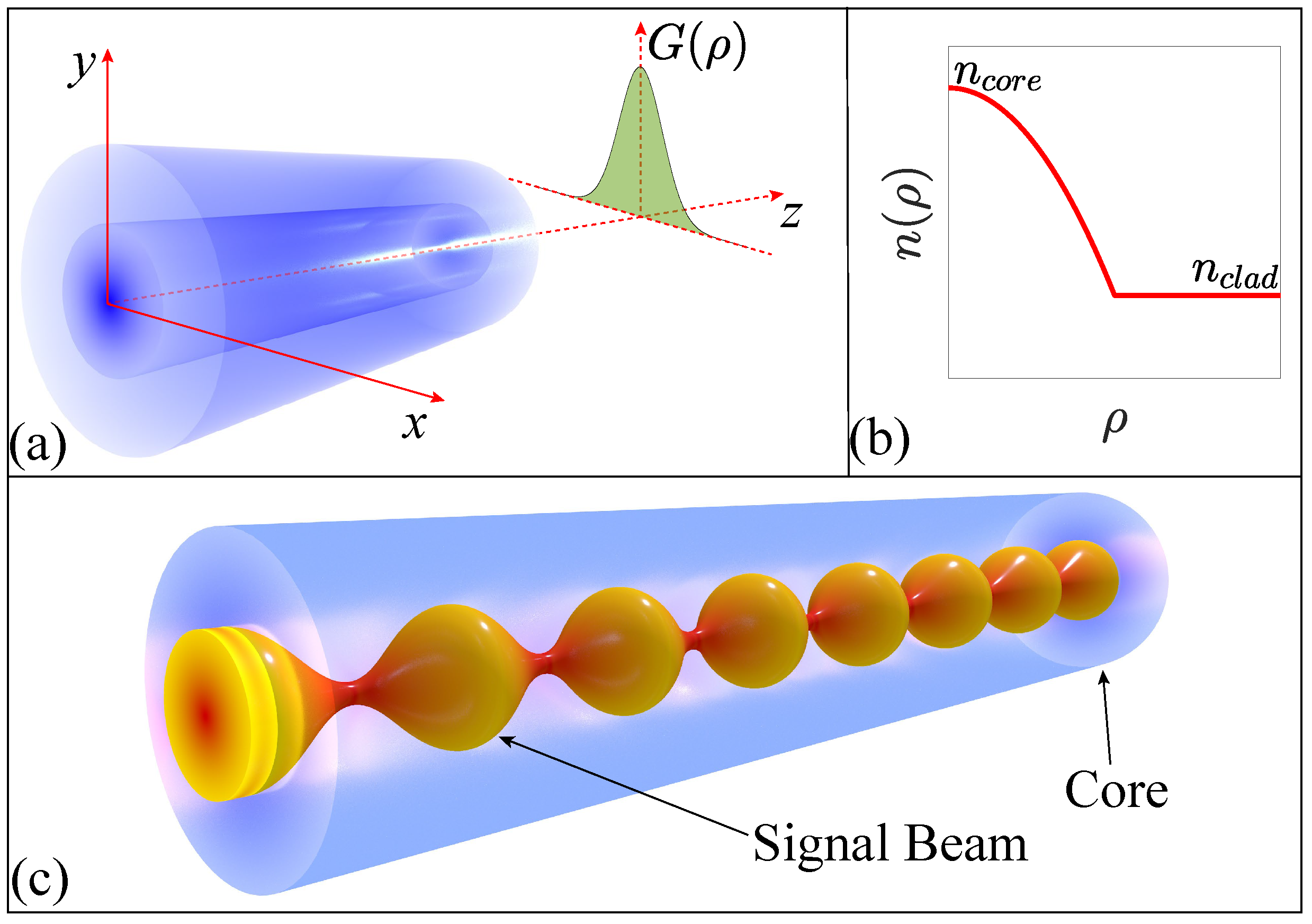
We considered a GRIN fiber with a parabolic refractive index profile and a uniform density of dopants along the radial direction. When such a fiber is pumped with a high-power laser, the gain can still vary radially and axially because of a nonuniform inversion of the dopants, as shown schematically in Figure 1. Two pumping schemes were used in practice. In the side-pumping scheme, a wide pump beam was launched into a double-clad fiber, resulting in a nearly uniform gain all along the fiber. In the case of edge pumping, a narrower pump beam was launched at the front end of the amplifier, resulting in a local gain G ( ρ , z ) that varied both radially and axially all along the fiber’s length.

2.1. Propagation Equation for the Signal Beam

In this work, we considered both pumping schemes by including the local gain G ( ρ , z ) through the imaginary part of the refractive index. The real part of the refractive index included the parabolic radial variations, together with the Kerr nonlinearity. The resulting expression for the refractive index becomes
n ( ρ , z ) = n core 1 1 2 b 2 ρ 2 + n 2 | E s | 2 i G ( ρ , z ) 2 n c o r e k 0 ,
where ρ = x 2 + y 2 is the radial distance from the center of the GRIN fiber and n core is the refractive index at ρ = 0 (see Figure 1b). The index gradient b is defined as b = 2 Δ / a , where a is the core’s radius, typically 50 μm, and Δ is the relative core–cladding index difference defined as Δ = 1 n clad / n core = 0.01. For these values, b = 2.8 × 10 3 m−1. The Kerr coefficient n 2 has a value of 2.7 × 10 20 m2/W for silica fibers. The gain G ( ρ , z ) depends on the local density of dopants and in general varies with both ρ and z. The signal to be amplified is taken in the form of a quasi-continuous beam with a narrow spectrum centered at ω 0 . The wave number k 0 in Equation (1) is defined at this frequency as k 0 = ω 0 / c , where c represents the speed of light in a vacuum.
The electric field associated with the signal beam satisfies the Helmholtz equation:
2 E s + n 2 ( ρ , z ) k 0 2 E s = 0 .
We write E s in the form E s = p ^ A s ( ρ , z ) e i k s z , where p ^ is the polarization unit vector, k s = n core k 0 , and A s ( ρ , z ) is the slowly varying amplitude of the signal. A paraxial approximation then leads to the following equation for the slowly varying amplitude:
i A s z + 2 A s 2 k s 1 2 k s b 2 ρ 2 A s + n 2 k 0 | A s | 2 A s = i 2 [ G ( ρ , z ) α l ] A s ,
where 2 is the transverse part of the Laplacian operator and α l accounts for the linear loss inside the GRIN fiber. In this equation, the effects of diffraction, index gradient, and self-phase modulation (SPM) are included through the second, third, and fourth terms, respectively.
Before solving Equation (3), a suitable form of the gain function G ( ρ , z ) is needed. In general, G ( ρ , z ) is found by solving a set of dopant-related rate equations for a pump beam, whose absorption leads to population inversion [15,20,23]. Although such an approach may be necessary for fitting the experimental data, our objective here is to develop a semi-analytical model of the beam’s amplification that contains all essential physics with reasonable accuracy. We expect the gain to follow the radial shape of the pump beam, which we assume to be Gaussian, and write the gain function G ( ρ , z ) in the form
G ( ρ , z ) = G 0 ( z ) exp ρ 2 ρ g 2 ,
where the peak gain G 0 ( z ) can vary with distance and the parameter ρ g is related to the pump beam’s spot size.

2.2. Stability of Noisy Gaussian Beams

In the absence of gain and linear loss, the solution to Equation (3) can be written in the following form [24]:
A s ( ρ , z ) = I s 0 / f s exp ρ 2 / 2 w s 0 2 f s + i θ s ( ρ , z ) ,
where I s 0 is the input peak intensity of the signal beam, with f s and C s defined as
f s ( z ) = cos 2 ( b z ) + C s 2 sin 2 ( b z ) , C s = 1 h / ( b k s w s 0 2 ) .
Here, h = P s 0 / P c , where P s 0 is the input power and P c = 2 π n c o r e / ( n 2 k s 2 ) is the critical power at which the beam collapse occurs owing to self-focusing. Notice that the beam evolves periodically (with a period z p = π / b ).
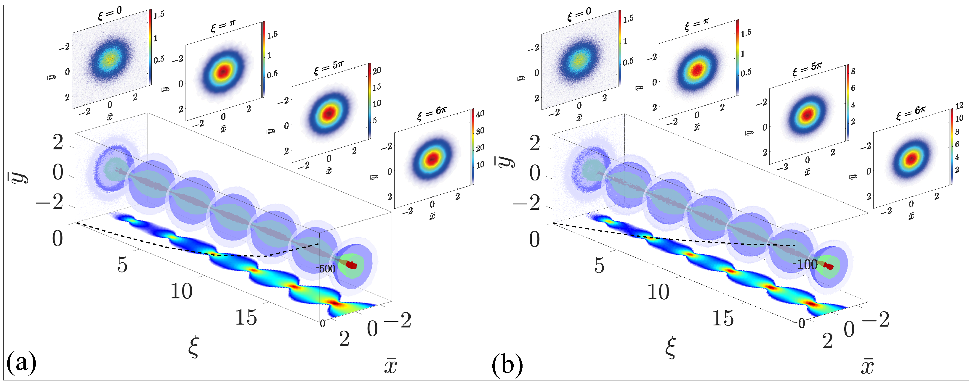
In the case of a fiber amplifier, the beam continues to evolve periodically but its amplitude increases with distance. Such an amplifying beam may face significant distortions that affect its stability. Hence, it is important to investigate the stability of the signal beam as it is being amplified. For this purpose, we propagate the signal beam by solving Equation (3) numerically, after adding distributed random noise, the peak value of which can be as much as 20% of the peak amplitude of the input signal. Figure 2 shows the evolution of such a noisy Gaussian beam inside a GRIN fiber amplifier over six self-imaging periods ( ξ = b z ) for the two pumping schemes, (a) side pumping and (b) edge pumping. The beam’s spatial profile is shown in the upper panel at four distances using the contour plots in the x y plane.
Several features are noteworthy in Figure 2. First, a noisy signal beam remained stable for both pumping schemes as it was amplified inside a GRIN fiber, while undergoing periodic self-imaging. In both cases, speckle noise added at the input end ( ξ = 0 ) was reduced significantly, ensuring the stability of the signal beam under amplification. Also, note that the beam was amplified more (dotted line showing the peak amplitude) in the case of side pumping compared to edge pumping. The reason is that the gain was nearly constant over the length of the GRIN fiber in the former case but decreased with distance in the latter case. This feature suggests that SPM-mediated self-focusing may lead to the beam’s collapse in the side-pumping case when the doped fiber is relatively long.

3. Analytical Approach

Using the explicit form of the gain profile in Equation (4), we can numerically solve Equation (3) to simulate the amplification of the signal beam. However, numerical simulations are found to be quite time-consuming for fibers longer than a few meters. A numerical approach also hinders physical insight and does not reveal which parameters are most relevant for the narrowing of the signal beam to occur. For these reasons, we adopted the variational method [25] for solving Equation (3). Such an analytic approach has been used successfully, despite the gain and loss terms that make the underlying system non-conservative [26]. The success of the variational method depends on the choice of a suitable ansatz for the beam’s shape. The method relies on the assumption that the functional form of the beam’s shape remains intact in the presence of small perturbations, even though its parameters that appear in the ansatz (amplitude, width, phase-front curvature, etc.) evolve with propagation.
As a first step, we can normalize Equation (3) using ξ = b z , r = ρ / w s 0 , and ψ s = A s / I s 0 and rewrite it as
i ψ s ξ + δ 2 2 ψ s r 2 + 1 r ψ s r 1 2 δ r 2 ψ s + γ | ψ s | 2 ψ s = i 2 [ g ( r , ξ ) α s ] ψ s .
Here, w s 0 and I s 0 are the spot size and peak intensity of the input beam; we can introduce two dimensionless parameters as
δ = ( w g / w s 0 ) 2 , γ = ω s n 2 I s 0 / ( c b ) ,
where w g = 1 / b k s is the width of the fundamental mode of the GRIN fiber. As w g is close to 5 μ m for most GRIN fibers, one expects δ < 1 in practice. The gain and loss coefficients are normalized as g ( r , ξ ) = G ( ρ , z ) / b and α s = α l / b .
To implement the variational method, we can treat the terms on the right side of Equation (7) as a small perturbation,
ϵ = 1 2 g ( r , ξ ) α s ψ s ,
and use g ( r , ξ ) = g 0 ( ξ ) exp ( r 2 / r g 2 ) with r g = ρ g / w s 0 . In the case of edge pumping, the peak gain g 0 ( ξ ) at the core’s center is expected to decrease exponentially because of the pump’s absorption, i.e., g 0 ( ξ ) = g a exp ( α g ξ ) , where g a is the peak gain at the input end of the GRIN fiber and α g is the absorption coefficient of the pump beam. In the case of side pumping, we assume that the fiber’s core is pumped uniformly from the cladding side, and set α g = 0 .
The Lagrangian density L d corresponding to Equation (7) has the form [27]
L d = i 2 r ψ s ξ ψ s * ψ s * ξ ψ s + δ 2 r | r ψ s | 2 γ 2 r | ψ s | 4 + r 3 2 δ | ψ s | 2 + i r ϵ ψ s * ϵ * ψ s ,
where ξ / ξ and r / r . We chose a Gaussian form for ψ s because the signal is often in the form of a Gaussian beam. It is important to include the curvature of the wavefront and use the form
ψ s ( r , ξ ) = ψ s 0 ( ξ ) exp r 2 2 r s 2 ( ξ ) + i d s ( ξ ) r 2 + i ϕ s ( ξ ) ,
where the four parameters ψ s 0 , r s , d s , and ϕ s correspond to the beam’s amplitude, width, wavefront curvature, and phase, respectively. All of them are allowed to vary with ξ .
Using the preceding ansatz and following the standard Rayleigh–Ritz optimization procedure [27], we obtained the reduced Lagrangian, L = 0 L d d r , by integrating over r. The result was found to be
L = 1 2 ψ s 0 2 r s 2 d ϕ s d ξ + 2 δ d s 2 + 1 2 δ + d d s d ξ ψ s 0 2 r s 4 2 + δ 4 ψ s 0 2 γ 8 ψ s 0 4 r s 2 + i 0 r ϵ ψ s * ϵ * ψ s d r .
Next, we employed the Euler–Lagrange equation, ξ ( u ξ L ) = u L , where u is one of the beam’s parameters ( ψ s 0 , r s , d s , ϕ s ) and u ξ = u / ξ . Using this equation, we obtained the following four coupled equations governing the evolution of the beam’s four parameters along the amplifier’s length:
d ψ s 0 d ξ = 2 δ d s ψ s 0 1 2 α s ψ s 0 + g 0 ( ξ ) 2 ( 1 + 2 σ 2 ) ( 1 + σ 2 ) 2 ψ s 0 ,
d r s d ξ = 2 δ d s r s g 0 ( ξ ) 2 σ 2 ( 1 + σ 2 ) 2 r s ,
d d s d ξ = 2 δ d s 2 1 2 δ + δ 2 r s 4 γ 4 ψ s 0 r s 2 ,
d ϕ s d ξ = δ r s 2 + 3 4 γ ψ s 0 2 ,
where σ = r s / r g . We used them to obtain an equation for the beam’s power P s = π ψ s 0 2 r s 2 . From the definition of P s , we obtain the relation ξ P s = 2 π ψ s 0 r s r s ξ ψ s 0 + ψ s 0 ξ r s . Now, using Equation (13a,b), we can write
d P s d ξ = α s P s + g 0 ( ξ ) ( 1 + σ 2 ) P s .
The preceding set of ordinary differential equations (ODEs) provides a stable fixed point such that r s = δ in the absence of gain, loss, and SPM. The fixed point corresponds to an input Gaussian beam whose width is matched to the fundamental mode of the GRIN fiber. In this situation, a single mode of the GRIN fiber is excited, and the beam evolves without any change in its width. When the input beam is wider and SPM is included, the beam’s width follows an oscillatory pattern [24]. When the gain is also included, the beam is amplified but its width still evolves in a periodic fashion. In this case, the preceding set of ODEs can be solved numerically much faster than Equation (7). In some situations, the accuracy of the resulting solution needs to be checked by solving Equation (7) directly.
It is possible to obtain a single differential equation for the beam’s width ( r s ) in some specific cases. For this purpose, we took the derivative of Equation (13b) and used Equation (13b,c) to eliminate d s from the resulting equation. In the absence of SPM ( γ = 0 ), r s was found to satisfy the following equation:
d 2 r s d ξ 2 = r s + δ 2 r s 3 2 ( 1 + σ 2 ) d r s d ξ α g 2 r s g 0 ( ξ ) F ( σ ) ,
where F ( σ ) = σ 2 / ( 1 + σ 2 ) 2 . In obtaining this equation, we neglected a higher-order term associated with g a because of its negligible contribution. Equation (15) offers considerable physical insight as it shows how different physical processes affect the beam’s amplification inside a GRIN fiber amplifier.
It is useful to consider the case of a passive GRIN fiber without any gain ( g 0 = 0 ). In this case, Equation (15) can be solved analytically and has the following solution [24]:
r s ( ξ ) = [ cos 2 ( ξ ) + δ 2 sin 2 ( ξ ) ] 1 / 2 .
This shows that r s varies periodically with ξ such that the signal beam recovers its initial shape at distances z = m z p , where m is an integer and z p = π / b is the self-imaging period of the GRIN fiber with a typical value of 0.6 mm. Figure 1c shows schematically the periodic evolution of such a beam inside the core of a GRIN fiber. For a fiber amplifier with finite values of g 0 , the last term in Equation (15) perturbs the solution in such a way that the width keeps oscillating with the same periodicity but does not return to its input value after each period. Depending on the amplifier design, the width may become smaller at the amplifier’s output end. As discussed later, such beam narrowing results in an improvement to the beam’s quality.

4. Results and Discussion

In this section, we solve Equation (13a–d) with the fourth-order Runge–Kutta method and study the evolution of the four parameters under different pumping conditions. In parallel, we check the accuracy of the variational solution by solving Equation (7) numerically with the standard split-step Fourier method using 2 10 Fourier points and a ξ -step of 10 3 . In both cases, we employ the same values of the parameters given in Table 1. The γ and δ values are for a realistic GRIN fiber with a = 50   μ m and Δ = 0.01 . The peak gain g a at the input end depends on the pumping level. We chose a relatively high value to ensure significant amplification over relatively short fiber lengths ( G a = 0.28 mm−1 for g a = 0.1 ). The initial values used for solving Equation (13a–d) were ψ s 0 = 1 , r s = 1 , d s = 0 , and ϕ s = 0 . We consider both the side and edge pumping cases shown schematically in Figure 3.

4.1. Case I: Side Pumping from Cladding

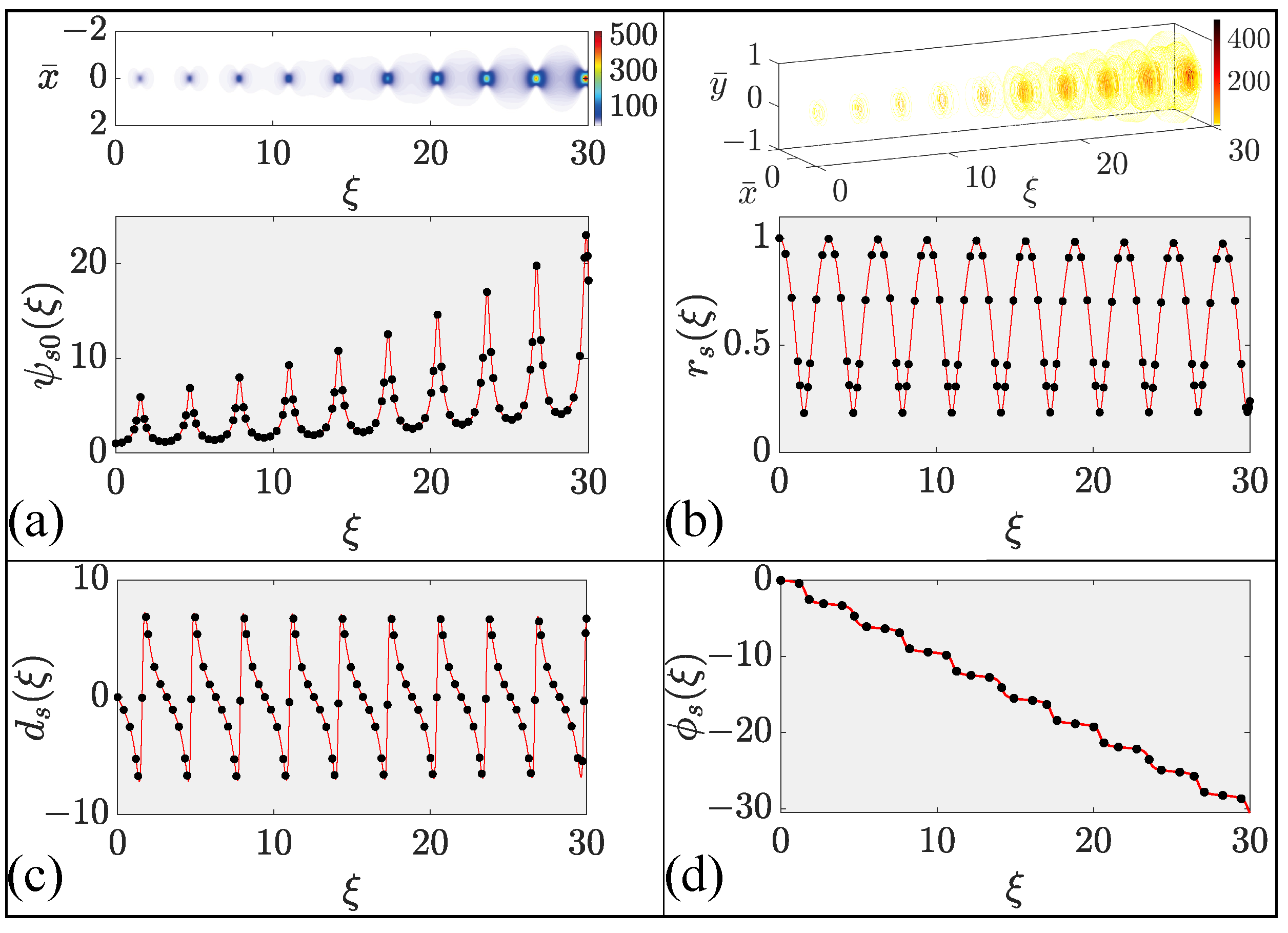
First, we consider the case of a double-clad GRIN fiber that is side-pumped using a relatively wide pump beam (see Figure 3a). We used ρ g = 75 μ m, which corresponds to a full width of 125 μ m for the input pump beam. In this pumping scheme, the gain does not change much along the fiber’s length and we used g 0 ( z ) = g a . The variational results for the beam’s amplitude, width, phase-front curvature, and phase are shown in Figure 4 as solid lines and compared with full numerical results (solid dots) over a distance that corresponds to nine self-imaging periods. An excellent agreement between the numerical and variational results seen in Figure 4 indicates that our variational analysis was able to capture all essential features of the signal beam being amplified inside a GRIN fiber amplifier.
Several features are noteworthy in Figure 4. First, as expected, all parameters of the signal beam (except its phase) oscillated because of self-imaging occurring in any GRIN fibers. As expected, the beam’s amplitude increased considerably after each period because of the pumping-induced gain provided by the dopants. However, the beam’s width almost recovered its initial value after each period, indicating no narrowing over the short length (<1 cm) used for these simulations. Although the phase-front curvature oscillated in a periodic fashion, the phase itself decreased in a monotonic fashion.

4.2. Case II: Edge Pumping from One End of the Fiber

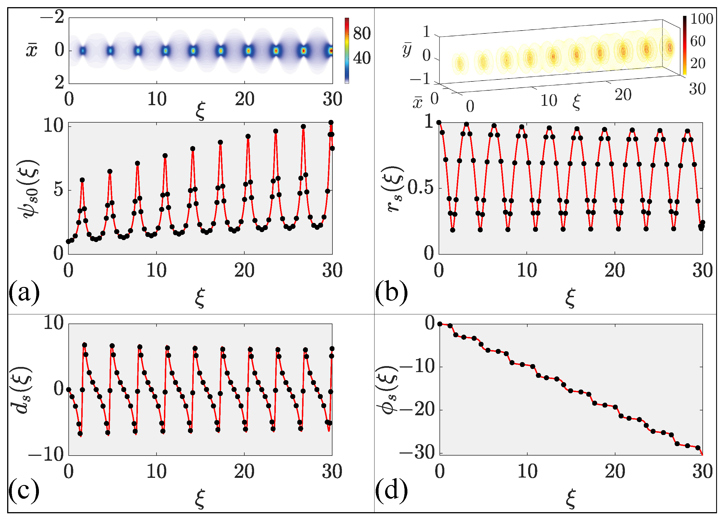
Next, we consider the case of edge pumping of a single-clad GRIN fiber that is edge-pumped using a narrower pump beam (see Figure 3b). We used ρ g = 30 μ m, which corresponds to a full width of 50 μ m for the input pump beam. The new feature, in this case, is that the peak gain decreases with distance as g 0 ( ξ ) = g a exp ( α g ξ ) owing to the absorption of pump power inside the GRIN fiber. As in Figure 4, variational results for the beam’s amplitude, width, phase-front curvature, and phase are shown in Figure 5 as solid lines and compared with full numerical results (solid dots) over a distance that corresponds to nine self-imaging periods.
A comparison of Figure 4 and Figure 5 shows that the signal beam evolves in a qualitatively similar fashion for both pumping schemes, as it is amplified inside the GRIN fiber amplifier. However, some important quantitative differences can also be seen in the two figures. One can note in part (a) that the peak amplitude is smaller by more than a factor of two near ξ = 30 in the case of edge pumping because the gain in this case decreases with distance because of the pump’s absorption. An interesting feature in part (b) is that the beam’s width does not recover its initial value after each self-imaging period, becoming smaller as the beam is amplified more and more. Smaller width values indicate that the amplified beam becomes narrower even after the relatively short distance used for Figure 5. Much more narrowing is expected to occur for longer distances. This feature suggests that edge pumping is useful for improving the quality of the amplified beam.

4.3. Average Behavior

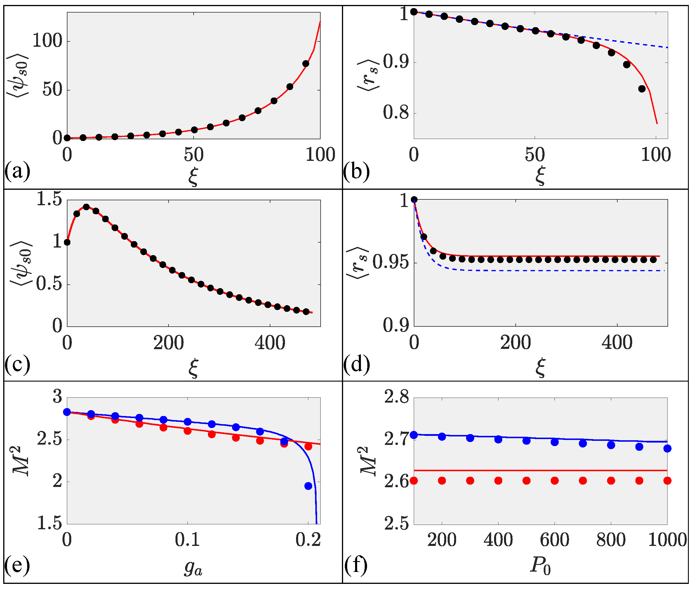
Rapid self-imaging oscillations that occur in all GRIN fibers make it harder to draw conclusions about the beam’s evolution in real amplifiers whose lengths are long enough that thousands of oscillations can occur. For this reason, we averaged the two most relevant parameters (amplitude and width) of the signal beam over such rapid oscillations. The average values were calculated by numerically integrating the beam’s amplitude and width over five self-imaging periods. The averaged values, ψ s 0 and r s , are shown in parts (a) and (b) for the clad pumping case and in parts (c) and (d) for the edge pumping case. Clearly, the two cases behaved quite differently when the fiber’s length is close to 1 m. In all cases, variational results (solid lines) agreed well with full numerical simulations (solid dots).
In the case of clad pumping, the amplitude ψ s 0 increases monotonically. At the same time, beam narrowing occurred owing to Kerr-induced self-focusing. Indeed, the beam’s collapse seemed to occur after 100 periods as the signal beam’s power approached the critical level needed for catastrophic self-focusing. This behavior is somewhat artificial because we used relatively large values of the gain, while ignoring its saturation. Nevertheless, one must be aware of the possibility of a beam’s collapse in high-power GRIN-fiber amplifiers.
In the case of edge pumping, the amplitude ψ s 0 increased initially but began to decrease after some distance (see Figure 6c). This decrease is due to exponential reduction in the gain with distance occurring because of the pump’s absorption by the dopants. At some point, the dopant-provided gain became smaller than the fiber’s loss, and the signal’s power began to decrease. For the same reason, although the average beam width r s initially decreased, it saturated at longer distances, as seen in part (d). The initial decrease was not due to self-focusing but resulted from a smaller gain in an edge-pumped amplifier away from the core’s center. The solution to Equation (15) is also shown by a dashed line in parts (b) and (d). It agrees with the variational and numerical results, except at large distances in part (b). This is expected because Equation (15) does not include the effect of SPM.
In most experiments, the quality of the output beam is judged by measuring its so-called M 2 factor. For this reason, we calculated the M 2 factor (related to the full width of the beam’s intensity at the 1 / e 2 point) as a function of gain and input signal power by exploiting our variational results. In Figure 6e, we show how the quality factor improves with increasing gain for the two pumping schemes. In the case of clad pumping (blue curve), a rapid decrease in M 2 for high gain is due to the nonlinear collapse of the beam, which is unlikely to occur in practice. Figure 6f shows how M 2 varies with the input signal power for g a = 0.1. In the case of edge pumping, the beam’s quality improves at higher input powers, but this effect does not occur for clad pumping. These trends are consistent with recent experiments [14].

4.4. Simulations for a Realistic High-Power Amplifier

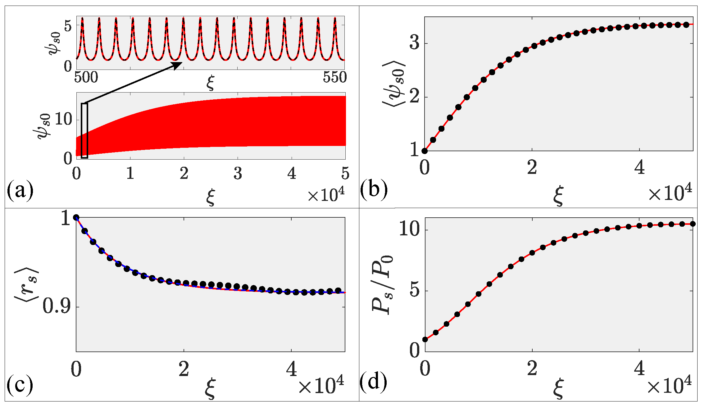
For our last example, we considered an edge-pumped GRIN fiber amplifier with realistic normalized parameters: g 0 = 2.82 × 10 4 , α g = 1.06 × 10 4 , and α s = 3.5 × 10 7 . As the amplifier’s length exceeded 10 m in practice, we ran our simulations over a distance of about 20 m. Figure 7 shows the evolution of (a) the amplitude ψ s 0 , (b) its average over five self-imaging cycles, (c) the average width r s , and (d) the amplification factor P s / P 0 . As expected, ψ s 0 evolves periodically with increasing amplitude owing to the beam’s amplification. The inset in part (a) shows periodic self-imaging on a magnified scale. The averages amplitude of the beam in part (b) increases first but saturates after some distance because of the pump’s absorption along the fiber’s length. Part (c) shows that the beam’s width is reduced first by about 10%, but it saturates when amplification becomes negligible at long distances. The dashed line in part (c) shows the solution of Equation (15) for comparison. In plot (d), the signal’s power P s in parts (d) increases with distance, initially owing to amplification, but saturates eventually because of the loss of pump power at large distances. The net gain at the end of the fiber is about 10 dB for the parameters used in this simulation. In all cases, the variational results (solid line) agree well with full numerical simulations (solid dots). It is important to stress that full numerical simulations took more than a day to complete, while variational calculations were over in a few minutes using the same computer.
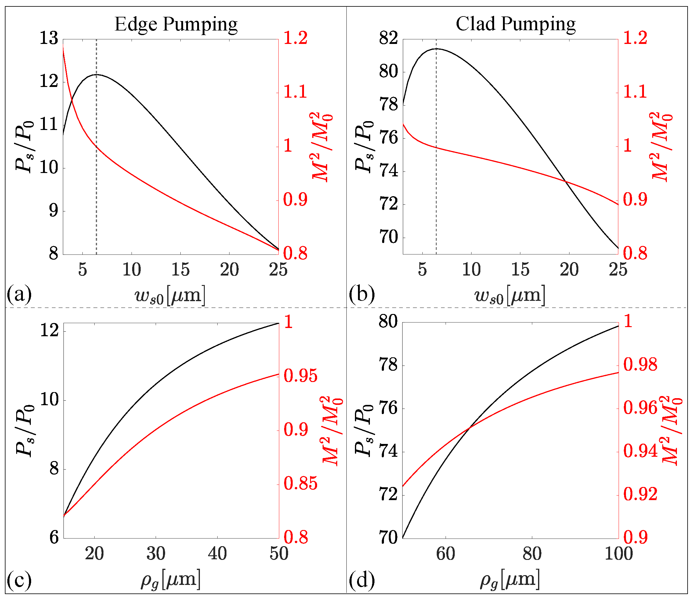
With the verification of the accuracy of variational results, we can employ our analysis for a parametric study of amplifier characteristics. Figure 8 illustrates how the relative signal power ( P s / P 0 ) and beam quality ( M 2 / M 0 2 ) vary for edge (left column) and clad (right column) pumping schemes at the output of the GRIN amplifier as a function of w s 0 (top row) and ρ g (bottom row). To avoid SPM-induced collapse for the constant gain clad pumping system, the fiber length is limited to 5 m.
Interestingly, for both pumping schemes, the signal’s output power reached the maximum when w s 0 = w g (≈6 μ m), marked with a vertical dashed line in Figure 8. Also, the amplification of the signal improved with increasing radial gain width ( ρ g ), but the beam’s quality degraded for both the pump schemes. Similar to Figure 6, the edge pumping scheme showed an improvement in beam quality, while clad pumping provided more amplification. Further, in both the cases [see parts (c) and (d)], an increase in the radial gain width resulted in higher amplification but deterioration in the beam quality. These results should be useful for optimizing the device design. Parameter values used for the realistic numerical simulations in Figure 7 and Figure 8 are provided as a Table A1 in Appendix A.

5. Conclusions

Graded-index fibers have been used in recent years for making high-power fiber lasers and amplifiers. Such undoped fibers exhibit periodic focusing and self-imaging that restore any optical beam to its original shape after distances shorter than 1 mm. In this work, we employed analytical and numerical techniques to study how the self-imaging phenomenon affects the evolution of a signal beam inside a nonlinear graded-index fiber amplifier, doped with a rare-earth element and pumped optically to provide gain all along its length.
We developed a fully numerical model based on a multidimensional nonlinear Schrödinger equation that includes both the nonlinear Kerr effect and the optical gain provided by the dopants. We also exploited the variational technique to reduce the computing time and to provide physical insights into the amplification process. This provided a simple set of ordinary differential equations describing the evolution of four parameters associated with a Gaussian input beam. We compared the variational and fully numerical results for the two pumping schemes (clad pumping and edge pumping) commonly used for high-power fiber amplifiers and showed that the variational results are reliable in most cases of practical interest.
The stability of the signal beam undergoing amplification was examined numerically by launching a noisy Gaussian beam at the input end of the amplifier. It was found that a noisy beam not only remained stable but that its noise was even reduced with the beam’s amplification. We discussed in considerable detail how the parameters of a signal beam changed along the fiber’s length as the beam was amplified inside a GRIN fiber after including most relevant effects such as diffraction, self-imaging, and nonlinear self-focusing. We included the radial and axial variations of the pumping-induced optical gain using a simple model that neglected gain saturation. Our results show that the quality of the amplified beam should improve in the case of edge pumping when a narrower pump beam provides an optical gain that varies considerably in the radial direction of the fiber. Such an improvement did not occur for the clad pumping scheme, for which the use of a relatively wide pump beam resulted in a nearly uniform gain all along the fiber. Our investigation provided considerable physical insight into the amplification process inside an active GRIN fiber and revealed which parameters should be controlled to realize the narrowing of the amplified beam, a feature that improved the beam’s quality at the amplifier’s output.
Author Contributions

Conceptualization, G.P.A.; Software, A.P.L.; Formal analysis, S.R.; writing—original draft preparation, A.P.L.; writing—review and editing, G.P.A. All authors have read and agreed to the published version of the manuscript.

Funding

A.P.L acknowledges University Grants Commission, India, for support through the Senior Research Fellowship in Sciences, Humanities and Social Sciences (Grant No. 515364).

Institutional Review Board Statement

Not applicable.

Informed Consent Statement

Not applicable.

Data Availability Statement

Data are contained within the article.

Conflicts of Interest

The authors declare no conflicts of interest.

Appendix A

Table A1. List of parameters used for the realistic numerical analysis presented in Figure 7 and Figure 8.
ParameterSymbolValue [Units]
Core radiusa50 [ μ m]
Relative index difference Δ 0.01
Refractive index gradientb 2.8 × 10 3 [m−1]
Kerr coefficient n 2 2.7 × 10 20 [m2 W]
Operating wavelength λ 0 1060 [nm]
Fundamental mode width w g 6.4 [ μ m]
Input signal beam width w s 0 15 [ μ m]
Radial gain width ρ g 30 [ μ m] (edge pumping)
75 [ μ m] (clad pumping)
Peak gain coefficient G 0 0.8 [m−1]
Gain decay coefficient α g 0.3 [m−1]
Linear loss coefficient α s 1 × 10 3 [m−1]
Signal input power P 0 100 [W]

References

  1. Uchida, T.; Furukawa, M.; Kitano, I.; Koizumi, K.; Matsumura, H. Optical characteristics of a light-focusing fiber guide and its applications. IEEE J. Quantum Electron. 1970, 6, 606–612. [Google Scholar] [CrossRef]
  2. Richardson, D.J.; Fini, J.M.; Nelson, L.E. Space-division multiplexing in optical fibres. Nat. Photonics 2013, 7, 354–362. [Google Scholar] [CrossRef]
  3. Renninger, W.H.; Wise, F.W. Optical solitons in graded-index multimode fibres. Nat. Commun. 2013, 4, 1719. [Google Scholar] [CrossRef]
  4. Wright, L.G.; Wabnitz, S.; Christodoulides, D.N.; Wise, F.W. Ultrabroadband Dispersive Radiation by Spatiotemporal Oscillation of Multimode Waves. Phys. Rev. Lett. 2015, 115, 223902. [Google Scholar] [CrossRef]
  5. Wright, L.G.; Christodoulides, D.N.; Wise, F.W. Controllable spatiotemporal nonlinear effects in multimode fibres. Nat. Photonics 2015, 9, 306–310. [Google Scholar] [CrossRef]
  6. Wright, L.G.; Liu, Z.; Nolan, D.A.; Li, M.J.; Christodoulides, D.N.; Wise, F.W. Self-organized instability in graded-index multimode fibres. Nat. Photonics 2016, 10, 771–776. [Google Scholar] [CrossRef]
  7. Wright, L.G.; Christodoulides, D.N.; Wise, F.W. Spatiotemporal mode-locking in multimode fiber lasers. Science 2017, 358, 94–97. [Google Scholar] [CrossRef] [PubMed]
  8. Qin, H.; Xiao, X.; Wang, P.; Yang, C. Observation of soliton molecules in a spatiotemporal mode-locked multimode fiber laser. Opt. Lett. 2018, 43, 1982. [Google Scholar] [CrossRef]
  9. Lopez-Galmiche, G.; Sanjabi Eznaveh, Z.; Eftekhar, M.A.; Antonio Lopez, J.; Wright, L.G.; Wise, F.; Christodoulides, D.; Amezcua Correa, R. Visible supercontinuum generation in a graded index multimode fiber pumped at 1064 nm. Opt. Lett. 2016, 41, 2553. [Google Scholar] [CrossRef]
  10. Eslami, Z.; Salmela, L.; Filipkowski, A.; Pysz, D.; Klimczak, M.; Buczynski, R.; Dudley, J.M.; Genty, G. Two octave supercontinuum generation in a non-silica graded-index multimode fiber. Nat. Commun. 2022, 13, 2126. [Google Scholar] [CrossRef]
  11. Krupa, K.; Louot, C.; Couderc, V.; Fabert, M.; Guenard, R.; Shalaby, B.M.; Tonello, A.; Pagnoux, D.; Leproux, P.; Bendahmane, A.; et al. Spatiotemporal characterization of supercontinuum extending from the visible to the mid-infrared in a multimode graded-index optical fiber. Opt. Lett. 2016, 41, 5785. [Google Scholar] [CrossRef] [PubMed]
  12. Krupa, K.; Tonello, A.; Barthélémy, A.; Couderc, V.; Shalaby, B.M.; Bendahmane, A.; Millot, G.; Wabnitz, S. Observation of Geometric Parametric Instability Induced by the Periodic Spatial Self-Imaging of Multimode Waves. Phys. Rev. Lett. 2016, 116, 183901. [Google Scholar] [CrossRef] [PubMed]
  13. Krupa, K.; Tonello, A.; Shalaby, B.M.; Fabert, M.; Barthélémy, A.; Millot, G.; Wabnitz, S.; Couderc, V. Spatial beam self-cleaning in multimode fibres. Nat. Photonics 2017, 11, 237–241. [Google Scholar] [CrossRef]
  14. Guenard, R.; Krupa, K.; Dupiol, R.; Fabert, M.; Bendahmane, A.; Kermene, V.; Desfarges-Berthelemot, A.; Auguste, J.L.; Tonello, A.; Barthélémy, A.; et al. Kerr self-cleaning of pulsed beam in an ytterbium doped multimode fiber. Opt. Express 2017, 25, 4783. [Google Scholar] [CrossRef] [PubMed]
  15. Jima, M.A.; Tonello, A.; Niang, A.; Mansuryan, T.; Krupa, K.; Modotto, D.; Cucinotta, A.; Couderc, V.; Wabnitz, S. Numerical analysis of beam self-cleaning in multimode fiber amplifiers. J. Opt. Soc. Am. B 2022, 39, 2172. [Google Scholar] [CrossRef]
  16. Mangini, F.; Gervaziev, M.; Ferraro, M.; Kharenko, D.S.; Zitelli, M.; Sun, Y.; Couderc, V.; Podivilov, E.V.; Babin, S.A.; Wabnitz, S. Statistical mechanics of beam self-cleaning in GRIN multimode optical fibers. Opt. Express 2022, 30, 10850. [Google Scholar] [CrossRef]
  17. Haig, H.; Bender, N.; Chen, Y.H.; Dhar, A.; Choudhury, N.; Sen, R.; Christodoulides, D.N.; Wise, F. Gain-induced Kerr beam cleaning in a femtosecond fiber amplifier. J. Opt. Soc. Am. B 2023, 40, 1510. [Google Scholar] [CrossRef]
  18. Mangini, F.; Ferraro, M.; Sun, Y.; Gervaziev, M.; Parra-Rivas, P.; Kharenko, D.S.; Couderc, V.; Wabnitz, S. Modal phase-locking in multimode nonlinear optical fibers. Opt. Lett. 2023, 48, 3677. [Google Scholar] [CrossRef] [PubMed]
  19. Sidelnikov, O.S.; Podivilov, E.V.; Fedoruk, M.P.; Kuznetsov, A.G.; Wabnitz, S.; Babin, S.A. Mechanism of brightness enhancement in multimode LD-pumped graded-index fiber Raman lasers: Numerical modeling. Opt. Express 2022, 30, 8212. [Google Scholar] [CrossRef]
  20. Chen, Y.H.; Haig, H.; Wu, Y.; Ziegler, Z.; Wise, F. Accurate modeling of ultrafast nonlinear pulse propagation in multimode gain fiber. J. Opt. Soc. Am. B 2023, 40, 2633. [Google Scholar] [CrossRef]
  21. Agrawal, G.P. Spatial beam narrowing in multimode graded-index fiber amplifiers: An analytic approach. Opt. Lett. 2023, 48, 259–262. [Google Scholar] [CrossRef] [PubMed]
  22. Paul, A.; Lara, A.P.; Roy, S.; Agrawal, G.P. Spatial beam dynamics in graded-index multimode fibers under Raman amplification: A variational approach. Phys. Rev. A 2023, 108, 063507. [Google Scholar] [CrossRef]
  23. Saleh, A.; Jopson, R.; Evankow, J.; Aspell, J. Modeling of gain in erbium-doped fiber amplifiers. IEEE Photonics Technol. Lett. 1990, 2, 714–717. [Google Scholar] [CrossRef]
  24. Karlsson, M.; Anderson, D.; Desaix, M. Dynamics of self-focusing and self-phase modulation in a parabolic index optical fiber. Opt. Lett. 1992, 17, 22–24. [Google Scholar] [CrossRef] [PubMed]
  25. Anderson, D. Variational approach to nonlinear pulse propagation in optical fibers. Phys. Rev. A 1983, 27, 3135–3145. [Google Scholar] [CrossRef]
  26. Roy, S.; Bhadra, S.K.; Agrawal, G.P. Raman amplification of optical pulses in silicon waveguides: Effects of finite gain bandwidth, pulse width, and chirp. J. Opt. Soc. Am. B 2008, 26, 17. [Google Scholar] [CrossRef]
  27. Anderson, D.; Cattani, F.; Lisak, M. On The Pereira-Stenflo Solitons. Phys. Scr. 1999, T82, 32. [Google Scholar] [CrossRef]
Figure 1. Schematic of a GRIN fiber amplifier with (a) radially varying gain and (b) a parabolic index profile. (c) Schematic showing how the signal beam evolves in a periodic fashion inside such a GRIN fiber because of self-imaging provided by the parabolic index profile.
Photonics 11 00737 g001
Figure 2. Evolution of a noisy Gaussian beam inside a GRIN fiber amplifier over a distance of 6 periods ( ξ = 6 π ): (a) side pumping and (b) edge pumping. We scaled the x and y coordinates using the beam’s input width w s 0 . The beam’s spatial profile is shown in the upper panel at four distances.
Photonics 11 00737 g002
Figure 3. Schematic of two pumping schemes: (a) side pumping and (b) edge pumping.
Photonics 11 00737 g003
Figure 4. Comparison of the variational (lines) and numerical (dots) predictions for side pumping: (a) amplitude, (b) width, (c) phase-front curvature, and (d) phase of the signal beam for α g = 0 (see Table 1 for other parameters). The top part in (a) shows periodic self-imaging of the signal beam in the y = 0 plane. The beam’s 3D evolution is shown in the top part of (b).
Photonics 11 00737 g004
Figure 5. Same as Figure 4 except that the variational (lines) and numerical (dots) results are compared in the case of edge pumping using α g = 0.05 . Other parameters are identical to those used in Figure 4 and given in Table 1.
Photonics 11 00737 g005
Figure 6. Changes with distance in the averaged (a,c) amplitude and (b,d) width of the signal beam in the case of clad pumping (top row) and edge pumping (bottom row). Variational results are shown by lines while solid dots corresponding to numerical simulations. Dashed lines in (b,d) show the solution of Equation (15). Beam’s quality factor M 2 (e) as a function of g a for P s 0 = 100 W and (f) as a function of input signal power for g a = 0.1 . The blue and red lines correspond to clad and edge pumping, respectively; solid dots are for numerical simulations.
Photonics 11 00737 g006
Figure 7. Comparison of the variational (lines) and numerical (solid dots) predictions for a 20-m-long GRIN fiber amplifier with realistic parameter values given in the text. (a) Evolution along the fiber’s length of the beam’s (a) amplitude ψ s 0 , (b) its average value, (c) average width r s , and (d) amplification factor. Inset in part (a) shows periodic self-imaging on a magnified scale.
Photonics 11 00737 g007
Figure 8. Variation of the relative signal power and beam quality ( M 2 factor) as a function of input signal width w s 0 (a,b) and radial gain width ρ g (c,d) for edge (left column) and clad (right column) pumping schemes.
Photonics 11 00737 g008
Table 1. Parameter values used in numerical simulations.
ParametersSymbolsValues
Normalized nonlinear coefficient γ 4 × 10 6
Width ratio δ 0.09
Normalized gain amplitude g a 0.1
Input signal power P s 0 100 W
Input beam’s width w s 0 15 μ m
Linear loss of GRIN fiber α l 2 × 10 3 m−1
Disclaimer/Publisher’s Note: The statements, opinions and data contained in all publications are solely those of the individual author(s) and contributor(s) and not of MDPI and/or the editor(s). MDPI and/or the editor(s) disclaim responsibility for any injury to people or property resulting from any ideas, methods, instructions or products referred to in the content.