Abstract
Modern stealth application systems require integrated meta-devices to operate effectively and have gained significant attention recently. This research paper proposes a 1-bit coding metasurface (CM) design. The fundamental component of the proposed CM is integrated to convert linearly polarized incoming electromagnetic waves into their orthogonal counterpart within frequency bands of 12.37–13.03 GHz and 18.96–32.37 GHz, achieving a polarization conversion ratio exceeding 99%. Furthermore, it enables linear-to-circular polarization conversion from 11.80 to 12.29, 13.17 to 18.44, and 33.33 to 40.35 GHz. A second element is produced by rotating a fundamental component by 90°, introducing a phase difference of π (pi) between them. Both elements are arranged in an array using a random aperiodic coding sequence to create a 1-bit CM for reducing the radar cross-section (RCS). The planar structure achieved over 10 dB RCS reduction for polarized waves in the frequency bands of 13.1–13.8 GHz and 20.4–30.9 GHz. A prototype was fabricated and tested, with the experimental results showing a good agreement with the simulated outcomes. The proposed design holds potential applications in radar systems, reflector antennas, stealth technologies, and satellite communication.
1. Introduction
Polarization converters play a crucial role in modern wireless communication due to their diverse applications, including radar cross-section (RCS) reduction [1], liquid crystal displays, and circularly polarized antennas [2]. Polarization conversion can be accomplished with the use of conventional techniques such as liquid crystals [3], birefringence wave plates [4], Faraday effects [5], etc. Many conventional techniques face limitations in real-world applications due to drawbacks such as high thickness and inadequate bandwidth. To overcome these limitations, specially constructed structures called metasurfaces (MSs) have been introduced. Metasurfaces are typically low-profile and made of lightweight materials. They offer advantages such as easy fabrication, good conversion characteristics, small size, and the ability to manipulate electromagnetic wave polarization precisely. By employing metasurfaces, the shortcomings of traditional design methods can be effectively avoided, providing a powerful tool for controlling polarization and manipulating beams. Metasurfaces have demonstrated their capability to manipulate polarization across multiple frequency regimes, including visible [6,7], terahertz [8,9], infrared [10], and microwave [11]. In recent years, various polarization conversion metasurfaces (PCMs) have been proposed to achieve different types of polarization conversions. These include incident and reflective orthogonal linear polarization (LP-LP) [12,13,14,15], circular-to-circular polarization [16,17,18,19], and linear-to-circular polarization (LP-CP) [20,21,22,23]. However, many of these metasurfaces are designed to realize only a single polarization conversion function, and there are relatively few metasurfaces capable of multiple polarization conversion functions. Hence, there is an urgent need to investigate multifunctional polarization conversion metasurfaces (PCMs) across various frequency bands. Addressing this demand, the literature [22] has proposed diverse functions for polarization converters, achieving a linear polarization conversion bandwidth of up to 95.2%. Gao et al. have developed a voltage-controlled reconfigurable broadband PCM capable of LP-LP and LP-CP conversions [23]. In [24], a four-band, multifunctional reflective polarization converter based on linear and circular polarizations was introduced. However, modern application systems call for integrated multifunctional devices. These devices not only minimize system size by replacing multiple components with a single multifunctional component but also reduce overall system complexity and cost. Consequently, research efforts have been focused on developing compact, cost-effective metasurfaces capable of both cross and circular polarization conversions [25,26,27].
One of the most efficient applications of polarization conversion metasurfaces is the reduction in the radar cross-section, which is crucial for military technologies to evade hostile radar detection. There are generally two techniques utilized to achieve lower RCS metamaterials and artificial structures. The first approach involves employing radar-absorbing materials, such as absorbers like Jaumann [28], Salisbury screens [29], magnetic absorbers [30], circuit analog absorbers [31], and frequency-selective surfaces [32,33,34,35,36], to absorb the energy of incoming waves. However, these absorbers often have limited absorption bandwidth due to their thickness and structure. Additionally, absorbing electromagnetic waves can raise the temperature and increase the likelihood of infrared light detection. Another technique to reduce the radar cross-section involves the use of diffusion metasurfaces, which scatter reflected electromagnetic waves away from their source. In this context [37], the term ‘coding metasurface’ was first introduced by Cui et al. in 2014. The design process of a CM begins with the original design of numerous opposing phase coding elements, arranged in the most optimal feasible order. One approach to generating multiple coding elements with significant phase changes is by altering the structure’s size or deploying different components. However, this approach increases design complexity and requires considerable time and effort [38]. In contrast, the Pancharatnam–Berry (PB) phase development enables the necessary phase difference to be achieved simply by rotating an anisotropic structure, without the need for a wide range of isotropic elements or changes in specific structural dimensions. Numerous studies have utilized this idea to reduce the RCS, as reported in the literature [33,34,35,36].
Based on the above discussions, we propose a simple circular ring MS design capable of achieving linear polarization conversion within the central frequency band while accomplishing linear-to-circular conversion at lower and higher frequency ranges. In pursuit of this objective, our initial step involves designing a structure endowed with wide-angle and polarization insensitivity attributes. Later, employing the PB phase, numerous meta-atoms arranged in a randomized array sequence were utilized to fabricate a 1-bit coding metasurface for reducing the radar cross-section. Numerical simulations, complemented by experimental measurements, validate that the 1-bit CM structure can attain a reduction of over 10 dB in the RCS for a single wideband at the central frequency, along with LP–CP conversion within the two sidebands’ window. Our design is ideally suited for deployment in stealth applications across various K-bands.
2. Metasurface Design
Figure 1a illustrates the proposed modified circular ring meta-atom-based unit cell designed to operate as a polarization converter. As shown in Figure 1b, the proposed unit cell is composed of two stacked layers: air and a commercially available Rogers RT5880 substrate. The unit cell is printed on top of an RT5880 substrate with = 2.2, tanδ = 0.0009, where the bottom copper layer is entirely removed. The thin layer of Rogers RT5880 is also separated from the ground copper sheet by an air gap. The bottom layer and top structure are composed of copper, with a thickness of 35 µm and an electrical conductivity of S/m. The CST Microwave Studio is a well-known commercial full-wave simulation program used for simulating unit cells. Specifically, we incorporated a Floquet port to direct electromagnetic waves onto the proposed meta-atom in the z-direction, as illustrated in Figure 1c. For the z-direction, an open boundary was implemented, while unit cell boundary conditions were applied for the x and y axes. Figure 1 depicts the geometry of the proposed unit cell, where the initial cell dimensions are considered as P = 6 mm, w = 1.2 mm, r = 2.4 mm, ri = 1.2 mm, h = 0.127 mm, and hair = 1.4 mm. To investigate the polarization conversion property, a y-polarized incident wave is allowed to impinge on the unit cell converter. Figure 1c displays the simulation setup. Due to the anisotropic nature of the structure, the reflected wave contains both co- and cross-polarized components. These components can be expressed as follows:
where and represent the reflection coefficients for co- and cross-polarization, respectively, and the electric field is denoted by E. is an electric field of reflected waves, and are the reflected fields. The reflected and incident subscripts are denoted by the symbols r and i, respectively. The linear polarization conversion performance of the converter is assessed using the following expressions for the polarization conversion ratio (PCR) and polarization conversion efficiency (PCE).
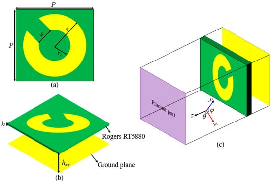
Figure 1.
The schematic diagram of the proposed unit cell: (a) top view, (b) side view of proposed meta-atom, and (c) isometric view and simulation setup.
Figure 2 displays the - and -polarized reflection responses, as well as the polarization conversion efficiency from the converter. Figure 2a demonstrates that within the dual-frequency range of 12.37–13.03 GHz and 18.96–32.37 GHz, the magnitude of cross-polarization reflection exceeds −1 dB, while the magnitude of co-polarization reflection remains below −10 dB. Figure 2b depicts the calculated polarization conversion efficiency using Equation (3).
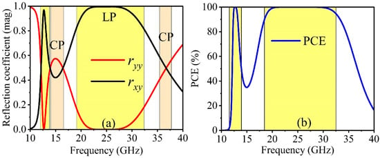
Figure 2.
The simulated result of proposed unit cell: (a) reflection coefficient in magnitude () and (b) polarization conversion efficiency (%).
It is evident that within the dual-frequency bands of 12.37–13.03 GHz and 18.96–32.37 GHz, the PCE value exceeds 95%. This substantiates the effectiveness of the proposed converter as a linear polarization converter within the mentioned frequency bands.
Another significant functionality of the proposed metasurface is its capability to convert linear to circular polarization or operate as a quarter-wave plate (QWP). In an ideal scenario, a design that offers LP-CP conversion must satisfy two conditions: The co- and cross-polarized reflected components must be approximately equal. Simultaneously, the phase difference between these two components should be or an odd multiple of , which can be expressed as , and , where n is an odd number.
Figure 3a demonstrates that linear-to-circular conversion is achievable over the frequency bands of 11.80–12.29 GHz, 13.17–18.44 GHz, and 33.33–40.35 GHz with equal amplitudes (), fulfilling the first criterion. Furthermore, as illustrated in Figure 3a, the phase difference between these two components is also close to or an odd multiple of . Thus, both criteria for LP-CP conversion have been met within the frequency range of 11.80–12.29 GHz, 13.17–18.44 GHz, and 33.33–40.35 GHz. Moreover, the conversion from linear to circular polarization is deemed valid even when the axial ratio (AR) of the co- and cross-polarized components remains below 3 dB. The AR can be expressed as follows for a normal y-polarized incident wave:
where ‘β’ can be expressed as
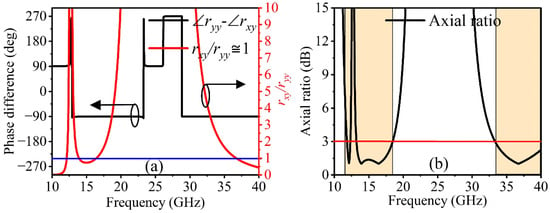
Figure 3.
(a) Calculated results of phase difference (deg) and amplitude ratio (); (b) axial ratio (AR 3 dB).
Also, for the x-polarized incident wave, subscripts y and x will be replaced in Equations (4) and (5). The operating bandwidth for circular polarization is defined as the AR curve with less than 3 dB, as shown in Figure 3b. Thus, Figure 3b illustrates that linear-to-circular conversion can be achieved within the frequency range of 11.80–12.29, 13.17–18.44, and 33.33–40.35 GHz, with a 4.06%, 33.35%, and 19.05% fractional bandwidth.
3. Angular Stability
The metasurface response is rigorously evaluated through its angular stability performance. In practically every application, the metasurfaces’ response must be independent of the electromagnetic wave’s incidence angle. Our metasurface has been evaluated and optimized for various incidence angles. Figure 4 illustrates an evaluation of a metasurface’s polarization conversion efficiency and AR under an oblique incident EM wave. The angular stability for linear polarization operation can be observed using the polarization conversion ratio, as illustrated in Figure 4a. Within two frequency ranges, the PCR shows a stable response up to an incidence angle of 40°.
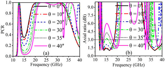
Figure 4.
Simulated results at oblique incidences: (a) PCR and (b) axial ratio (AR ≤ 3 dB).
On the other hand, as the oblique angle increases, a slight forward frequency shift is observed in both frequency bands. While the oblique incidence (35° and 40°) in the upper-frequency band only had an offset effect on the frequency bands, it had slight effects on the bandwidth of 12.37–13.03 GHz and had no impact on the circular polarization conversion at 11.80–12.29 GHz in terms of linear-to-circular polarization conversion, as shown in Figure 4b. Moreover, the AR response shows stability up to an incidence angle of 30°. Thus, under oblique incidence, the LP-CP conversion could maintain the multi-band function and remain stable in the higher frequency range.
4. Operating Principle
In order to understand the proposed metasurface functions as a linear polarizer, the E-field component beside the y-axis can be decomposed into two orthogonal u and v components, which are on ±45° concerning the x- and y-axes. The u and v components of an incident y-polarized electromagnetic wave can be divided, as shown in Figure 5a. We evaluate the incident and reflected electric field along the u- and v-axes, which are represented, respectively, by and , and and . The decomposed u and v components of the incident and reflected electric field are expressed as follows:
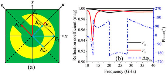
Figure 5.
(a) Proposed meta-atom with UV-coordinates, and (b) magnitude ( and ) and reflection phase difference in u- and v-polarized waves.
When u- and v-polarized incident electromagnetic waves are the incoming waves, the unit vectors in the equation above are and , and the co-polarized components are represented by and with their relative phases and , respectively. Because of its asymmetric design, the converter shows anisotropic characteristics such as dispersive relative permittivity and permeability. Thus, there can be variations in the phase between and . Figure 5b illustrates that the synthetic field along the y-direction results when and (k is an integer); will be opposite to , and remains the same as , respectively. Figure 5b shows the amplitude and phase difference in the reflection coefficients. It is noted that the reflection amplitudes ( and ) are nearly equal to unity with between 12.37–13.03 GHz and 20.10–28.30 GHz. In dual-frequency bands, it implies the proposed structure is capable of LP-LP conversion.
Nonetheless, the phase difference of is required for LP–CP conversion. Furthermore, at the frequency bands of 12.06, 13.76–16.44, and 36.75–38.80 GHz, a phase difference of nearly is realized, indicating LP–CP conversion. To provide more details about the physical process causing the polarization conversion, we evaluate the surface currents on the metasurface at resonance frequencies. At resonant frequencies, Figure 6a–c show the surface current orientations on the top copper layer and bottom ground copper layer of the proposed converter. To be more precise, magnetic resonance occurs when the current causes the top and bottom metallic plates to be in opposite directions from one another, and electric resonance occurs when the surface current distribution is parallel on the top metallic pattern and bottom ground plane. At the resonant frequency of 12.47 GHz, Figure 6a renders that the surface currents at the top layer are parallel to the ones at the bottom. In the case of 20.08 GHz and 32.56 GHz resonance frequencies, magnetic resonance occurs due to the opposite surface currents at the top layer and the ground plate, as shown in Figure 6b,c. Thus, current loops that occur in the dielectric layer provide a cause for magnetic resonance. The magnetic field produced by these antiparallel currents is amplified in the dielectric area, leading to a high magnetic permeability value. The surface impedance of the structure is significantly higher than that of air or free space because of the high magnetic permeability. Consequently, high-impedance surface behavior shows up by the surface, which is essential for cross-polarization conversion.
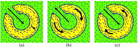
Figure 6.
Surface current distribution at different resonance frequencies: (a) 12.47 GHz, (b) 20.08 GHz, and (c) 32.56 GHz.
5. Configuration and Analysis of RCS Reduction with Coding Metasurface
The radar cross-section determines a target’s detectability to an approaching radar system. Although a low RCS hinders enemy radar from identifying combat targets like missiles, planes, and rockets, it is crucial for stealth technology because it improves their surveillance capabilities. Given the significance of a low radar cross-section, the remarkable ability of a coding metasurface to scatter the EM wave in several directions to reduce scattering energy in all directions and reduce the radar cross-section is of great interest. Different coding elements with distinct phases distributed over a constant amplitude produce a coding metasurface. With the addition of the PB phase, an anisotropic structure can easily be rotated to produce the phase difference instead of requiring several isotropic elements or adjusting its size attributes. The PB phase indicates that rotating the top metal pattern by results in a reflection phase change of . In order to obtain a phase difference for a 1-bit CM, is rotated by . Figure 7 shows the mechanism. Figure 7a depicts the layout of the meta-atoms ‘1’ and ‘0’. From Figure 7b, the phase difference of meta-atoms ‘1’ and ‘0’ is equal to ±180°. Ref. [35] states that the far-field scattering caused by a coding metasurface can be written as follows:
where and stand for the radiation intensity of each element and array factor, respectively, whereas stands for the wavenumber vector, and is the lattice size. and are the azimuth and elevation angle. We suppose that , which can be either or , represents the scattering phase of each lattice. Hence, the phase difference between “0” and “1” causes , and the directivity function of the metasurface can be written as follows:
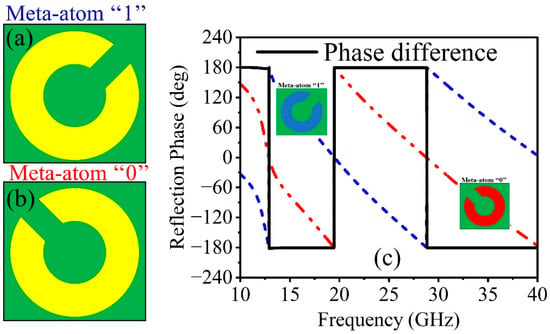
Figure 7.
Layout of meta-atom: (a) ‘1’ element, (b) ‘0’ element, and (c) reflection phases of ‘1’ and ‘0’ with their phase difference.
The RCS reduction caused by the CM compared to a metallic plate of the same size is determined as follows:
where N is optimized codes for different numbers of latices. The coding metasurface elements provide control over the scattered fields, as shown by the above Equations (9)–(11). For example, the main scattering beam will be reflected to the incident indirection when or CM is used, since the coding sequences and indicate fully electrified conductors with finite size, which is consistent with real physics.
Hence, the coding metasurface with all “0” or “1” does not exhibit the characteristics of RCS reduction under normal incidence. The two main scattering beams for coding sequences and align with the directions of and . On the other hand, the reflected energy is distributed in four scattering beams, , , , and , when the coding sequence is . Thus, to achieve the properties of scattering and diffuse reflection, the two fundamental elements must be encoded in distinct coding sequences. According to the preceding analysis, an aperiodic coding sequence can effectively suppress the incident EM waves, which causes the RCS reduction in a target. Figure 8 depicts the configuration of the proposed 1-bit CM. The structure is composed of lattices, with same meta-atoms on each lattice. The coding metasurface “0” and “1” patterns have scattering phases of and , respectively. In similar ways, the vertical and horizontal coding sequences are realized.
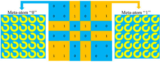
Figure 8.
Configuration of 1-bit coding metasurface (CM) with meta-atoms of ‘1’ and ‘0’.
RCS Reduction of Planar Coding Metasurface
Figure 8 depicts a planar MS array with 30 × 30-unit cells to verify the performance of a proposed metasurface. The properties of RCS reduction are evaluated by simulating the proposed coding metasurface in the time domain using CST Microwave Studio. All boundaries during the simulation are configured to open add-space. Perhaps a plane wave is an incident along the negative z-axis at a distance of λ/4 from the MS. A metallic plate of the same size as the reference is employed for the investigations. The monostatic RCS results of a composed 1-bit CM with a planar metallic slab of identical size under a normal incidence y-polarized wave are shown in Figure 9a. It is worth noting that the proposed coding metasurface effectively achieves more than 10 dB of radar cross-section reduction in the frequency range of 13.1–13.8 GHz and 20.4–30.9 GHz, with a maximum radar cross-section reduction value of 28 dB. The frequency ranges that the RCS decreases roughly correspond to those of meta-atoms ‘0’ and ‘1’, where the PCR is higher. A maximum radar cross-section reduction is also observed in the frequency range of 13.1–13.8 GHz and 20.4–30.9 GHz, according to proper polarization conversion ratio conditions. Moreover, we investigate the normalized monostatic RCS reduction for different polarization states, as shown in Figure 9b. The designed structure has the same response for all polarization states, indicating that it is polarization-insensitive, which is essential for practical applications. To learn more about the radar cross-section reduction technique, the far-field of the proposed 1-bit CM is simulated at 12.64, 23.32, and 26.06 GHz on the same scale as a metallic plate of the same size. Figure 10 shows the three-dimensional (3D) far-field scattering patterns under normal incidence.
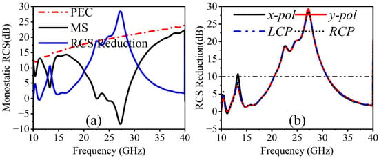
Figure 9.
(a) Monostatic RCS reduction of PEC and MS under a normal x-polarized wave, and (b) RCS reduction in different polarization states.
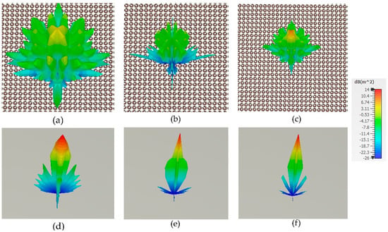
Figure 10.
Three-dimensional scattering performance of (a–c) coding metasurface and (d–f) PEC under normal incident x-polarized wave at 12.64, 23.32 GHz, and 26.06 GHz.
Figure 10d–f show the field distribution of a metallic plate at 12.64, 23.32, and 26.06 GHz, while Figure 10a–c show the field distribution of a 1-bit CM at the same frequency. The metallic plate exhibits a significant reflection lobe in the direction of the incident when electromagnetic waves impinge on it, while the coding metasurface exhibits a distribution of incident EM waves in all four directions due to destructive interference between lattices ‘0’ and ‘1’. Consequently, the direction of incidence will realize minimal reflection, leading to a significant decrease in the resultant radar cross-section. Nevertheless, the primary lobe in Figure 10a comprises the majority of the energy, which will reduce scattering performance at the central frequency. Due to its polarization-independent characteristics, the metasurface only considers the reduction in radar cross-section within various incident angles for the y-polarization direction. Figure 11 provides information on the performance of simulated radar cross-section reduction at various incident angles (θ = 0°, 10°, 20°, 30°, and 40°). Figure 11 shows the CM model’s RCS reduction performance increasing with the incident angle up to 40°. The achievement of a stable reduction in the radar cross-section across different angles is attained above 10 dB. At incident angles of 0°, 20°, 30°, and 40°, the corresponding bandwidth of the radar cross-section reduction shifts to the high-frequency band. At an incident angle of 10°, it moves to the lower-frequency band. This means that the coding metasurface model exhibits good wide-angle characteristics.
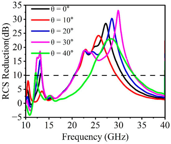
Figure 11.
RCS reduction of 1-bit coding metasurface at different incident angles (θ°).
6. Experimental Results
To experimentally validate the properties of the designed 1-bit CM, 5 × 5 lattices with a total size of 180 × 180 mm2 were fabricated, as illustrated in Figure 12a. Printed circuit technology was employed to etch metallic copper patterns onto the thin layer of the Rogers RT5880 substrate. The Rogers RT5880 layer had a thickness of 0.127 mm, while the metal layer was 35 µm thick. On the back side of the substrate, which includes an air gap, a metallic copper plate was employed to achieve complete reflection. The measurements were conducted in an anechoic chamber to eliminate environmental noise and reflections, ensuring precise results, as depicted in Figure 12b.
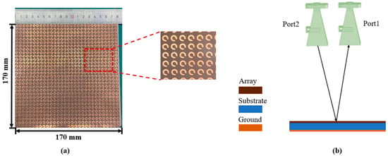
Figure 12.
(a) Prototype of 1-bit CM, and (b) experimental setup.
The reflected waves were measured using two different sets of linearly polarized horn antennas, covering two frequency sweeps (8–18 GHz and 18–40 GHz). These antennas were connected to an Agilent vector network analyzer N5230. The antennas’ centers should align with the center of the sample for accurate measurements. In order to calculate LP–CP conversion, it is necessary to measure both the co-polarized and cross-polarized reflection coefficients. Hence, two horn antennas were aligned in the same orientation, either vertically (y-polarized) or horizontally (x-polarized), to measure the co-reflection coefficient. For measuring the cross-reflection coefficient, the transmitting antenna was placed vertically, while the receiving antenna was positioned horizontally. Figure 13a illustrates the conversion performance of a planar CM from linear polarization to circular polarization under normal incident waves. From Figure 13a, it is evident that an axial ratio of less than 3 dB is achieved within different frequency ranges of 11.80–12.29, 13.17–18.44, and 33.33–40.35 GHz. Additionally, the axial ratio values remain consistently below 3 dB in the frequency bands, as mentioned above. Nevertheless, in monostatic RCS measurement, it is necessary to maintain a separation of over 2 m between the antennas and the sample to fulfill the far-field condition. The angular separation between antennas must be kept under 5°. The gate–reflect–line calibration was employed to effectively filter out additional noise and interference from the surrounding environment. A metal sheet of the same size was also measured as a reference to determine the actual reduction in the radar cross-section. Figure 13b illustrates the simulated and measured results of the radar cross-section reduction for the planar surface. A reduction in the RCS of more than 10 dB is observed within a single frequency band, specifically from 13.1 to 13.80 and 20.4 to 30.9 GHz. The simulated and measured results show good agreement, but there was minimal impact on the radar cross-section reduction due to channeling and experimental effects. Nonetheless, minor discrepancies between the simulation and measurement results occur due to manufacturing and measurement errors, such as misaligned horn antennas and the finite number of unit cells in the MS structure.
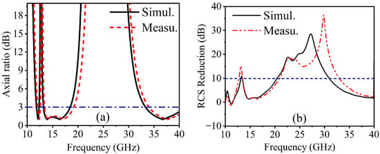
Figure 13.
Measured and simulated results of (a) (AR ≤ 3 dB) and (b) monostatic RCS reduction.
Table 1 compares the performance of the proposed metasurface with that of a recently published article. Our compact design achieves maximum linear polarization and linear-to-circular polarization conversion, as demonstrated by the data presented in Table 1. This dual-polarization capability with angular stability is a key feature of our design. In [35], the cited work exhibits good angular stability, although the polarization conversion ratio (PCR) falls below the proposed design. Additionally, these works operate within dual-frequency bands. The results indicate that the proposed structure performs well in both RCS reduction and LP-CP conversion.

Table 1.
Comparison of proposed metasurface with previously published paper.
7. Conclusions
This study introduces a dual-polarization conversion metasurface capable of achieving both cross-polarization and circular polarization conversion. It efficiently transforms linearly polarized electromagnetic waves into their orthogonal LP counterparts, achieving over 90% efficiency within single frequency bands ranging from 8.53 to 11.63 GHz, positioned at the center of LP-CP bands. Moreover, the metasurface achieves highly efficient LP–CP conversion within two sidebands spanning frequency ranges of 12.40 to 17.56 GHz. The aperiodic arrangement of meta-atoms within the coding metasurface minimizes backward scattering by redistributing reflected energies in various directions through reorientation. The proposed CM demonstrates consistent performance across different polarization states, exhibiting polarization insensitivity. This study introduces a concept for achieving LP–LP and LP–CP conversion, along with radar cross-section (RCS) reduction, showcasing potential applications in radar technology.
Author Contributions
Writing—original draft preparation, S.H.; software, S.H., methodology, S.H.; writing—review and editing, J.Y.; conceptualization, J.Y.; formal analysis, F.A.U.; data curation, Y.H.; validation, W.Y.; investigation, M.I. All authors have read and agreed to the published version of the manuscript.
Funding
This work is supported by the National Natural Science Foundation of China (No. 62127802), National Natural Science Foundation of China (No. 61821001).
Institutional Review Board Statement
Not applicable.
Informed Consent Statement
Not applicable.
Data Availability Statement
The datasets used and/or analyzed during the current study available from the corresponding author on reasonable request.
Conflicts of Interest
The authors declare no conflicts of interest.
References
- Ramachandran, T.; Faruque, M.R.I.; Islam, M.T.; Khandaker, M.U. Radar Cross-Section Reduction Using Polarization-Dependent Passive Metamaterial for Satellite Communication. Chin. J. Phys. 2022, 76, 251–268. [Google Scholar] [CrossRef]
- Yang, W.; Tam, K.; Choi, W.; Che, W.; Hui, H.T. Polarization rotation reflective surface based on the artificial magnetic conductor and its application. Electron. Lett. 2014, 50, 1500–1502. [Google Scholar] [CrossRef]
- Xiong, X.; Jiang, S.-C.; Hu, Y.-S.; Hu, Y.-H.; Wang, Z.-H.; Peng, R.-W.; Wang, M. Control the polarization state of light with symmetry-broken metallic meta structures. Ann. Phys. 2015, 358, 129–158. [Google Scholar]
- Chin, J.Y.; Lu, M.; Cui, T.J. Metamaterial polarizers by electric-field-coupled resonators. Appl. Phys. Lett. 2008, 93, 251903. [Google Scholar] [CrossRef]
- Zhao, Y.; Alù, A. Manipulating light polarization with ultrathin plasmonic metasurfaces. Phys. Rev. B 2011, 84, 205428. [Google Scholar] [CrossRef]
- Qin, F.; Ding, L.; Zhang, L.; Monticone, F.; Chum, C.C.; Deng, J.; Mei, S.; Li, Y.; Teng, J.; Hong, M.; et al. Hybrid bilayer plasmonic metasurface efficiently manipulates visible light. Sci. Adv. 2016, 2, e1501168. [Google Scholar] [CrossRef] [PubMed]
- Majeed, A.; Jinling, Z.; Khan, H.A.; Ishfaq, M.; Hayat, B. Multiband dual polarization conversion metasurface based on three-quarter circular-shape in the terahertz regime. Results Phys. 2024, 57, 107398. [Google Scholar] [CrossRef]
- Huang, Z.; Zheng, Y.; Li, J.; Cheng, Y.; Wang, J.; Zhou, Z.K.; Chen, L. High-resolution metalens imaging polarimetry. Nano Lett. 2023, 23, 10991–10997. [Google Scholar] [CrossRef]
- He, Y.; Cai, B.; Wu, L.; Chen, L.; Cheng, Y.; Chen, F.; Luo, H.; Li, X. Tunable VO2 metasurface for reflective terahertz linear and circular polarization wavefront manipulation at two frequencies independently. Phys. B Condens. Matter 2024, 681, 415848. [Google Scholar] [CrossRef]
- Sieber, P.E.; Werner, D.H. Infrared broadband quarter-wave and half-wave plates synthesized from anisotropic Bézier metasurfaces. Opt. Express 2014, 22, 32371–32383. [Google Scholar] [CrossRef]
- Khan, M.I.; Tahir, F.A. An angularly stable dual-broadband anisotropic cross-polarization conversion metasurface. J. Appl. Phys. 2017, 122, 053103. [Google Scholar] [CrossRef]
- Khan, M.I.; Fraz, Q.; Tahir, F.A. Ultra-wideband cross-polarization conversion metasurface insensitive to incidence angle. J. Appl. Phys. 2017, 121, 045103. [Google Scholar] [CrossRef]
- Ahmad, T.; Rahim, A.A.; Bilal, R.M.H.; Noor, A.; Maab, H.; Naveed, M.A.; Madni, A.; Ali, M.M.; Saeed, M.A. Ultrawideband cross-polarization converter using anisotropic reflective metasurface. Electronics 2022, 11, 487. [Google Scholar] [CrossRef]
- Khan, H.A.; Huang, C.; Xiao, Q.; Abbas, S.M. Polarization-dependent coding metasurface with switchable transmission and RCS reduction bands. Micromachines 2022, 14, 78. [Google Scholar] [CrossRef] [PubMed]
- Liu, Z.; Zhao, B.; Jiao, C.; Zhao, L.; Han, X. Broadband cross-polarization conversion metasurface based on cross-shaped resonators. Appl. Phys. A 2021, 127, 825. [Google Scholar] [CrossRef]
- Majeed, A.; Zhang, J.; Ashraf, M.A.; Memon, S.; Mohammadi, K.H.; Ishfaq, M.; Sun, M. An ultra-wideband linear-to-circular polarization converter based on a circular, pie-shaped reflective metasurface. Electronics 2022, 11, 1681. [Google Scholar] [CrossRef]
- Zheng, Q.; Guo, C.; Vandenbosch, G.A.E.; Yuan, P.; Ding, J. Dual-broadband Highly Efficient Reflective Multi-polarisation Converter Based on Multi-order Plasmon Resonant Metasurface. IET Microw. Antennas Propag. 2020, 14, 967–972. [Google Scholar] [CrossRef]
- Lin, B.; Huang, W.; Guo, J.; Wang, Y.; Zhu, R.; Ji, X. Dual-band and high-efficiency metasurface-based circular-to-linear polarization converter. PLoS ONE 2023, 18, e0286411. [Google Scholar] [CrossRef] [PubMed]
- Kundu, D.; Singh, J.; Singh, D.; Chakrabarty, A. Design and Analysis of Broadband Ultrathin Reflective Linear-to-Circular Polarization Converter Using Polygon-Based Anisotropic-Impedance Surface. IEEE Trans. Antennas Propag. 2021, 69, 5154–5159. [Google Scholar] [CrossRef]
- Majeed, A.; Zhang, J.; Awan, Z.A.; Memon, S.; Ishfaq, M.; Wang, C. A high-efficiency dual-band linear-to-circular polarization converter based on rectangular-slot reflective metasurface. Appl. Sci. 2022, 12, 9172. [Google Scholar] [CrossRef]
- Zheng, Q.; Guo, C.; Ding, J. Wideband Metasurface-Based Reflective Polarization Converter for Linear-to-Linear and Linear-to-Circular Polarization Conversion. Antennas Wirel. Propag. Lett. 2018, 17, 1459–1463. [Google Scholar] [CrossRef]
- Greco, F.; Arnieri, E. Dual-frequency linear-to-circular polarization converter for ka-band applications. Sensors 2022, 22, 2187. [Google Scholar] [CrossRef] [PubMed]
- Gao, X.; Li, K.; Wu, X.; Xue, C.; Wang, G.; Xie, X.; Qin, M. Ultra-wideband linear-to-circular polarizer realized by bi-layer metasurfaces. Opt. Express 2022, 30, 18392–18401. [Google Scholar] [CrossRef] [PubMed]
- Gao, X.; Yang, W.L.; Ma, H.F.; Cheng, Q.; Yu, X.H.; Cui, T.J. A Reconfigurable Broadband Polarization Converter Based on an Active Metasurface. IEEE Trans. Antennas Propag. 2018, 66, 6086–6095. [Google Scholar] [CrossRef]
- Dutta, R.; Ghosh, J.; Yang, Z.; Zhang, X. Multi-Band Multi-Functional Metasurface-Based Reflective Polarization Converter for Linear and Circular Polarizations. IEEE Access 2021, 9, 152738–152748. [Google Scholar] [CrossRef]
- Khan, M.I.; Khalid, Z.; Tahir, F.A. Linear and circular-polarization conversion in X-band using anisotropic metasurface. Sci. Rep. 2019, 9, 4552. [Google Scholar] [CrossRef] [PubMed]
- Wahidi, M.S.; Khan, M.I.; Tahir, F.A.; Rmili, H. Multifunctional single layer metasurface based on hexagonal split ring resonator. IEEE Access 2020, 8, 28054–28063. [Google Scholar]
- Wang, X.; Du, Z.; Hou, M.; Ding, Z.; Jiang, C.; Huang, X.; Yue, J. Design method of structural microwave absorber by frequency characteristic analysis of reflectivity function. Opt. Commun. 2022, 510, 127885. [Google Scholar] [CrossRef]
- Song, J.; Wu, X.; Huang, C.; Yang, J.; Ji, C.; Zhang, C.; Luo, X. Broadband and tunable RCS reduction using high-order reflections and Salisbury-type absorption mechanisms. Sci. Rep. 2019, 9, 9036. [Google Scholar] [CrossRef]
- Li, W.; Zhang, Y.; Wu, T.; Cao, J.; Chen, Z.; Guan, J. Broadband radar cross section reduction by in-plane integration of scattering metasurfaces and magnetic absorbing materials. Results Phys. 2019, 12, 1964–1970. [Google Scholar] [CrossRef]
- Munk, B.A.; Munk, P.; Pryor, J. On designing Jaumann and circuit analog absorbers (CA absorbers) for oblique angle of incidence. IEEE Trans. Antennas Propag. 2007, 55, 186–193. [Google Scholar] [CrossRef]
- Zhang, Y.; Miao, L.; Guo, S.; Huang, Z.; Cao, Z.; He, Y.; Wei, J.; Li, C.; Jiang, J. A broadband tunable frequency selective surface absorber for oblique incidence applications. J. Phys. D Appl. Phys. 2019, 53, 055105. [Google Scholar] [CrossRef]
- Li, S.J.; Li, Y.B.; Zhang, L.; Luo, Z.J.; Han, B.W.; Li, R.Q.; Cao, X.Y.; Cheng, Q.; Cui, T.J. Programmable Controls to Scattering Properties of a Radiation Array. Laser Photonics Rev. 2021, 15, 2170016. [Google Scholar] [CrossRef]
- Gao, Z.; Fan, Q.; Tian, X.; Xu, C.; Meng, Z.; Huang, S.; Xiao, T.; Tian, C. An optically transparent broadband metamaterial absorber for radar-infrared bi-stealth. Opt. Mater. 2021, 112, 110793. [Google Scholar] [CrossRef]
- Li, F.; You, B. Complementary multi-band dual polarization conversion metasurface and its RCS reduction application. Electronics 2022, 11, 1645. [Google Scholar] [CrossRef]
- Ameri, E.; Esmaeli, S.H.; Sedighy, S.H. Ultra-Wideband Radar Cross Section Reduction by Using Polarization Conversion Metasurfaces. Sci. Rep. 2019, 9, 478. [Google Scholar] [CrossRef] [PubMed]
- Cui, T.J.; Qi, M.Q.; Wan, X.; Zhao, J.; Cheng, Q. Coding metamaterials, digital metamaterials and programmable metamaterials. Light Sci. Appl. 2014, 3, e218. [Google Scholar] [CrossRef]
- Huang, C.; Pan, W.; Ma, X.; Luo, X. Multi-spectral metasurface for different functional control of reflection waves. Sci. Rep. 2016, 6, 23291. [Google Scholar] [CrossRef]
Disclaimer/Publisher’s Note: The statements, opinions and data contained in all publications are solely those of the individual author(s) and contributor(s) and not of MDPI and/or the editor(s). MDPI and/or the editor(s) disclaim responsibility for any injury to people or property resulting from any ideas, methods, instructions or products referred to in the content. |
© 2024 by the authors. Licensee MDPI, Basel, Switzerland. This article is an open access article distributed under the terms and conditions of the Creative Commons Attribution (CC BY) license (https://creativecommons.org/licenses/by/4.0/).