Article

Polarization-Based Reflection Suppression Method and Its Application to Target Detection

1
Research Institute of Changchun University of Science and Technology in Chongqing, Changchun 130012, China
2
School of Electronics and Information Engineering, Changchun University of Science and Technology, Changchun 130012, China
3
Institute of Space Optoelectronics Technology, Changchun University of Science and Technology, Changchun 130012, China
*
Author to whom correspondence should be addressed.
Photonics 2024, 11(5), 445; https://doi.org/10.3390/photonics11050445
Submission received: 8 March 2024 / Revised: 19 April 2024 / Accepted: 7 May 2024 / Published: 10 May 2024
(This article belongs to the Section Optical Interaction Science)

Abstract

:
Active illumination light becomes strongly reflective interference light after specular reflection. It causes saturation in some areas of the image during target detection, resulting in the inability to recognize detailed target feature information. This greatly limits the application of active illumination detection. Based on the Mueller matrix analysis of the difference in polarization characteristics between the background specular reflected light and the target reflected light, we propose a reflection suppression method based on orthogonal polarization imaging. The method employs a polarization modulation strategy in a bidirectional manner between the light source and the detector. First, the polarization information difference is amplified by active polarized illumination between the background specular reflected light and the target reflected light. Then, the target recovery is achieved by suppressing the background specular reflected light through the polarized orthogonal imaging method. Meanwhile, this method can also be used for moving target detection. The experimental results show that the reflection suppression method of orthogonal polarization imaging can effectively suppress the interference of specular reflection on the target image. Additionally, it can reduce the problems of missed and false detection that occurs in moving target detection and improve the active illumination detection effect.

1. Introduction

Conventional photoelectric imaging detection techniques distinguish targets by the value of the difference between the reflected or radiated intensity of the target and the background [1]. The reflected light from the target can be increased by active illumination in scenes with insufficient natural light. However, in the active imaging process, many bright light points are produced due to specular reflection on the smooth background surface. The integration of a large number of light points creates a spot with high radiant energy [2,3,4,5]. It tends to lead to saturation of large areas of pixels in the image and is a very strong source of interference for photoelectric imaging detection.
Researchers are forced to recognize target feature information in reflective regions when using active illumination on a smooth background surface. Faced with the strong light signal formed by specular reflection, previous studies have avoided the background specular reflection by constantly adjusting the intensity of the incident light source or the detection angle. This greatly limits the practicability and poses a great challenge for some scientific studies. Polarization imaging detection is a detection technique based on the difference between the polarization characteristics of the target and the background. It adopts reasonable technical means to improve the recognition of target detail feature information through the different polarization feature information of the target and background [6,7,8]. Studies indicate that incident light has significant polarization characteristics after specular reflection [9,10]. Based on this, Yang designed a time-sharing infrared polarization imaging system for moving target detection [11]. The system acquires images of infrared radiation intensity in different polarization directions of the target by rotating the polarizer continuously and rapidly. However, it has limited applicability to target detection under strong reflected light interference. Zhu designed an adaptive polarization detection system for sea surface targets [12]. The system provides real-time polarization detection of sea surface targets and effectively improves artifacts in images. However, this system cannot effectively suppress the strong flare background using only one polarizer. Ye proposed utilizing the time-domain polarization property of the solar scintillation characteristics to perform time-domain fusion through the generated multi-frame spatial domain sun glint suppression images [13]. However, this method cannot satisfactorily suppress the sun glint in real time. When there is a change in the relative position of the target, the target and background may be misjudged during detection, resulting in the loss of target information.
To address the problem of strong reflected light interfering with target detection, we first analyze the polarization characteristics of specularly reflected light and refracted light. Secondly, we analyze the different depolarization characteristics between the target and background through Mueller matrix polarization decomposition. According to the difference in depolarization characteristics between the target and background, a polarization reflection suppression system is designed. The system amplifies the polarization information difference between the background specular reflected light and the target reflected light by using active polarized illumination through the polarization modulation strategy in both directions of the light source and the detector. The polarization direction of the polarization state analyzer (PSA) in front of the detector is adjusted according to the polarization direction of the polarization state generator (PSG) in front of the light source to achieve effective suppression of reflections. This method is not only suitable for detecting stationary targets but can also be applied to detecting moving targets. In this paper, the polarization reflection suppression method is combined with the moving target detection method, which effectively reduces the missed and false detection problems during the moving target detection, and improves the accuracy of the moving target detection algorithm. The method in this paper is expected to provide more powerful technical support for target detection in more active light illumination scenarios.

2. Polarization Reflection Suppression Method

2.1. Analysis of Polarization Characteristics of Reflected and Refracted Light

Light can be decomposed into S-polarized light perpendicular to the plane of incidence and P-polarized light parallel to the plane of incidence. According to Fresnel’s law of reflection, incident light irradiated on a smooth background surface is reflected and refracted. The spatial plane formed by the incident, reflected, and refracted light is shown in Figure 1.
The reflectance and refractive indices can be used as physical quantities to characterize the conversion relationship between incident, reflected, and refracted light radiation energy. It allows a physical description of the optical transmission process. The reflectance and refractive indices in parallel and perpendicular directions are the following:
R s = ( n 1 cos θ i n 2 cos θ t n 1 cos θ i + n 2 cos θ t ) 2 R p = ( n 2 cos θ i n 1 cos θ t n 2 cos θ i + n 1 cos θ t ) 2
T s = n 2 cos θ t n 1 cos θ i 4 sin 2 θ t cos 2 θ i sin 2 ( θ i + θ t ) T p = n 2 cos θ t n 1 cos θ i 4 sin 2 θ t cos 2 θ i sin 2 ( θ i + θ t ) cos 2 ( θ i θ t )
where R s and T s are the reflectance and refractive indices of S-polarized light, R p and T p are the reflectance and refractive indices of P-polarized light, n 1 and n 2 are the refractive indices of the medium, θ i is the angle between the incident light and the normal, and θ t is the angle between the refracted light and the normal.
According to Snell’s law, the refractive index of a medium is related to the angle of incidence and the angle of refraction:
n 1 n 2 = sin θ t sin θ i
The degree of polarization of reflected and refracted light is directly related to the magnitude of the angles of incidence and refraction, which is calculated by the following equation:
P r = I r s I r p I r s + I r p = cos 2 ( θ i θ t ) cos 2 ( θ i + θ t ) cos 2 ( θ i θ t ) + cos 2 ( θ i + θ t ) P t = I t s I t p I t s + I t p = 1 cos 2 ( θ i + θ t ) 1 + cos 2 ( θ i + θ t )
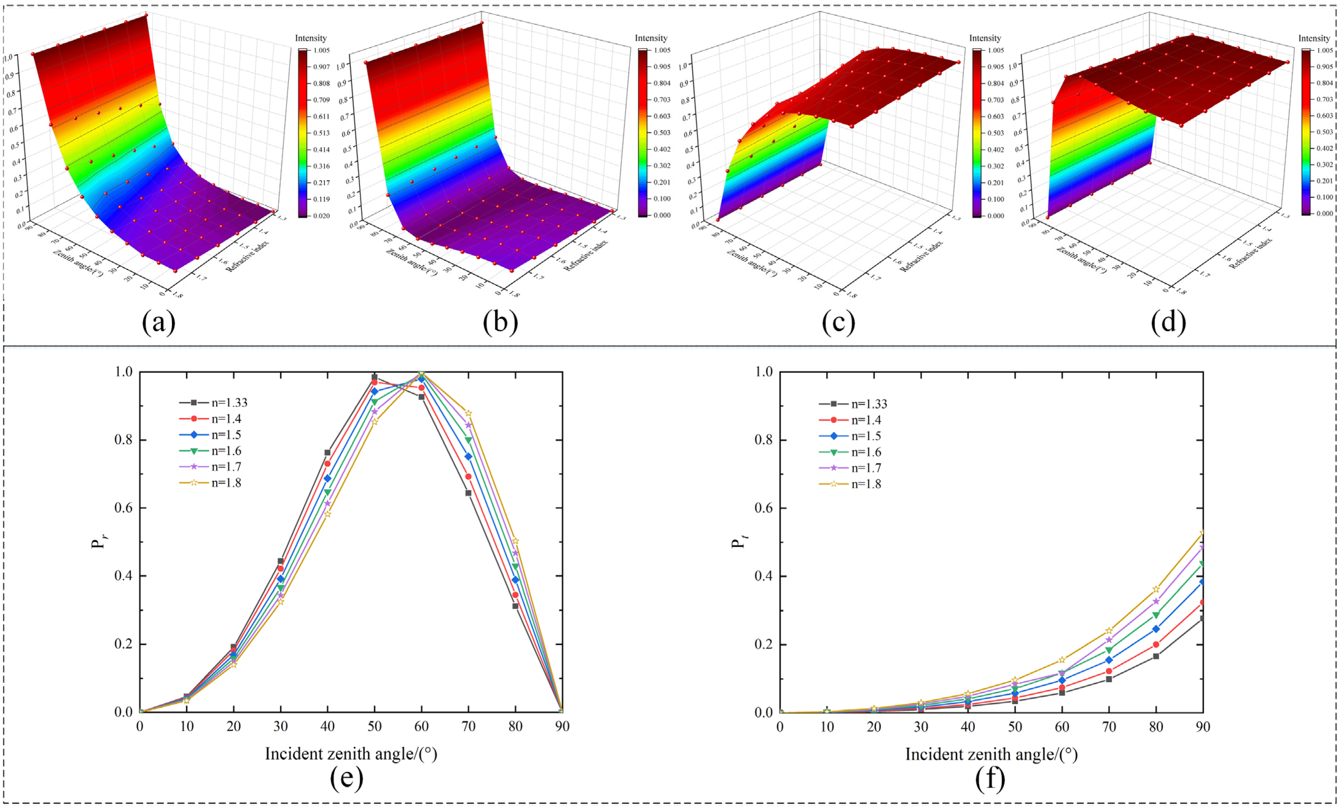
Since the change in polarization characteristics is closely related to the refractive index of the medium, in order to compare the change in polarized light characteristics when the incident light is reflected and refracted on the surface of the medium with different refractive indices, we set the incident zenith angle to be 0° to 90°, the refractive index of the air to be one, air n 1 to be one, and the refractive index of the medium n 2 to be set in the interval of 1.33 to 1.8 in our simulation calculations [14]. The refractive index of water is 1.33, and the refractive index of glass is 1.5. Combining Equations (1), (2), and (4) to visualize the relationship curves of the incident zenith angle, reflectance, refractive index, the degree of polarization of the reflected light, and the degree of polarization of the refracted light, is shown in Figure 2.
As shown in Figure 2, the degree of polarization of the reflected light under different refractive index media all show a tendency to increase and then decrease. The maximum value of the degree of polarization of the reflected light corresponds to the incident zenith angle being the Brewster angle. At this time, the polarization information of the P component is zero, and only the polarization information of the S component remains. The polarization information of the S component of the reflected light can be suppressed by using a parallel polarizer. However, when light is incident at a non-Brewster angle, the S component of the reflected light does not have the absolute advantage in terms of the main polarization direction information. In this case, the suppression of reflections by parallel polarizers will be very inefficient [15].

2.2. Polarization Decomposition of Mueller Matrices

The 16 elements of the Mueller matrix have different physical meanings. It allows the numerical conversion of a complex physical process involving the depolarization of the medium, bidirectional attenuation, phase delay, and other relevant physical parameters [16]. Bidirectional attenuation is the intensity decay associated with polarization, and phase delay is the phase change associated with polarization, and they represent the process of polarized light transforming from one type of fully polarized light to another type of fully polarized light. Depolarization can quantify the value of the degradation of fully polarized light into partially polarized light, and the depolarization characteristics of the target that differ from the background can be derived by analyzing the Mueller matrix polarization decomposition image. The Mueller matrix is expressed as the following:
M = M 11 M 12 M 13 M 14 M 21 M 22 M 23 M 24 M 31 M 32 M 33 M 34 M 41 M 42 M 43 M 44
where M 11 denotes the light intensity information of the transmission medium, M 12 , M 13 , M 14 denote the bidirectional attenuation characteristics of the transmission medium, M 21 , M 31 , M 41 denote the polarization-generating characteristics of the transmission medium, M 22 , M 33 , M 44 denote the depolarization characteristics of the transmission medium, and M 23 , M 24 , M 32 , M 34 , M 42 , M 43 denote the phase delay characteristics of the transmission medium, respectively.
According to the Lu–Chipman polarization decomposition method [17], Mueller matrix polarization decomposition is expressed as the product of three physical polarization effect coefficients, namely, depolarization matrix M Δ , phase delay matrix M R , and bidirectional attenuation matrix M D . The normalized Mueller matrix expression is given by the following:
M = M 11 1 m 12 m 13 m 14 m 21 m 22 m 23 m 24 m 31 m 32 m 33 m 34 m 41 m 42 m 43 m 44 = M Δ M R M D
m i j = M i j M 11 , i , j = 1 , 2 , 3 , 4
The bidirectional attenuation coefficient, the phase delay coefficient, and the depolarization coefficient can be calculated from the Mueller matrix elements. The bidirectional attenuation coefficient D is expressed as the following:
D = m 12 2 + m 13 2 + m 14 2 , ( 0 D 1 )
The phase delay coefficient R is expressed as the following:
R = arccos t r ( M R ) 2 1
The depolarization coefficient Δ is expressed as the following:
Δ = 1 m 22 + m 33 + m 44 2 , 0 Δ 1
The active illumination light is specularly reflected and refracted to produce linearly polarized light, while also producing a small component of circularly polarized light. Therefore, only the linear polarization component generally needs to be considered in Mueller imaging. Studies in the literature [18] have shown that the depolarization parameters of different media can be defined using linear polarization measurements as well as full polarization measurements. Linear polarization measurements are more convenient than full polarization measurements in practice. In this paper, a combination of 16 different polarization state generation and polarization state analysis methods has been adopted to acquire Mueller matrix images. The Mueller matrix with four rows and four columns is simplified to a Mueller matrix with three rows and three columns. It is shown as follows:
M = M 11 M 12 M 13 M 21 M 22 M 23 M 31 M 32 M 33 = I 11 + I 12 + I 21 + I 22 I 11 + I 12 I 21 I 22 I 31 + I 32 I 43 I 44 I 11 + I 21 I 12 I 22 I 11 + I 22 I 12 I 21 I 31 + I 42 I 32 I 41 I 13 + I 23 I 14 I 24 I 13 + I 24 I 14 I 23 I 33 + I 44 I 34 I 43
where I denotes the target light intensity images collected by the detector under different combinations of PSG and PSA. The line-polarized light at 0° and 90° is denoted by numbers 1 and 2. The line-polarized light at 45° and 135° is denoted by numbers 3 and 4.
In this paper, we focus on the difference between the depolarization characteristics of the target and the background, so we need to analyze the depolarization characteristics of the target and the background by Mueller matrix polarization decomposition. The linear depolarization matrix Δ L is expressed as the following:
Δ L = 1 m 22 + m 33 2 , 0 Δ L 1
When Δ L = 0 , this indicates that the reflected light from the target has retained the polarization state imparted by the incident light. When Δ L = 1 , this indicates that the target reflected light loses the polarization state imparted by the incident light. When 0 < Δ L < 1 , this indicates that the target is partially depolarized.

2.3. Reflection Suppression Method for Orthogonal Polarization Imaging

The polarization state of light can be represented by the Stokes coefficients S 0 , S 1 , and S 2 . The Stokes parameter of the incident light can be represented as the following:
S = S 0 S 1 S 2 = I 0 o + I 90 o I 0 o I 90 o I 45 o I 135 o
where I 0 o , I 45 o , I 90 o , and I 135 o represent polarized images with polarization directions of 0°, 45°, 90°, and 135°, respectively. The parameter S 0 is the total light intensity. The parameter S 1 is the difference between the light intensity of the 0° and 90° linear polarization components. The parameter S 2 is the difference between the light intensity of the 45° and 135° linear polarization components.
According to Marius’ law, polarized light can be decomposed into natural light and fully polarized light. The intensity of light received by the detector after passing through the PSA is given by the following equation:
I α = I N α + I P α = 1 2 I N + I P cos 2 ( α A )
where α is the angle of polarization state generation of the light, I α is the polarized light intensity value corresponding to the angle of polarization state generation α , I N α is the natural light intensity value corresponding to the angle of polarization state generation α , I P α is the fully polarized light intensity value corresponding to the angle of polarization state generation α , I N is the natural light intensity value in the polarized light, I P is the fully polarized light intensity value of the polarized light, and A is the angle of polarization of the PSA. The target reflected light information contained in the reflected light information received by the detector is regarded as beneficial light intensity information. The fully polarized light information contained in the reflected light information is regarded as interference light intensity information.
Extracting the fully polarized light in I p , the above Equation (14) simplifies to the following:
I p = 2 I α I N 2 cos 2 ( α A )
Equation (15) can be analyzed to show that when α = A ± k π , the detector receives not only natural light but also fully polarized light. At the same time, the fully polarized light intensity value reaches its maximum, and the detector receives the maximum value of the interfering light intensity. When α = A ± π / 2 , the detector receives only natural light. At this time, the value of the intensity of the interfering light received by the detector reaches its minimum, as shown in Equation (16):
I α = 1 2 I N + I P , α = A ± k π 1 2 I N , α = A ± π / 2
The presence of fully polarized light is the main reason why mirror reflections cannot be completely suppressed. When suppressing reflections, it is necessary to ensure that the polarization state generation angle α is orthogonal to the polarization state analysis angle A as much as possible. In active illumination, the polarization state generation angle α of the PSG can be freely defined. At the same time, the polarization analysis angle of the PSA can be adjusted adaptively. Therefore, the polarization state generation angle α and the polarization state analysis angle A are known quantities that can be controlled by the system.

3. Experiment on Polarization Reflection Suppression

3.1. Analysis of Mueller Matrix Characteristics

When conducting Mueller matrix experiments, light may be scattered or absorbed during transmission. The Mueller matrix can comprehensively characterize the modification of the polarization properties of incident light by the transmission medium. The literature [19] shows that the depolarization image obtained by Mueller matrix polarization decomposition is insensitive to inhomogeneous illumination, and it only depends on the transmission medium. When the amount of scattering occurring in the transmission process of light increases, the degree of depolarization also increases, but the degree of depolarization of the target and the background still has obvious differences. The difference in polarization information between the target reflected light and the background reflected light can still be distinguished by the depolarization image, and the difference in polarization information between the target and the background can be utilized to improve the saliency of the target. In addition, when conducting Mueller matrix experiments outdoors, there are several situations that need to be specially considered: (1) When acquiring Mueller matrix images, it is necessary to ensure that the relative position of the target does not change during the acquisition process. (2) While ensuring the stability of the light source, the effect of the length of the exposure time on the imaging needs to be taken into account. (3) During the acquisition process, the weather, the transmission medium, and the location of the target need to be kept constant, and too many uncertainties should not be introduced into the experiment. These uncertainties can lead to unstable experimental data and increased errors, ultimately leading to inaccurate results. Because there are too many uncontrollable factors in the outdoor Mueller matrix imaging experiments, in order to ensure the accuracy of the Mueller matrix experimental results, and to reduce the difficulty of acquiring Mueller matrix images, we conducted the Mueller matrix imaging experiments in an indoor controlled environment. It is ensured that the environmental factors remain constant during the acquisition process, and the interference of the experimental results due to the change in environmental factors is excluded, while the target of the acquisition is selected as a stationary target. To reflect the scientific nature of the experiment, the target is divided into two categories according to the different roughness of the target surface. One category is targets with relatively rough surfaces, such as tennis balls and grass. The reflected light from this type of experimental object is mainly diffuse light. The other category is targets with relatively smooth surfaces, such as metal materials. The reflected light from this type of experimental object is mainly specular reflected light. Two types of targets are placed in a glass box to simulate stationary targets that need to be detected, and the specular reflection light formed by the specular reflection of the glass box is used as the main interference light in the experiment.
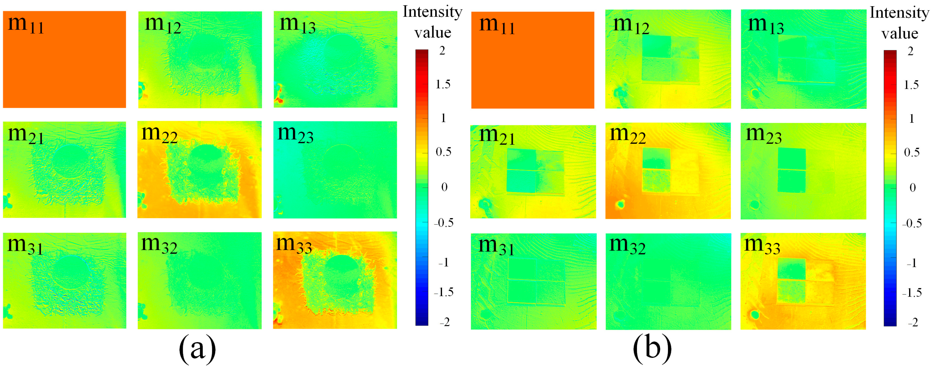
In this paper, 16 polarization images acquired with different combinations of polarization state generation and polarization state analysis are calculated by Equation (11) to obtain the linear Mueller matrix image, as shown in Figure 3. The different intensity values in Figure 3 reflect the intensity differences between different pixels in the Mueller matrix parameters, and the target and background can be distinguished by the intensity differences between pixels.
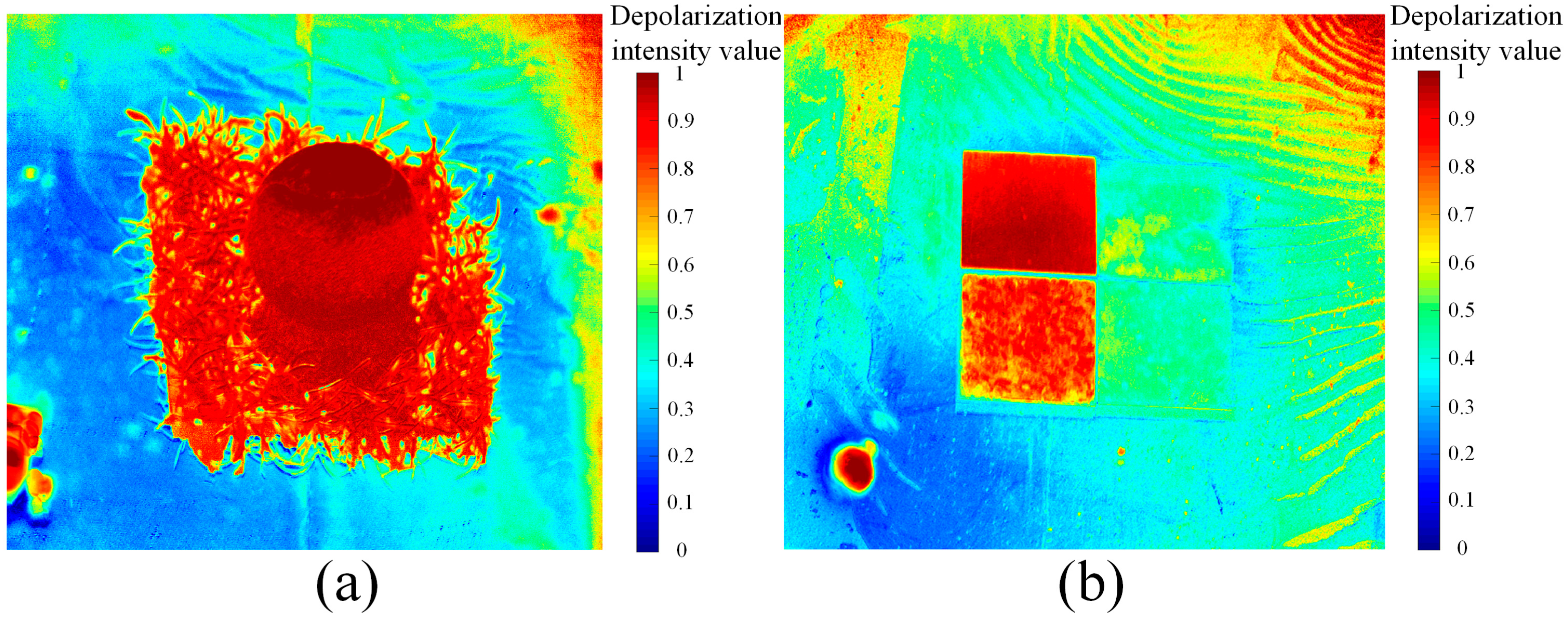
In Figure 3, it can be seen that there is a significant difference between the images of the diagonal elements m22 and m33 of the Mueller matrix and the images of other matrix elements. The m22 and m33 images are the most sensitive to the distinction between the target and the background, contributing more information about the detailed features of the target compared to the other matrix elements. A similar pattern is presented on the Mueller matrix images of these two different types of targets. By analyzing Equation (11), it can be seen that m22 and m33 are generated by subtracting the orthogonal image from the image parallel to the PSG and PSA directions. In images where the PSG is parallel to the PSA direction, both the target and the background have high light intensity values. In images where the PSG is orthogonal to the PSA direction, the target has a high light intensity value, and the background has a relatively low light intensity value. When the image in the orthogonal direction of PSG and PSA is subtracted from the image in the parallel direction of PSG and PSA, the light intensity value of the background decreases less, while the light intensity value of the target decreases more. It also verifies the phenomenon that the intensity value of the target image is lower than the intensity value of the background image in Figure 3. We further calculate the depolarization image of Mueller matrix polarization decomposition by Equation (12), as shown in Figure 4. The different depolarization intensity values in the figure reflect the different degrees of depolarization of the target and the background.
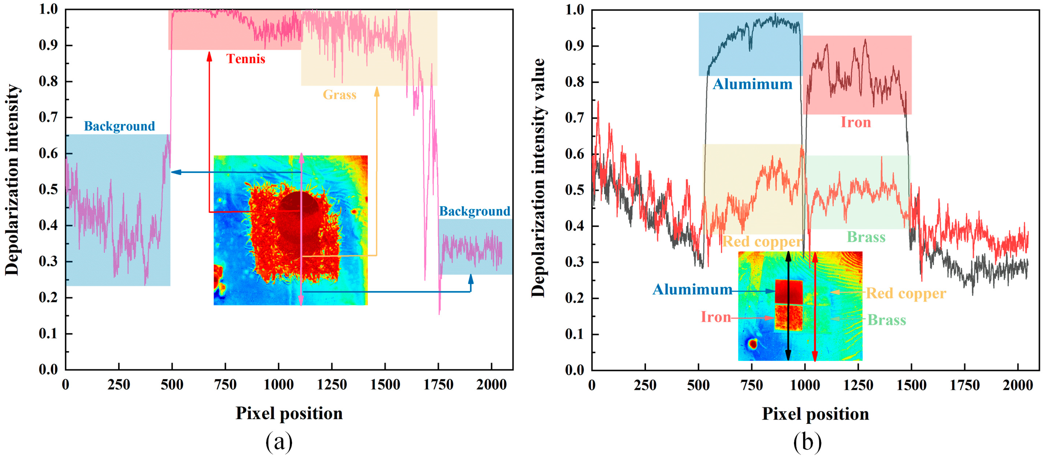
To analyze the different depolarization characteristic laws of the target and the background, we decomposed the depolarization intensity values of the two depolarized images in Figure 4. The two different target depolarization intensity value curves are plotted, as shown in Figure 5.
As can be seen in Figure 5, the depolarization intensity values of the targets are significantly higher than those of the background, and the trends of the depolarization intensity values of different targets are also quite different. In the index of depolarization intensity values, the tennis ball and grass increased by 0.531 on average compared to the background, and the metallic material increased by 0.306 on average compared to the background. This shows that both types of targets produced an obvious depolarization phenomenon. The specular background has better polarization preserving properties relative to these two types of targets. The phenomenon of depolarization of the reflected light from the target is caused by the primary transmission of the incident polarized light through the glass surface, the diffuse scattering caused by the roughness of the target surface, and the secondary transmission of the reflected light of the target through the glass surface. This eventually causes a polarization information difference between the target and the specular background. Also, the background reflected light appears partially depolarized. This is because the background is partially wrinkled in the experiment causing multiple scattering of the reflected light from the background, so the background is partially depolarized. In reality, specular backgrounds such as glass or water tend to be smoother, so the specular background is better able to retain the original polarization state of the incident light. Therefore, the difference in polarization information between the specular background and the target will be more pronounced.

3.2. Analysis of Experimental Results on Polarization Reflection Suppression

Images may become saturated during active illumination detection due to specular reflections, and adjusting the exposure time to reduce the saturation of the image is a common method. When active illumination light is used for target detection on a smooth background surface, the following problems may be experienced: (1) When the intensity of the light source is higher, more light signals reflected from the target can be obtained during imaging, but some areas of the image appear to be oversaturated. When the exposure time is turned down, the saturation of the brighter parts of the image is controlled, but it may lead to the loss of details in the darker parts of the image, resulting in a lack of clarity in the detailed features of the target. (2) When the intensity of the light source is low, the reflected light signal of the target obtained during imaging is relatively small. When the exposure time is increased, it may cause blurring of the moving target when the moving target is faster, or the camera tracking speed is slower, which reduces the clarity of the image and the accuracy of target recognition. Based on the above problems, our study aims to ensure that the detailed features of the target are clear during the imaging process under the relatively strong reflected light of the target, and not to cause loss of image information due to the excessive intensity of the light source.
According to Section 3.1, it can be seen that the target and the specular background have different depolarization characteristics, so the target reflected light and the background specular reflected light have obvious polarization information differences. Amplifying this polarization information difference and suppressing the background information through reasonable technical means become the preferred technical route to suppress the reflection method. In this paper, tennis balls, grass, metal, books, dolls, and water cups are selected as experimental targets. At the same time, common transparent media which easily transmit specular reflection and refraction are selected as the background, such as glass boxes and water tanks. In this paper, DAHENG IMAGING’s division of focal plane (DoFP) polarization camera and a visible light intensity camera with a polarizer were selected for the experiments. A total of five scenes were selected for experimental comparison, with scenes 1 and 2 taken by the visible light intensity camera and scenes 3, 4, and 5 taken by the DoFP camera. The light sources are divided into unpolarized illumination light source and polarized illumination light source. For polarized illumination light sources, this paper sets the polarization direction of the polarizer at 0°. There is no specificity in this polarization direction, and similar reflection suppression effects can be achieved using illumination light sources with other polarization directions.
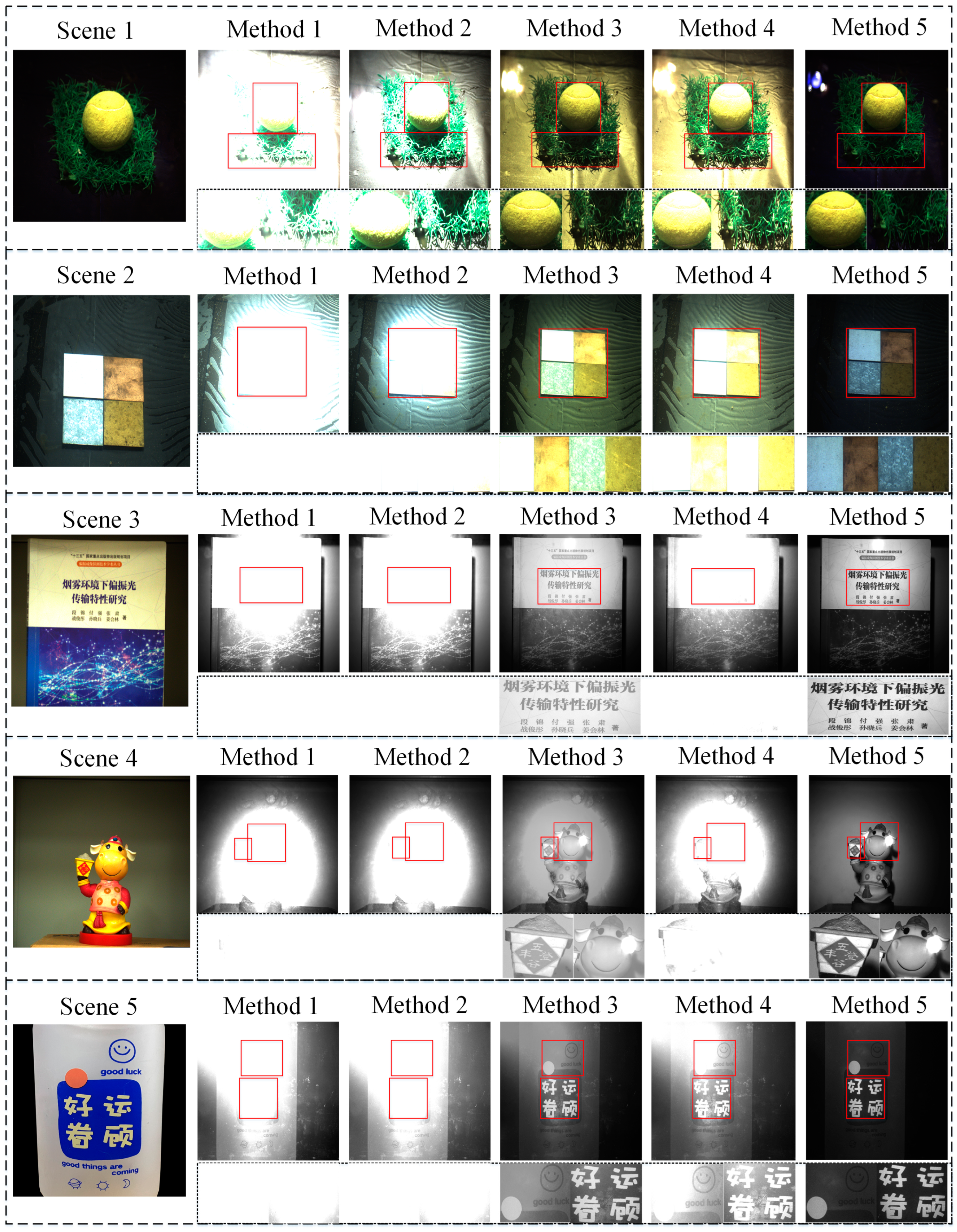
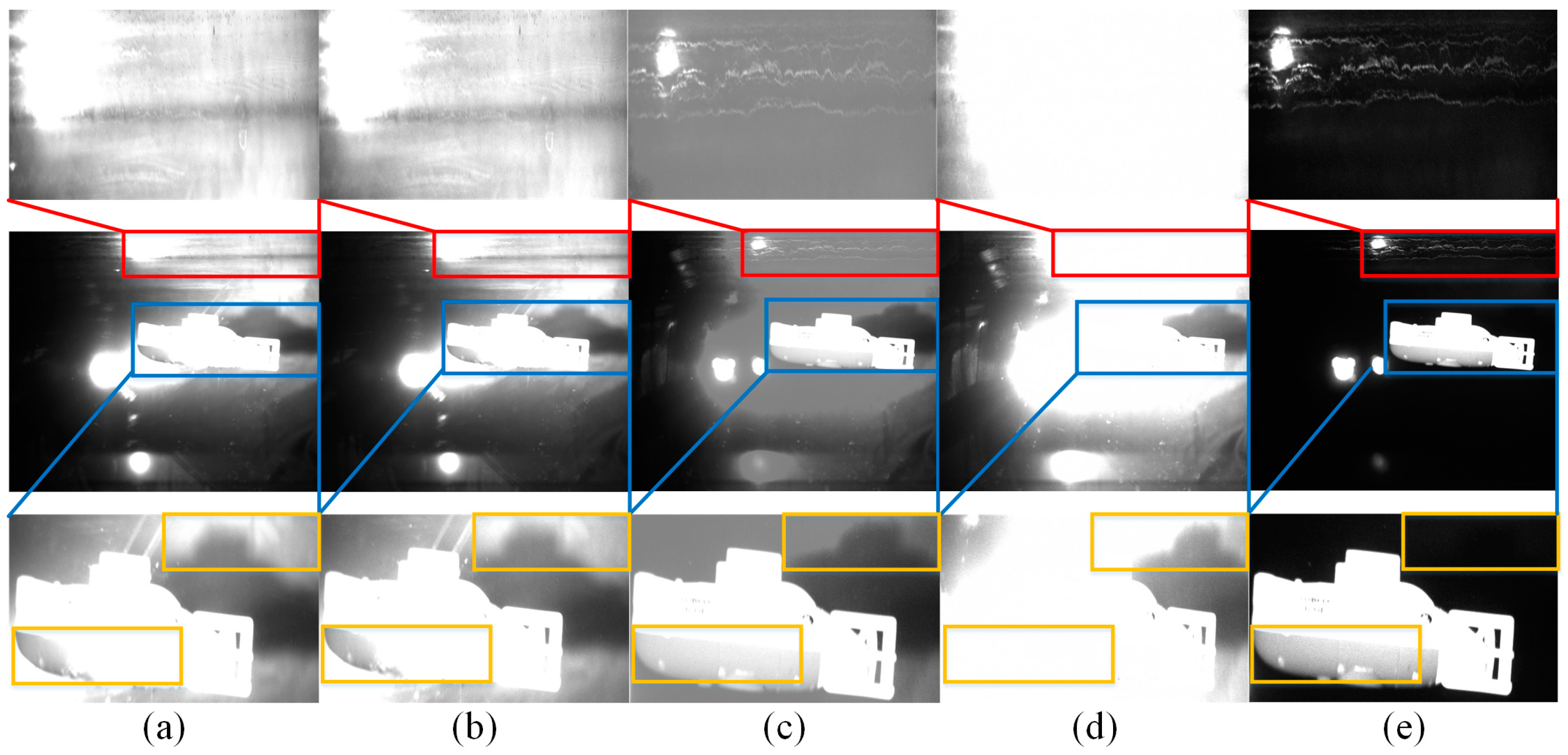
We compared the image detail features under different imaging methods in parallel and simplified the names of the different imaging methods. We define light intensity imaging under unpolarized illumination as method 1, which aims to acquire a target image under unpolarized illumination. We define 90° polarization imaging under unpolarized illumination as method 2, which aims to suppress the S-polarized component of the background specular reflection using a polarizer, and it is also the common reflection suppression method used by current researchers. We define S 0 imaging under polarized illumination light as method 3, which aims at acquiring target images under active polarized illumination. It is important to note that although installing a polarizer in front of the light source reduces the intensity of the illumination, the strong ability to maintain the polarization characteristics can be exploited in complex transmission environments to increase the effective detection distance. The active polarization detection method can better highlight the scene detail information and improve the contrast of the image, so the active polarization detection method is also the target detection method commonly used by researchers [20,21]. We define parallel imaging in the PSG direction to the PSA direction under polarized illumination light as method 4, which can most substantially receive the reflected light formed by the polarized light source irradiated on the target and background surfaces by adding a polarizer whose polarization direction is parallel to the PSG direction before detection. We define orthogonal imaging in the PSG direction to the PSA direction under polarized illumination light as method 5, which can most substantially suppress the reflected light formed by the polarized light source irradiated on the target and background surfaces by adding a polarizer whose polarization direction is orthogonal to the PSG direction before detection. However, it can receive a portion of the natural light that has lost the state of polarization. The specific experimental results are shown in Figure 6.
As can be seen in Figure 6, a large number of saturated pixels in the image obtained by method 1 are concentrated near the target. The area of light spots covering the target is relatively large, which seriously interferes with the acquisition of detailed feature information of the target. The image obtained by method 2 has not been able to effectively reduce the number of saturated pixels in the image. This is because when the light is incident at a non-Brewster angle, the S and P polarization components will exist simultaneously. In this case, using parallel polarizers to suppress reflections will be very inefficient. The image obtained by method 3 has fewer saturated pixels near the target. This is because the illumination light from the light source is unpolarized, and installing a polarizer in front of the light source reduces the light intensity by half, which helps to reduce the saturation of the image. However, when the light intensity is still strong after the illumination light intensity is reduced, both the background specular reflection light intensity and the target reflection light intensity are relatively strong, resulting in a low contrast between the target and the background. This makes it difficult to obtain the detailed feature information of the target. The image obtained by method 4 has almost all the target area covered by light spots. This is because the PSG direction is parallel to the PSA direction, causing the background specular reflected light and the target reflected light to be received by the detector almost indistinguishably. Therefore, it is almost impossible to distinguish the target from the background in the image. The image obtained by method 5 effectively reduces the number of saturated pixels near the target. The area of the light spots covering the target is significantly reduced, which improves the discrimination of target detail information. This is because the background specular reflected light retains the original polarization state of the incident light, while the target reflected light loses the original polarization state of the incident light. Therefore, by utilizing this difference in polarization information between the background specular reflected light and the target reflected light, the background specular reflected light can be effectively suppressed.

4. Application of Reflection Suppression Methods to Moving Target Detection

4.1. Experimental Design for Moving Target Detection

In this paper, we have designed a polarization suppressed reflection system, which includes an active illumination device and a polarization imaging device. The active illumination device consists of an illumination source and a polarizer. The illumination source has a maximum brightness of 350 lumens and an effective illumination distance of 300 m. When it is necessary to illuminate underwater, the light penetration depth in clear water is about 20 m, which can meet the target detection requirements of some underwater scenes. The active illumination device uses the polarizer in the visible wavelength band mass-produced by THORLABS, and unpolarized illumination can be converted into polarized illumination by passing through the polarizer. The polarization imaging device is a DoFP polarization camera, which can capture four polarization images with different polarization directions in a single shot [22]. The acquisition speed is 30 fps when continuous multi-frame image acquisition of the moving target is performed.
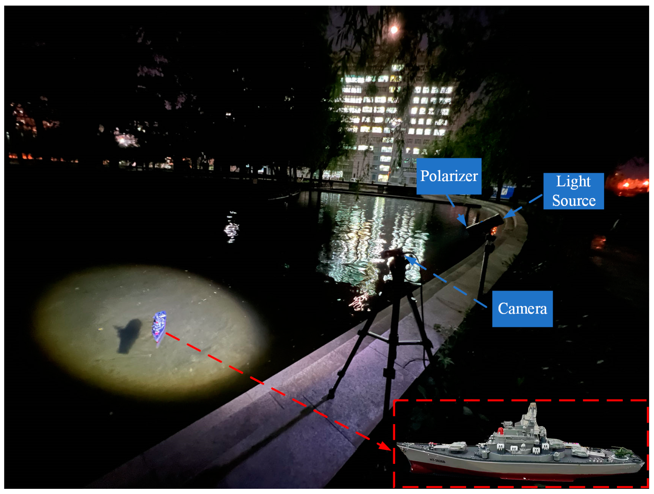
In addition to stationary target detection, there is also a requirement for moving target detection in real life. Based on this, we carry out indoor and outdoor simulation experiments. The size of the glass water tank used in the indoor simulation experiment is 80 × 40 × 45 cm, and the moving target used is a commercially available submarine model with dimensions of 15 × 5.8 × 4.5 cm, and a dive speed of 5 cm/s in the water. As shown in Figure 7a,b, the submarine model dives at a uniform speed during the indoor simulation experiment. The polarization reflection suppression system was placed in a position where it could directly observe the submarine model’s complete dive process. In the outdoor simulation experiment, the outdoor pool was selected as the test site, as shown in Figure 8. The wind speed is 3 m/s and the temperature is 13 °C. The DoFP polarization camera is used to acquire continuous multi-frame images of the remote-control ship moving at 6 km/h in the water. It is worth noting that there are some leafy floating objects on the water surface, which are regarded as interference objects during target detection.

4.2. Moving Target Detection Algorithm

Moving target detection is the process of obtaining relative spatial position changes by eliminating redundant information in time and space in sequence images using machine vision methods. The current moving target detection algorithms are mainly categorized into background difference method [23], inter-frame difference method [24], and optical flow method [25,26]. The Gaussian mixture model algorithm derived from the background difference method in recent years can extract detailed features such as target shape by iterating frame by frame. However, this algorithm is easily affected by the ambient light to misjudge the projection of the moving target, which leads to trailing in the results [27]. The inter-frame difference method differentiates two or three continuous frames to obtain the shape of the moving target. The algorithm has low complexity and is insensitive to illumination changes, but when the target appears to have a large uniform gray scale, the detection results are prone to appear as voids inside the target. Optical flow methods are categorized into dense and sparse optical flow methods based on the sparsity of the two-dimensional vectors of the optical flow field. Although the sparse optical flow method is less computationally intensive, it has lower computational accuracy than the dense optical flow method.
When moving target detection is performed under strong reflected light interference, a large number of non-target moving pixel points are misjudged as target moving pixel points due to background noise interference, which results in false detection in the detection results. At the same time, some areas of pixels are saturated during imaging, and some areas are obscured by light spots when the target is moving. This leads to missed detections in the detection results. Since different moving target detection algorithms have their limitations, we combine the Gaussian mixture modeling algorithm and inter-frame differencing method with the dense optical flow method for moving target detection. The background interference information is removed and then the relative position change of the target is judged. The advantages of the algorithm are utilized and its limitations are avoided. The most suitable moving target detection algorithm under strongly reflected light interference is finally obtained, which provides more technical references for target detection under strong reflected light interference.
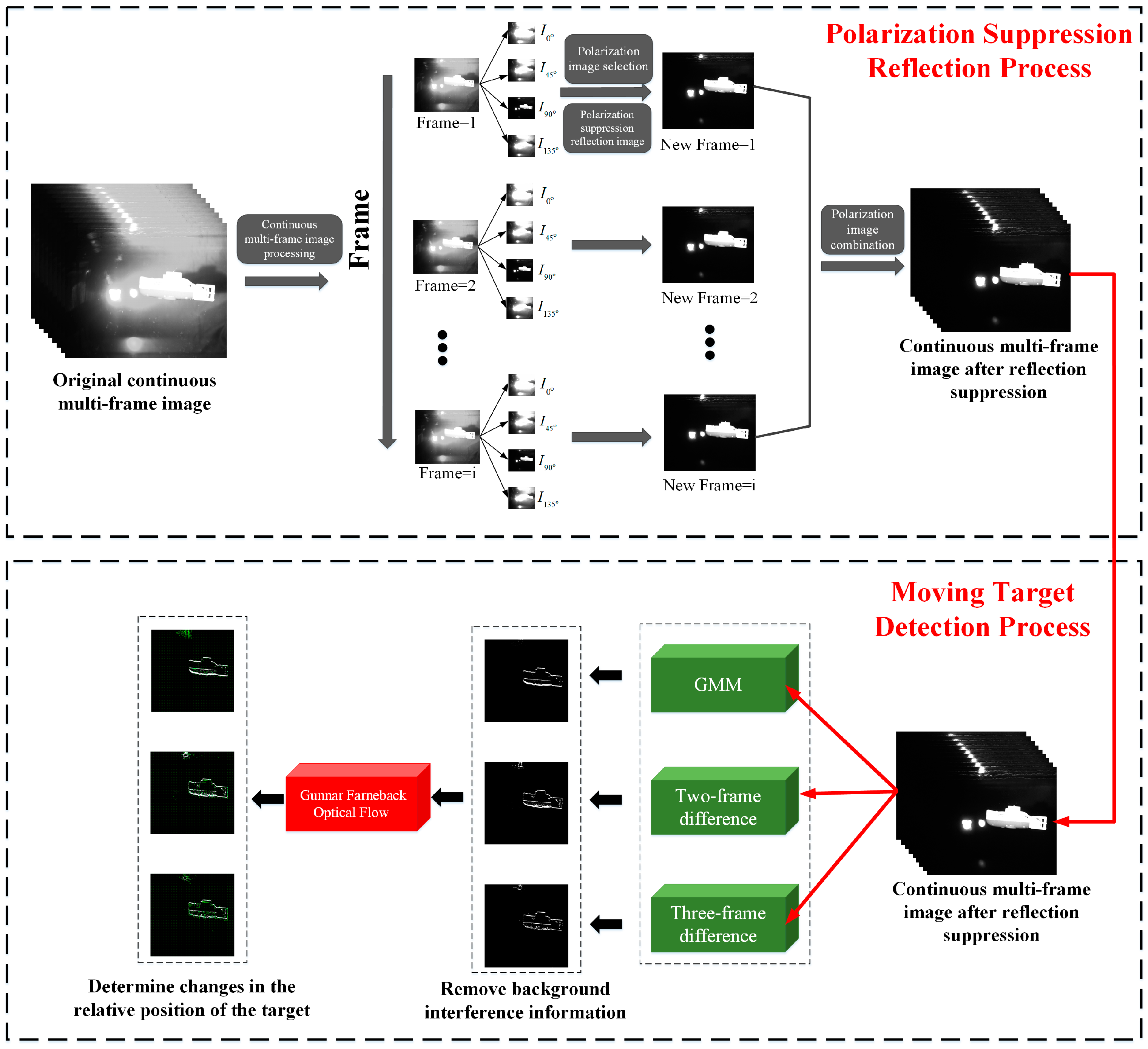
Moving target detection algorithms require a certain number of images for modeling computations. In moving target detection, we first recombine the continuous multi-frame images obtained under different illumination conditions into five different sets of continuous multi-frame images according to the five methods described in Section 3.2. Secondly, the reorganized continuous multi-frame images are passed through the two-frame difference (TWOFD) method, three-frame difference (THREEFD) method, and Gaussian mixture model (GMM) algorithm to remove the background interference information to reduce the subsequent computational complexity. Finally, the computed images are combined with the Gunnar Farneback (GF) dense optical flow algorithm to determine the target’s relative position change [28]. In the calOpticalFlowback function, the scale parameter pyr_scale is set to 0.5, the number of pyramid layer levels is 3, the number of iterations per pyramid layer iterations is 3, the pixel domain range size poly_n is 5, the Gaussian standard deviation poly_sigma is 1.2, and the optical flow block interval is 10. It needs to be particularly noted that the GF optical flow algorithm is characterized by traversing the pixel points in the image that undergo relative position changes according to the set optical flow block interval and the direction of the pixel point movement is marked by arrows. The researcher can analyze the motion pattern of the target through the labeled directions and the length of the arrows in the figure. The schematic diagram of the complete moving target detection process is shown in Figure 9.

4.3. Experiments and Analysis of Results

4.3.1. Experimental Analysis of Polarization Reflection Suppression

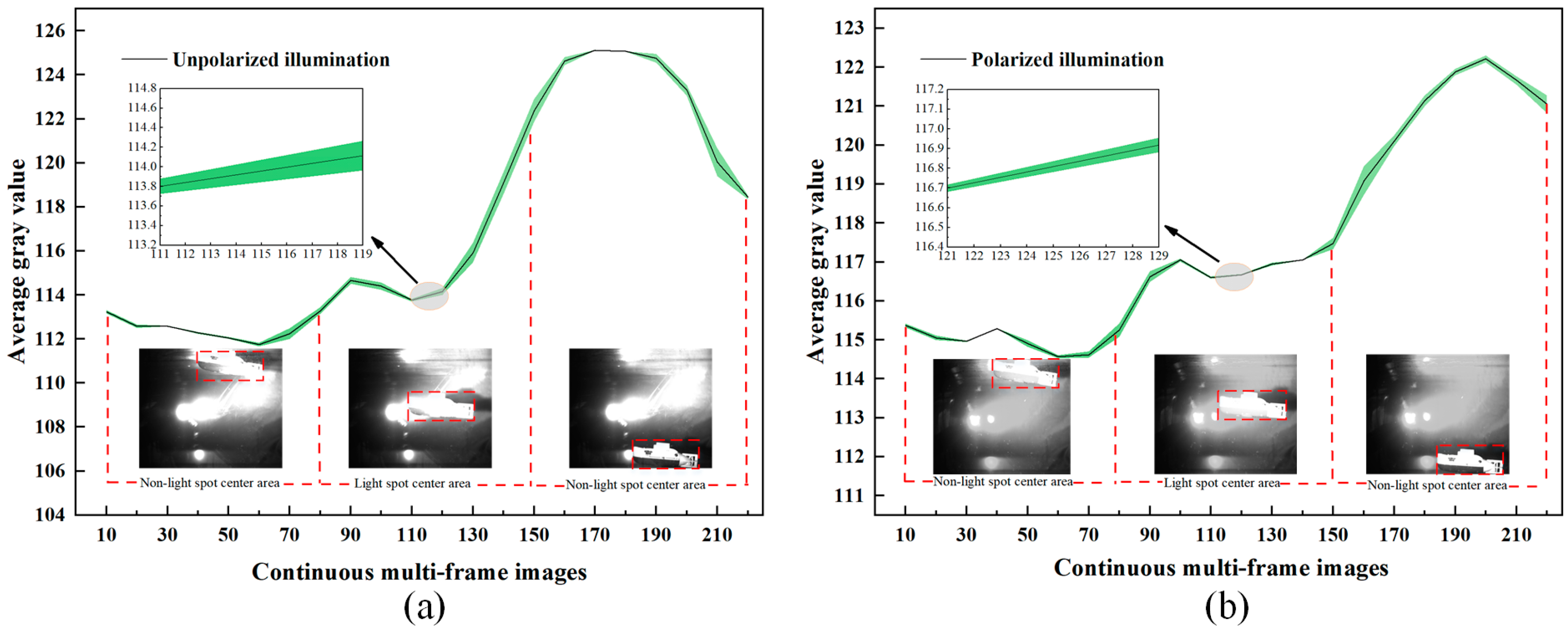
The polarization modulation strategy of the light source and detector used in this paper in a bidirectional manner is a low-cost and efficient acquisition method, which provides more possibilities for real-time motion detection of targets. In the specific comparison experiments due to the need for polarization modulation of the light source, it is necessary to carry out two groups of target motion direction and speed, almost the same as control group experiments. Since indoor simulation experiments do not need to consider the influence of wind direction, water flow, and other environmental factors, the results of indoor experiments are used as the main analysis samples in this paper. In this paper, two sets of continuous multi-frame images with unpolarized illumination and polarized illumination are acquired, in order to represent the motion process of the target moving from the non-light spot center area to the light spot center area and then out of the light spot center area. Combined with the moving target’s motion speed selected in this paper, continuous multi-frame images comprising an effective total of 210 frames were acquired. Among them, images from frames 10 to 80 correspond to the target position in the non-light spot center area, images from frames 81 to 150 correspond to the target position in the light spot center area, and images from frames 151 to 220 correspond to the target position in the non-light spot center area. The average gray values of the two sets of continuous multi-frame images are shown in Figure 10.
At the light spot center region, nine continuous frame images are selected from the continuous multi-frame images, which are analyzed by three image evaluation indexes, namely, image average gray value, standard deviation, and contrast between the target and the background, as shown in Figure 11. Meanwhile, to visualize the comparison of moving target images obtained by different imaging methods, we intercepted the first frame among the continuous nine-frame images for the comparison of detailed features, as shown in Figure 12.
From Figure 11 and Figure 12, it is apparent that the average gray value of method 5 is 30.71. Method 5 has the smallest light spots in the image compared to the other four methods, and there is a significant reduction in the brightness of the image. The standard deviation mean value of the method 5 images is 62.56, and the difference between the target and background gray value is more significant. It is shown in the image that the target is brighter and the background is darker. The contrast mean value of the method 5 images is 0.78, which is a significant improvement in the recognition of target detail features compared to other methods. In summary, method 5 is generally higher than the other methods in different image evaluation metrics. Target saliency in the method 5 image is relatively highest, and the background specular reflection has relatively minimal effect on the target.
To demonstrate the superiority of the orthogonal polarization imaging reflection suppression method, the experiments were conducted outdoors as an auxiliary analysis in this paper. The detailed features of the target obtained under different methods are shown in Figure 13.
The reflected light formed by the active illumination light shining on the floating objects on the water surface is a common noise source in outdoor simulation experiments. If the interference of the noise signal on the target is not considered during target imaging, the probability of missed and false detection will be increased in the subsequent moving target detection. It can be seen in Figure 13 that more noise appears around the target in the images obtained by methods 1–4, which easily interferes with the detection of the target. In comparison with the other four methods, the target saliency in the image obtained by method 5 is higher, and most of the noise signals formed by the floating objects on the water surface are successfully removed. At the same time, the target light intensity value did not become lower due to the suppression of the noise signal, the contrast between the target and the background was relatively high, and it was easier to obtain detailed information about the target. In addition, due to the relatively small amount of noise in the image, the accuracy of target recognition will also be improved in the subsequent moving target detection, and the problems of missed and false detections during detection will be reduced.

4.3.2. Moving Target Detection Experiment

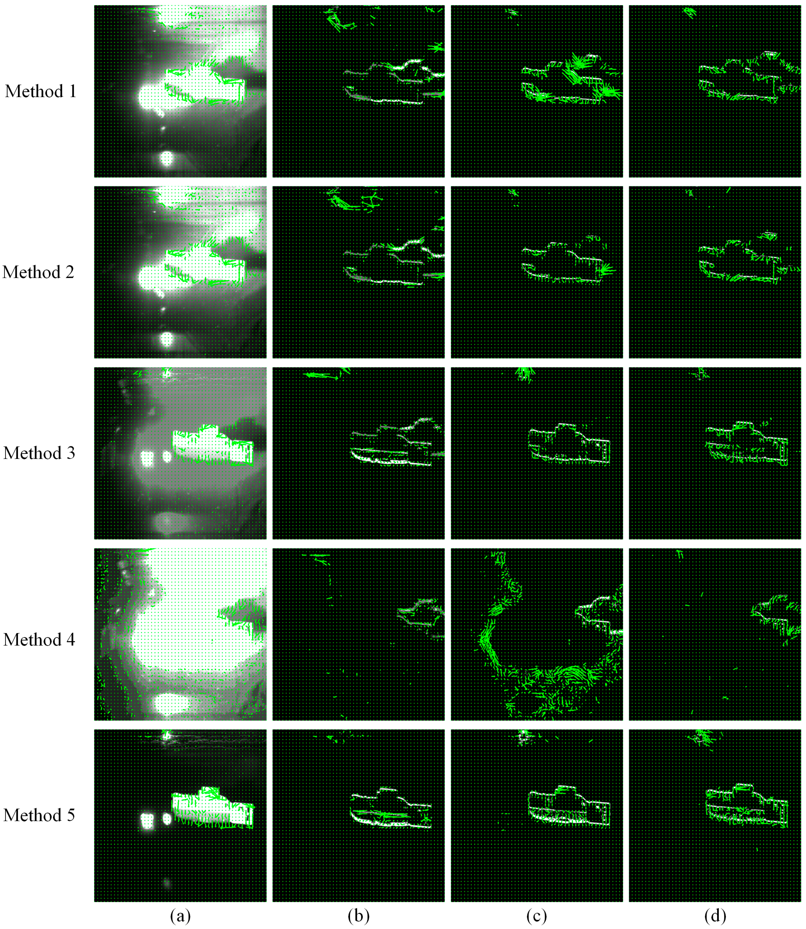
According to the steps shown in Figure 9, the moving target detection process is divided into two steps, which are removing background interference information and determining changes in the relative position of the target. We remove the background interference information using GMM, TWOFD, and THREEFD algorithms from continuous multi-frame images after reflection suppression and extract the effective target information in the images. The resulting images obtained by removing the background interference information are then passed through the GF dense optical flow algorithm to determine changes in the relative position of the target. The results of moving target detection are shown in Figure 14.
In the comparison of methods for removing background interference information, as shown in Figure 14b–d, methods 1 to 4 detect both the body and the shadow of the target. This increases unnecessary computation in moving target detection, while the shadow of the target tends to interfere with the detection of the target and reduces the accuracy of the detection results. The results of moving target detection by method 5 highlight the edge contour of the target well, with the number of shadow pixels at almost zero, better retaining the target’s feature information. When the background specular reflected light is not effectively suppressed, target detection using the GMM, TWOFD, and THREEFD algorithms will produce a large amount of missed and false detections in the results. This is because these algorithms misjudge the background and the target during computation, which leads to biased detection results. After combining these algorithms with the orthogonal polarization imaging reflection suppression method, the misjudged non-target moving pixel points are significantly reduced and the accuracy is improved in the detection results. This provides more accurate reference information for the subsequent determination of changes in the relative position of the target.
In the comparison of determining the accuracy of the target’s relative position change, the image without pre-removed background interference information is calculated by the dense optical flow algorithm, which appears to have a large number of pixel points that are not the target’s relative motion position change, as shown in Figure 14a. This is because the dense optical flow algorithm misidentifies both the background pixels and the target shadow pixels of the illumination change as target pixels, which can easily cause the researcher to misjudge the target’s relative motion position change. From Figure 14b–d, it can be seen that the image with pre-removed background interference information removes most of the background interference objects, and more accurately determines the pixel points of the target’s relative motion position change after being calculated by the dense optical flow algorithm. This can help researchers analyze the target motion pattern more accurately. In addition, the detection results of the GMM-GF, TWOFD-GF, and THREEFD-GF algorithms, which are commonly used in current research, are demonstrated in method 1 in a strongly reflected light interference scenario. It can be seen that the above algorithms have detected the pixel points in the image that have undergone a relative position change, but the target’s shadow pixel points are also detected at the same time. The direction of the target’s relative position change is downward while some of the target’s shadow pixels change in a random direction. This can interfere with the determination of the relative position change of the target. If the number of such pixels increases, it may affect the consistency of the target’s relative position change and subsequent analysis of the target’s motion pattern. Method 5 shows the detection results of the GMM-GF, TWOFD-GF, and THREEFD-GF algorithms after utilizing the orthogonal polarization imaging reflection suppression method. It can be seen that the three algorithms accurately label the pixel points in the image where the relative position change occurs. The target’s relative position change has a good consistency and the overall target motion direction is downward. The conclusion aligns with the downward motion direction of the moving target observed during the experiments.
In order to verify the effectiveness of the polarization suppressed reflection method combined with the moving target detection algorithm, we use Accuracy, Precision, and Recall for the image metrics evaluation [29]. The calculation equation is the following:
A c c u r a c y = ( T P + T N ) / ( T P + T N + F P + F N ) P r e c i s i o n = T P / ( T P + F P ) R e c a l l = T P / ( T P + F N )
where TP was retrieved as a positive sample and was indeed a positive sample, TN was not retrieved as a positive sample and was indeed a negative sample, FP was retrieved as a positive sample but was actually a negative sample, and FN was not retrieved as a positive sample but was actually a positive sample.
The results of image evaluation metrics TP, TN, FP, and FN are shown in Figure 15. The results of the image metrics of Accuracy, Precision, and Recall obtained by further calculations are shown in Figure 16.
By calculating the metrics in Figure 16, the following results are obtained in this paper: (a) We use the GF, GMM-GF, TWOFD-GF, and THREEFD-GF algorithms as the horizontal comparison methods. Comparing the Accuracy metrics, method 5 increases by 15.3% on average compared to methods 1, 2, 3, and 4. Comparing the Precision metric, method 5 increases by 182.78% on average. Comparing the Recall metric, method 5 increases by 174.1% on average. (b) We use method 5 as a vertical comparison method. Comparing the Accuracy metric, the THREEFD-GF algorithm increases by 1.8% on average compared to the GF, GMM-GF, and TWOFD-GF algorithms. Comparing the Precision metric, the THREEFD-GF algorithm increases by 20.3% on average. Comparing the Recall metric, the THREEFD-GF algorithm increases by 10.6% on average. From the above results, it can be seen that the THREEFD-GF algorithm has an obvious advantage over the other three algorithms in the strongly reflected light interference scene. This is because the three-frame differencing method has a strong ability to suppress the background interference noise and is insensitive to light and dark changes of light, which is more suitable to be combined with the dense optical flow algorithm for detecting the target motion. The THREEFD-GF algorithm can effectively avoid detecting the non-target motion pixels when determining the pixels with relative position change, which can help to improve the accuracy of detection. However, for those target shadow pixels that follow the target changes, the THREEFD-GF algorithm also regards them as target pixel points that have undergone relative position changes in their calculations. This will lead to false detection in the detection results. As can be seen from the metrics in Figure 16, the THREEFD-GF algorithm shows significant improvements in the image metrics of Accuracy, Precision, and Recall when the reflection suppression method of orthogonal polarization imaging is used, and when the corresponding values of the image metrics reach the relative highest values. This is represented in the image by (a) effectively reducing the number of detected non-target moving pixels, (b) accurately labeling the pixel points with relative position changes in the image, and (c) better consistency of the target’s relative position changes.
In summary, the THREEFD-GF algorithm is more suitable for moving target detection in scenes with strong reflected light interference. We apply the reflection suppression method of orthogonal polarization imaging to moving target detection, which further improves the Accuracy and other related indexes in the detection results of the THREEFD-GF algorithm, and reduces the missed and false detection problems during detection. When capturing the feature information of a moving target under an active light illumination scenario, an active polarized light source can be preferred for illumination, and the reflection suppression method of orthogonal polarization imaging combined with the THREEFD-GF algorithm can be used to detect the moving target.

5. Discussion

When using active illumination on a smooth background surface, the background specular reflection creates a strong reflection interference light, which tends to cause saturation of large pixel areas in the image. The target reflected light signal is mixed with the background specular reflected light signal, which makes it difficult to distinguish the target from the background. The traditional reflection suppression methods avoid reflective areas by constantly adjusting the detection angle of the detector or by simply removing the reflective areas from the image. This seriously limits the maneuverability in practice and poses a significant challenge for some scientific studies. The common imaging strategy is to add a polarizer in front of the detector to reduce the amount of light entering the detector. Although the single polarizer reflection suppression method reduces the amount of light entering the detector, the target details are still not easily discernible when the background reflected light remains strong; thus, it may increase the probability of missed and false detection in moving target detection. Some researchers proposed the method of reducing the image brightness by time-domain fusion [13], but this method cannot meet the real-time requirements of suppressing reflection. When there is a change in the relative position of the target, the target and background may be misjudged during detection, which may result in the loss of target information.
We derive from Mueller matrix polarization decomposition that the background specular reflected light and the target reflected light have obvious differences in depolarization characteristics. Based on this, we propose a reflection suppression method based on orthogonal polarization imaging. The method employs a polarization modulation strategy in a bidirectional manner between the light source and the detector. First, the polarization information difference is amplified by active polarized illumination between the background specular reflected light and the target reflected light. Then, the method suppresses the background specular reflected light to realize the recovery of the target. Our study aims to ensure that the detailed features of the target are clear during the imaging process under the relatively strong reflected light of the target, and not to cause loss of image information due to the excessive intensity of the light source. The experimental results show that by using the orthogonal polarization imaging reflection suppression method, the average gray value of the image obtained is 30.71, the mean value of the image standard deviation is 62.56, and the mean value of the image contrast is 0.78. It is shown in the image that the target is brighter and the background is darker, and the recognition of the detailed features of the target has significantly improved. The orthogonal polarization imaging reflection suppression method effectively reduces the interference of background specular reflection on the target image compared with other polarization reflection suppression methods.
We apply the orthogonal polarization imaging reflection suppression method to moving target detection and compare different moving target detection algorithms in a strong reflected light interference scene. The experimental results show that THREEFD is more suitable to be combined with the dense optical flow algorithm to detect the target pixels that undergo relative position changes in a strong reflected light interference scene compared to other moving target detection methods. It has obvious advantages in the metrics of Accuracy, Precision, and Recall. After combining the polarization reflection suppression method, the indices such as Accuracy can be further improved. Applying the orthogonal polarization imaging reflection suppression method to target detection will help to improve the active illumination detection effect. The method in this paper is expected to provide more powerful technical support for target detection in more active light illumination scenarios.

6. Conclusions

To address the problem of strongly reflected interfering light generated by active illumination light through specular reflection, we derive from Mueller matrix polarization decomposition that the background specular reflected light and the target reflected light have obvious differences in depolarization characteristics. In this paper, an orthogonal polarization imaging method is proposed to suppress the reflection. The method adopts a polarization modulation strategy in a bidirectional manner between the light source and the detector, which can effectively suppress the background specular reflection light and improve the recognition of target detail information at the same time. In the experiment, the polarization reflection suppression method is applied to the moving target detection, and the different moving target detection algorithms are compared in the scene of strongly reflected light interference. The results show that the three-frame difference method is more suitable to be combined with the dense optical flow algorithm to detect the target pixel points that undergo relative position changes in a strongly reflected light interference scene. The detection results have obvious advantages in Accuracy, Precision, and Recall. After combining the polarization reflection suppression method, the indices such as Accuracy can be further improved, effectively reducing the missed and false detection problems during detection. For part of the light spots appearing in the image, although it does not affect the moving target detection, the light spots will increase the computational amount of the subsequent moving target detection algorithm. The next step of the work focuses on trying to optimize the processing of image bright spots that cannot be suppressed using image fusion methods to achieve the best suppression effect.

Author Contributions

Conceptualization, J.W. and J.D.; methodology, J.W.; software, S.M. and R.F.; validation, J.W. and G.X.; formal analysis, S.M.; investigation, R.F.; resources, J.W.; data curation, G.X.; writing—original draft preparation, J.W.; writing—review and editing, J.D. and Q.F.; visualization, S.M.; supervision, R.F.; project administration, J.D.; funding acquisition, J.D. All authors have read and agreed to the published version of the manuscript.

Funding

This research was funded by the National Natural Science Foundation of Chongqing (cstc2021jcyj-msxmX0145); the Project of Industrial Technology Research and Development in Jilin Province (2023C031-3); and the National Natural Science Foundation of China (62127813).

Data Availability Statement

Data are contained within the article.

Acknowledgments

The authors express their appreciation for the financial support of the National Natural Science Foundation of Chongqing (cstc2021jcyj-msxmX0145), the Project of Industrial Technology Research and Development in Jilin Province (2023C031-3), and the National Natural Science Foundation of China (62127813). We are very grateful to the editors and reviewers for their efficient work.

Conflicts of Interest

The authors declare no conflicts of interest.

References

  1. Zhang, Y.; Fu, Q.; Luo, K.; Yang, W.; Zhan, J.; Zhang, S.; Shi, H.; Li, Y.; Yu, H. Analysis of Two-Color Infrared Polarization Imaging Characteristics for Target Detection and Recognition. Photonics 2023, 10, 1181. [Google Scholar] [CrossRef]
  2. Guan, J.; Cheng, Y.; Chang, G. Time-domain polarization difference imaging of objects in turbid water. Opt. Commun. 2017, 391, 82–87. [Google Scholar] [CrossRef]
  3. Zhu, Z.; Li, X.; Zhang, J.; Zhou, Y.; Zhao, Y. Specular flare suppression method for reflective materials based on the optimal polarizing angle. Appl. Opt. 2022, 61, 8034–8041. [Google Scholar] [CrossRef] [PubMed]
  4. Liang, J.; Wang, X.; He, S.; Jin, W. Sea Surface Clutter Suppression Method Based on Time-domain Polarization Characteristics of Sun Glint. Opt. Express 2019, 27, 2142–2158. [Google Scholar] [CrossRef] [PubMed]
  5. Zhan, Y.; Hu, D.; Liu, K. Adaptive Structured Light for High-Reflective Areas. Acta Opt. Sin. 2022, 42, 115–123. [Google Scholar]
  6. Deng, J.; Zhu, J.; Li, H.; Liu, X.; Guo, F.; Zhang, X.; Hou, X. Underwater dynamic polarization imaging without dependence on the background region. Opt. Express 2024, 32, 5397–5409. [Google Scholar] [CrossRef] [PubMed]
  7. Yang, L.; Liang, J.; Zhang, W.; Ju, H.; Ren, L.; Shao, X. Underwater polarimetric imaging for visibility enhancement utilizing active unpolarized illumination. Opt. Commun. 2019, 438, 96–101. [Google Scholar] [CrossRef]
  8. Zhang, Y.; Shi, Z.; Qiu, T. Infrared small target detection method based on decomposition of polarization information. J. Electron. Imaging 2017, 26, 033004. [Google Scholar] [CrossRef]
  9. Zhang, J.; Zhang, Y.; Shi, Z.; Li, B.; Zhang, Y.; Ling, F.; Zhang, Y.; Liu, D. Suppression Technology for Saturated Water Surface Glint Based on Polarization Characteristics. Acta Opt. Sin. 2022, 42, 81–90. [Google Scholar]
  10. Li, S.; Jiao, J.; Wang, C. Specular Reflection Removal Method Based on Polarization Spectrum Fusion and Its Application in Vegetation Health Monitoring. Spectrosc. Spect. Anal. 2023, 43, 3607–3614. [Google Scholar]
  11. Yang, M.; Xu, W.; Tian, Y.; Sun, Z.; Sun, X. Time-Sharing Infrared Polarization Imaging System for Moving Target Detection. Acta Opt. Sin. 2020, 40, 70–77. [Google Scholar]
  12. Zhu, H.; Qu, H. Adaptive Suppression System of Sea Background Flare. Acta Opt. Sin. 2022, 42, 110–118. [Google Scholar]
  13. Ye, S.; Qu, W.; Li, S.; Wang, J. Sea Surface Glint-Suppression Method Based on the Polarization Time-Domain Characteristics. Acta Opt. Sin. 2021, 41, 26–32. [Google Scholar]
  14. Ren, K.; Lv, Y.; Gu, G.; Chen, Q. Calculation method of multiangle polarization measurement for oil spill detection. Appl. Opt. 2019, 58, 3317–3324. [Google Scholar] [CrossRef] [PubMed]
  15. Zhao, H.; Ji, Z.; Zhang, Y.; Sun, X.; Song, P.; Li, Y. Mid-infrared imaging system based on polarizers for detecting marine targets covered in sun glint. Opt. Express 2016, 24, 16396–16409. [Google Scholar] [CrossRef] [PubMed]
  16. Soni, J.; Purwar, H.; Ghosh, N. Quantitative polarimetry of plasmon resonant spheroidal metal nanoparticles: A Mueller matrix decomposition study. Opt. Commun. 2012, 285, 1599–1607. [Google Scholar] [CrossRef]
  17. Lu, S.; Chipman, R. Interpretation of Mueller matrices based on polar decomposition. J. Opt. Soc. Am. A 1996, 13, 1106–1113. [Google Scholar] [CrossRef]
  18. Swami, M.; Manhas, S.; Buddhiwant, P.; Ghosh, N.; Uppal, A.; Gupta, P. Polar decomposition of 3 × 3 Mueller matrix: A tool for quantitative tissue polarimetry. Opt. Express 2006, 14, 9324–9337. [Google Scholar] [CrossRef] [PubMed]
  19. Liu, F.; Zhang, S.; Han, P.; Chen, F.; Zhao, L.; Fan, Y.; Shao, X. Depolarization index from Mueller matrix descatters imaging in turbid water. Chin. Opt. Lett. 2022, 20, 022601. [Google Scholar] [CrossRef]
  20. Feng, F.; Wu, G.; Wu, Y.; Miao, Y.; Liu, B. Algorithm for Underwater Polarization Imaging Based on Global Estimation. Acta Opt. Sin. 2020, 40, 75–83. [Google Scholar]
  21. Xu, J.; Zhao, J.; Li, X.; Liu, H.; Liu, T.; Zhai, J.; Hu, H. Polarization Imaging in Turbid Water Based on Spectral Information. Acta Opt. Sin. 2023, 43, 269–277. [Google Scholar]
  22. Wang, J.; Duan, J.; Fu, Q.; Xie, G.; Mo, S.; Fang, R. Polarization Suppression Reflection Method Based on Mueller Matrix. Acta Opt. Sin. 2023, 43, 162–174. [Google Scholar]
  23. Cucchiara, R.; Piccardi, M.; Prati, A. Detecting moving objects, ghosts, and shadows in video streams. IEEE T. Pattern Anal. 2003, 25, 12–15. [Google Scholar] [CrossRef]
  24. Tsai, D.; Lai, S. Independent component analysis-based background subtraction for indoor surveillance. IEEE T. Image Process. 2009, 18, 158–167. [Google Scholar] [CrossRef] [PubMed]
  25. Lv, J.; Ji, H.; Jiang, Y.; Wang, B. A New Flow Pattern Identification Method for Gas-Liquid Two-Phase Flow in Small Channel Based on an Improved Optical Flow Algorithm. IEEE Sens. J. 2024, 23, 27634–27644. [Google Scholar] [CrossRef]
  26. Wang, Y.; Li, Y.; Lv, H. An optical flow estimation method based on multiscale anisotropic convolution. APPL. INTELL. 2024, 54, 398–413. [Google Scholar] [CrossRef]
  27. Wang, C.; Wang, T.; Wang, E.; Sun, E.; Luo, Z. Flying Small Target Detection for Anti-UAV Based on a Gaussian Mixture Model in a Compressive Sensing Domain. Sensors 2019, 19, 2168. [Google Scholar] [CrossRef]
  28. Farneback, G. Two-Frame Motion Estimation Based on Polynomial Expansion. In Proceedings of the Image Analysis: 13th Scandinavian Conference, Halmstad, Sweden, 29 June–2 July 2003. [Google Scholar]
  29. Kwan, C.; Larkin, J. Detection of Small Moving Objects in Long Range Infrared Videos from a Change Detection Perspective. Photonics 2021, 8, 394. [Google Scholar] [CrossRef]
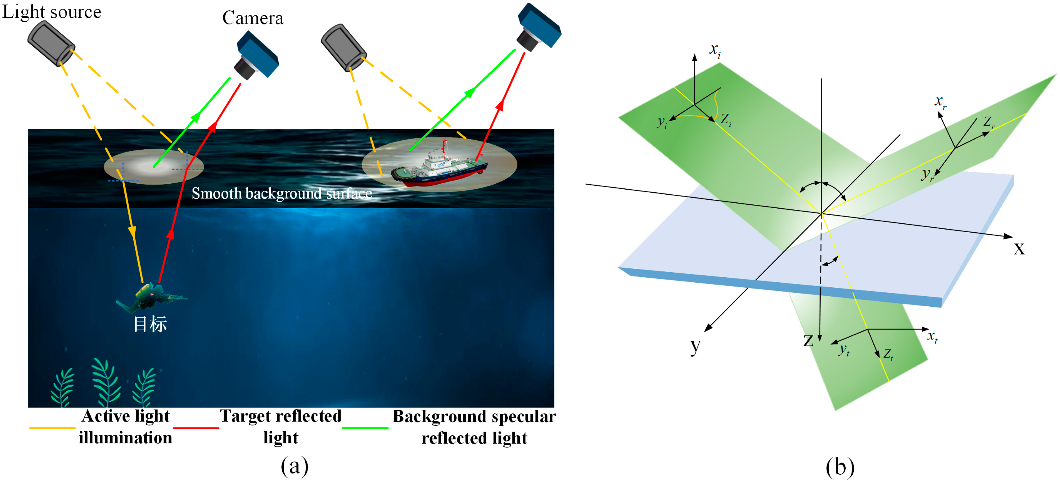
Figure 1. Spatial planes formed by incident, reflected, and refracted light: (a) schematic diagram of active lighting detection; (b) schematic diagram of incident light being reflected and refracted.
Photonics 11 00445 g001
Figure 2. Simulation relationship curves for different refractive index media: (a) reflectivity of S-polarized component; (b) reflectivity of P-polarized component; (c) refractivity of S-polarized component; (d) refractivity of P-polarized component; (e) degree of polarization of reflected light; (f) degree of polarization of refracted light.
Photonics 11 00445 g002
Figure 3. Mueller matrix images of different targets: (a) tennis ball and grass; (b) metal material.
Photonics 11 00445 g003
Figure 4. Depolarized images of different targets: (a) tennis ball and grass; (b) metal material.
Photonics 11 00445 g004
Figure 5. Plot of depolarization intensity values: (a) plot of depolarization intensity values of tennis balls and grass; (b) plot of depolarization intensity values of metal materials.
Photonics 11 00445 g005
Figure 6. Image detail features under different imaging methods.
Photonics 11 00445 g006
Figure 7. Indoor simulation experiment: (a) schematic diagram of the experimental device; (b) physical diagram of the experimental device.
Photonics 11 00445 g007
Figure 8. Outdoor simulation experiment.
Photonics 11 00445 g008
Figure 9. Schematic diagram of the process of detecting a moving target using the polarization suppressed reflection method.
Photonics 11 00445 g009
Figure 10. Average gray values of continuous frame images under different illumination conditions: (a) unpolarized illumination; (b) polarized illumination.
Photonics 11 00445 g010
Figure 11. Image evaluation metrics corresponding to different methods: (a) average gray value and standard deviation for method 1 images; (b) average gray value and standard deviation for method 2 images; (c) average gray value and standard deviation for method 3 images; (d) average gray value and standard deviation for method 4 images; (e) average gray value and standard deviation for method 5 images; (f) contrast between target and background corresponding to different method images.
Photonics 11 00445 g011
Figure 12. Target detail features under different imaging methods during indoor experiments: (a) method 1; (b) method 2; (c) method 3; (d) method 4; (e) method 5.
Photonics 11 00445 g012
Figure 13. Target detail features under different imaging methods during outdoor experiments: (a) method 1; (b) method 2; (c) method 3; (d) method 4; (e) method 5.
Photonics 11 00445 g013
Figure 14. Moving target detection results: (a) GF; (b) GMM-GF; (c) TWOFD-GF; (d) THREEFD-GF.
Photonics 11 00445 g014
Figure 15. Results of image metrics for TP, TN, FP, and FN: (a) TP; (b) TN; (c) FP; (d) FN.
Photonics 11 00445 g015
Figure 16. Results of image evaluation metrics for Accuracy, Precision, and Recall: (a) Accuracy; (b) Precision; (c) Recall.
Photonics 11 00445 g016
Disclaimer/Publisher’s Note: The statements, opinions and data contained in all publications are solely those of the individual author(s) and contributor(s) and not of MDPI and/or the editor(s). MDPI and/or the editor(s) disclaim responsibility for any injury to people or property resulting from any ideas, methods, instructions or products referred to in the content.