Article

Research on Dual-Grating Spacing Calibration Method Based on Multiple Improved Complete Ensemble Empirical Mode Decomposition with Adaptive Noise Combined with Hilbert Transform

1
College of Metrology & Measurement Engineering, China Jiliang University, Hangzhou 310018, China
2
Shanghai Institute of Measurement and Testing Technology, Shanghai 201203, China
3
Shanghai Key Laboratory of Online Test and Control Technology, Shanghai 201203, China
*
Author to whom correspondence should be addressed.
Photonics 2024, 11(5), 443; https://doi.org/10.3390/photonics11050443
Submission received: 18 April 2024 / Revised: 4 May 2024 / Accepted: 8 May 2024 / Published: 10 May 2024
(This article belongs to the Special Issue Novel Ultraviolet Laser: Generation, Properties and Applications)

Abstract

:
The paper proposes a method for the calibration of spacing in dual-grating based on Multiple Improved Complete Ensemble Empirical Mode Decomposition with Adaptive Noise (ICEEMDAN) combined with Hilbert Transform (HT), referred to as Multiple ICEEMDAN-HT. This method addresses the potential impact of nonlinear factors on phase extraction accuracy, consequently on ranging precision in the homodyne interference of the dual-grating. Building upon the ICEEMDAN algorithm, the signal undergoes iterative decomposition and reconstruction using the sample entropy criterion. The intrinsic mode functions (IMFs) obtained from multiple iterations are then reconstructed to obtain the complete signal. Through a simulation and comparison with other signal decomposition methods, the repeatability and completeness of signal reconstruction by Multiple ICEEMDAN are verified. Finally, an actual dual-grating ranging system is utilized to calibrate the spacing of the planar grating. Experimental results demonstrate that the calibration relative error of the Multiple ICEEMDAN-HT phase unwrapping method can be reduced to as low as 0.07%, effectively enhancing the signal robustness and spacing calibration precision.

1. Introduction

Grating spacing calibration is the pivotal technology for meeting the high-precision positioning demands of nanoscale measurement technology, and has been widely used in micro/nanofabrication, precision manufacturing, microelectronics, and other fields rooted in nanotechnology research [1]. Common methods for grating spacing calibration include long trace profiler (LTP) [2,3,4], scanning reference grating (SRG) [5,6,7], Atomic Force Microscopy (AFM), and grating diffraction [8,9,10]. LTP enables the non-contact full-range spacing measurement of gratings, but is characterized by its high cost and susceptibility to occlusion and eccentricity effects. High-precision reference signals can be provided by SRG, which are utilized for calibration and measurement of other gratings or optical systems. However, SRG systems are typically complex and require precise design and debugging. AFM offers high resolution, multifunctionality, and non-destructive capabilities, but faces challenges such as high costs, slow imaging speeds, and stringent sample requirements. Compared with the above three methods, grating diffraction is more convenient, simpler, and faster. The local measurement is more uniform. However, errors in grating diffraction arise from various factors including light source stability, the quality of grating fabrication, optical path structure, and effects from grating misalignment and circuit errors [11,12].
To enhance the accuracy of grating spacing calibration, a one-dimensional self-traceable Cr nano grating was fabricated by the nano-metrology team led by Academician Li Tongbao at Tongji University [13], which has been approved as a national primary standard substance. The grating spacing is 212.7705 ± 0.0049 nm, serving as a reference with strict accuracy and stability. Therefore, the laser wavelength can be adjusted to improve light source stability and reduce errors caused by uneven grating fabrication. In the actual calibration process, both the optical path structure and grating misalignment can be adjusted through physical methods [14].
The accuracy of the spacing measuring system primarily depends on the extraction of the phase difference in the dual-grating. Ideally, one could obtain complete sinusoidal interference signals with zero DC bias and equal AC amplitudes, which are orthogonal to each other. However, in practical scenarios, factors such as fluctuations in energy due to laser decay over time, internal noise of photoelectric conversion components, and external disturbances caused by power supply to the vibration displacement stage can all manifest as DC drift, amplitude fluctuations, and noise spikes in the interference signals, and then lead to the generation of nonlinear signals. As a result, the accuracy of phase information extraction is diminished, leading to significant errors in grating spacing calibration [15]. Therefore, in order to enhance the precision of grating spacing calibration, suitable signal processing methods are required to extract genuine and precise phase distribution.
Currently, the phase information of grating interference signals can be characterized through both time domain and frequency domain representations [16]. Traditional methods for phase unwrapping in the time/frequency domain include Fourier Transform [17], power spectral density estimation [18], Hilbert Transform [19], and arctangent phase shift [20]. These four methods are typically used for the global analysis of signals and are more suitable for small sets of discrete points and steady signals. However, when dealing with non-stationary and nonlinear signals, they are prone to being affected by noise, leading to phase jump issues, and thus may not provide sufficient phase information [21]. In response to the limitations of traditional algorithm, Professor Norden Huang [22] first proposed Empirical Mode Decomposition (EMD) for time/frequency analysis in 1998. This pioneering work laid the foundation for a series of signal processing techniques. In 2018, Deng Wen et al. [23] combined EMD with Hilbert Transform. By adaptively decomposing signals into several Intrinsic Mode Functions (IMFs) using EMD, they effectively retained the effective components and reconstructed them after applying the Hilbert Transform. This method successfully achieved denoising and phase unwrapping of nonlinear interference signals, thereby mitigating the impact of nonlinearity on phase accuracy. However, IMFs decomposed by EMD exhibit mode mixing, and their ability to filter out noise is limited, thus hindering further signal processing. In 2023, Yang Keyuan et al. [24] proposed a method based on Complementary Ensemble Empirical Mode Decomposition (CEEMD) combined with Hilbert Transform (CEEMD-HT). This innovative approach effectively suppresses mode mixing, enhancing the robustness of signal noise. Despite its advancements, the CEEMD-HT method still faces challenges in fully eliminating mode mixing, leading to noise residue. Additionally, the decomposition efficiency of CEEMD-HT remains a concern, warranting further investigation.
To this end, a high-precision dual-grating spacing calibration method is proposed in this paper, termed Improved Complete Ensemble Empirical Mode Decomposition with Adaptive Noise (ICEEMDAN) combined with Hilbert Transform (ICEEMDAN-HT). Based on Empirical Mode Decomposition, the ICEEMDAN method is further optimized, and the sample entropy threshold component selection mechanism is introduced to perform multiple decomposition and reconstruction of signals. Sample entropy [25] is a widely used entropy feature calculation method, which is used to describe the complexity of time series. The advantages of using sample entropy are as follows: 1. the calculation method does not depend on data length; 2. it has better consistency; 3. it is less affected by signal data loss. Therefore, sample entropy can be employed as a fundamental criterion for characterizing ICEEMDAN components. The IMFs stored after multiple iterations are summed and reconstructed, and then the phase information is extracted by Hilbert Transform. The measurement result of AFM is utilized as the standard, and the calibration results of this method are compared with those of other algorithms to assess its effectiveness and decomposition completeness.

2. Theoretical Analysis

2.1. Principle of Dual-Grating Homodyne Interferometer Calibration

As shown in Figure 1, the homodyne interferometer spacing measurement system of the dual-grating mainly consists of a laser source, dual-grating ranging optical path, signal acquisition, and processing module. The linearly polarized light source is provided by the single frequency laser, which is proportionally split at the polarizing beam splitter (PBS1) after collimation. The beam enters the symmetrically structured dual-grating interference region, where they are then directed into four beams through PBS2 and PBS3. Each beam is incident onto the dual-grating from four non-overlapping, symmetric, parallel optical paths at the Littrow angle [26,27]. The heights of the left and right incident spots are consistent, and their positions along the centerline of the grating are relatively consistent. The standard grating (G1) and the grating to be calibrated (G2) are positioned parallel to each other on the nano-vibration displacement stage. When mechanical vibrations are generated along the grid direction by the displacement stage, diffraction occurs at both dual-gratings, and the −1-order diffracted light returns along the original path. Finally, the interference phenomenon is captured by detectors (PD1, PD2), and the interference signals are transmitted to a computer via a data acquisition card for signal processing. The intensity of the interference signal obtained through the homodyne method can be represented as I 1 , I 2 :
I 1 = A 1 + B 1 cos ( Δ φ 1 )
I 2 = A 2 + B 2 cos ( Δ φ 2 )
where A represents the DC bias (V) and B represents the AC amplitude (V) of the interference signal, while Δ φ denotes the phase difference. Then, the relationship between the displacement difference Δ x due to mechanical vibration and the phase difference Δ φ can be expressed as:
Δ x 1 = Δ φ 1 d 1 4 π
Δ x 2 = Δ φ 2 d 2 4 π
where d 1 represents the standard spacing of the standard grating, and d 2 represents the measured spacing of the grating to be calibrated. Since two gratings move in the same displacement direction, it follows that Δ x 1 = Δ x 2 . By combining Equations (3) and (4), the proportional relationship between the spacing and the phase difference can be obtained as follows:
d 2 = Δ φ 1 d 1 Δ φ 2
d 1 is a constant, and thus, only solving for the phase difference in dual-grating is required. Subsequently, the spacing of the grating to be calibrated can be calculated by Equation (5).
From the above equation, it can be inferred that the accuracy of the spacing measuring system primarily depends on the extraction of the phase difference in dual-grating. During actual measurements, inaccurately installed dual-grating can easily introduce Abbe and cosine errors. In this paper, the grating alignment bracket on the displacement platform is used to adjust the heights at the intersection of the dual-grating using geometric optics methods, ensuring consistency in the alignment of the dual-grating, including pitch and yaw, and parallel alignment of vectors. Subsequently, the displacement platform is driven in the vertical direction of the grating motion, adjusting the grating alignment bracket until the interference signal becomes invisible to the naked eye. This process filters out the effects of Abbe error and cosine errors on the measurement. Therefore, nonlinear errors are the primary factors affecting phase extraction. From the standpoint of signal processing techniques, the collected dual-grating interference signals are calibrated in this article. Through the design and application of specialized calibration algorithms specifically addressing nonlinear errors in grating interference, the precise extraction of phase information from the signals is pursued. The objective is to diminish the influence of nonlinear errors, thereby augmenting the accuracy and stability of the signals.

2.2. The Basic Principle of ICEEMDAN

Empirical Mode Decomposition (EMD) is widely used and considered an effective method for time/frequency analysis. Compared to wavelet threshold decomposition methods, EMD has the advantage of not requiring the selection of basis function. It can adaptively decompose signals based on the distribution of signal extrema, demonstrating strong adaptability and frequency singularity. However, its drawbacks are also evident, as mode mixing is prone to occur during the decomposition process. Specifically, adjacent intrinsic mode components often contain similar characteristic time scales, making it difficult to distinguish overlapping portions of waveforms [22]. In response to this issue, Ensemble Empirical Mode Decomposition (EEMD) was proposed by Wu and Huang et al. [28] in 2009, which adds Gaussian white noise for decomposition and then utilizes ensemble averaging to make components more regular, thereby enhancing the stability and robustness of EMD. However, it also introduces the problems of significant noise residue, resulting in large reconstruction errors. Complementary Ensemble Empirical Mode Decomposition (CEEMD) was proposed by YEH J R et al. [24], which adds complementary white noise to cancel out during ensemble averaging, so as to overcome the low completeness of EEMD. However, CEEMD suffers from slow iteration efficiency, and IMFs are difficult to align in ensemble averaging, affecting the decomposition of different orders.
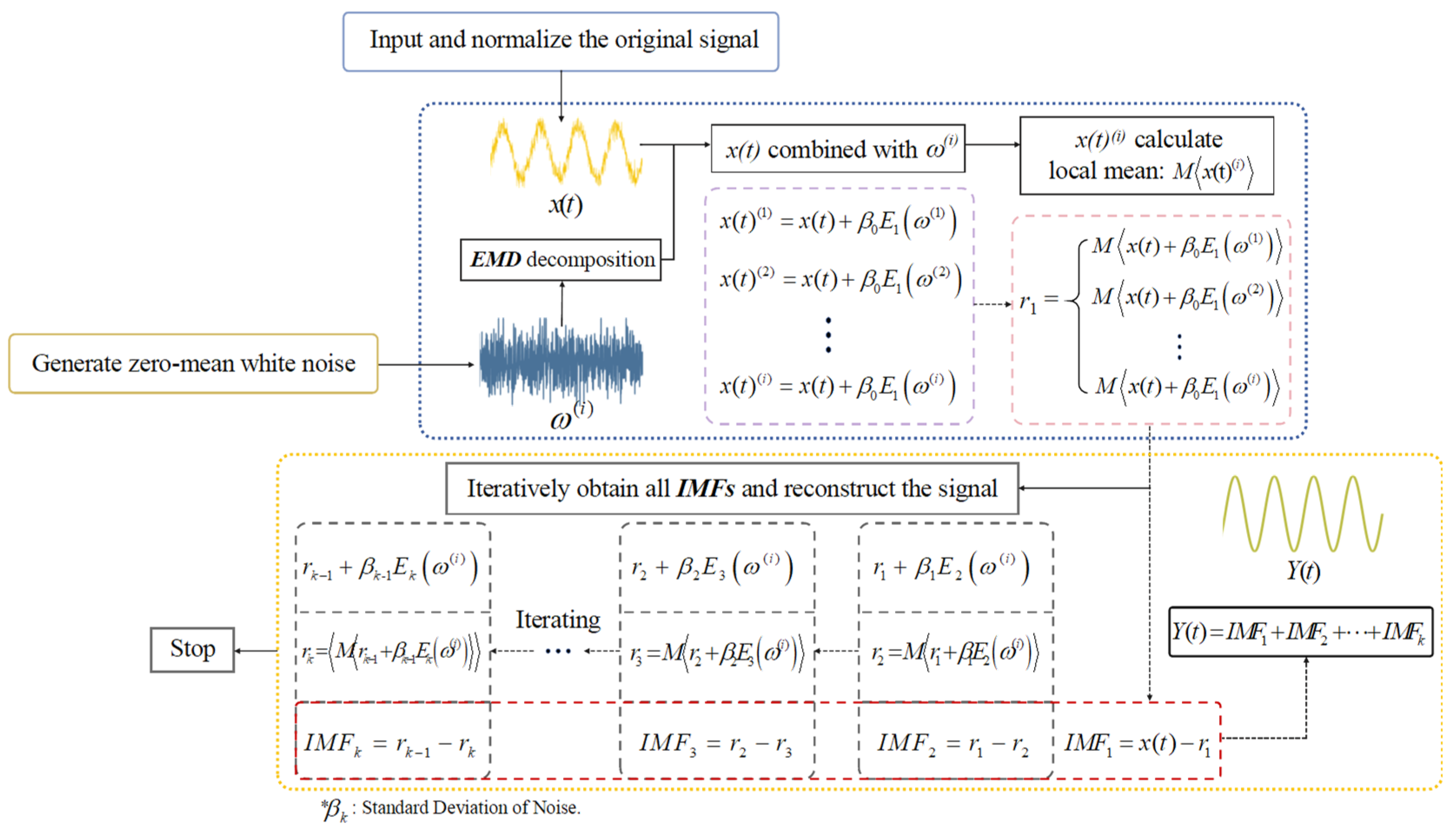
Improved Complete Ensemble Empirical Mode Decomposition with Adaptive Noise (ICEEMDAN) is an improved algorithm proposed to address the shortcomings of the aforementioned methods. By decomposing white noise using EMD and selecting the k th order component to be added to the decomposition process, mode mixing and residual noise are effectively suppressed, and the composition of pseudo-modes is greatly reduced. As shown in Figure 2, the detailed decomposition process of ICEEMDAN is as follows [29]:
  • Firstly, define x ( t ) as the original signal in time series, x ( t ) ( i ) as the signal after adding white noise, M as the local mean of the signal, ω ( i ) as the i th white noise with unit variance and zero mean ( i = 1 , 2 , 3 , , N ), β k represents the standard deviation of the noise, and E k ( ) as the k th IMF component after decomposition by EMD algorithm (where the symbol denotes the average).
  • Secondly, the first Gaussian white noise is decomposed by EMD to construct the signal after adding white noise, which is expressed as x ( t ) ( i ) = x ( t ) + β 0 E 1 ( ω ( i ) ) , where E 1 ( ω ( i ) ) represents the first-order white noise component. The local mean M x ( t ) ( i ) is obtained according to the formula E 1 ( ω ( i ) ) = ω ( i ) M ω ( i ) , and then the first-order residual component r 1 can be calculated by taking the average of M x ( t ) ( i ) :
    r 1 = M x ( t ) ( i )
  • The first-order intrinsic mode component I M F 1 can be obtained by subtracting the original signal x ( t ) from the first-order residual component, which is expressed as:
    I M F 1 = x ( t ) r 1
  • The first-order residual component r 1 is taken as the source signal of the second-order decomposition, the second-order residual component is constructed by adding the second-order white noise E 2 ( ω ( i ) ) , which can be expressed as r 2 = M r 1 + β 1 E 2 ( ω ( i ) ) . Then, the second-order modal component is obtained I M F 2 = r 1 r 2 . The k th residual is denoted as r k = M r k 1 + β k 1 E k ( ω ( i ) ) ( k = 3 , 4 , , N ) ;
  • Step(4) is repeated until the maximum iteration of the SIFT algorithm or the modal component is less than the local extreme value, the values of all components are finally obtained, and the results are reconstructed into the original scale time domain signal Y ( t ) :
    Y ( t ) = I M F 1 + I M F 2 + + I M F k

2.3. Multiple ICEEMDAN-HT Phase Unwrapping Based on Sample Entropy Criterion

Suppose { y ( N ) } = y ( 1 ) , y ( 2 ) , , y ( N ) is a time series signal composed of N components. The signal data are organized into a vector sequence of dimension m , denoted as Y m ( i ) = { y ( i ) , y ( i + 1 ) , , y ( i + m 1 ) } , where 1 i N m + 1 for a given Y m ( i ) . The number of j ( 1 j N m , j i ) , where the distance between Y m ( i ) and Y m ( j ) is less than or equal to the similarity tolerance r . This count is denoted as B i ; by increasing the dimension to m + 1 , the number of j ( 1 j N m , j i ) , where the distance between Y m + 1 ( i ) and Y m + 1 ( j ) is less than or equal to the similarity tolerance r . This count is denoted as A i . Then:
{ B m ( r ) = 1 N m i = 1 N m ( 1 N m 1 × B i ) , 1 i N m + 1 A m ( r ) = 1 N m i = 1 N m ( 1 N m 1 × A i ) , 1 i N m + 1
According to Equation (9), the probabilities of obtaining matching points within the similarity tolerance are calculated separately. Then, the sample entropy is expressed as follows:
S a m p E n ( m , r ) = lim N { ln [ A m ( r ) B m ( r ) ] }
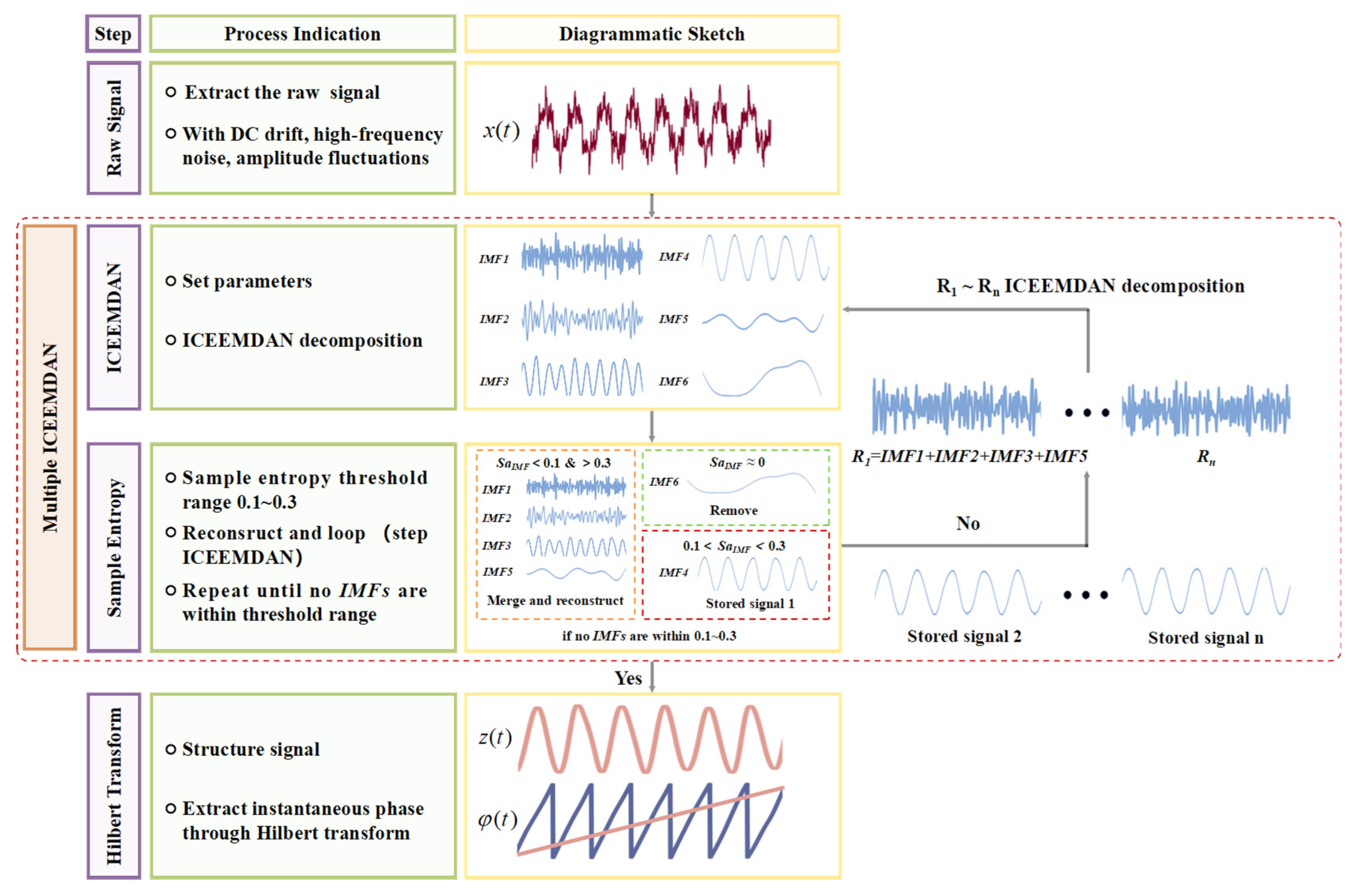
The modal components decomposed by ICEEMDAN of common noise signals are typically selected based on the judgment of discriminant terms for addition and processing to obtain reconstructed signals. However, such a method of directly removing high-frequency and low-frequency components with low correlation may lead to the loss of phase information of interference signal phase unwrapping, as well as insufficient repeatability and stability of phase extraction. Although the advantages of the ICEEMDAN method lie in its ability to reduce modal aliasing and residual noise, further improvement in signal reconstruction quality necessitates secondary processing of both high-frequency and low-frequency intrinsic mode functions (IMFs) obtained through decomposition. Adopting alternative algorithms would significantly decrease the efficiency of signal processing. Therefore, building upon ICEEMDAN, a Multiple ICEEMDAN-HT phase unwrapping method based on sample entropy criteria is proposed to enhance signal reconstruction quality while ensuring the efficiency of signal processing, as shown in Figure 3.
The specific process is as follows:
  • Firstly, the parameters for ICEEMDAN, including the standard deviation of white noise, the number of white noise trials, and the maximum number of iterations, are set. Then, the initial decomposition of the interferogram is performed to obtain the vector representation of IMFs: [ I M F 1 , I M F 2 , , I M F k ] ( k = 1 , 2 , , N )
  • Secondly, the sample entropy threshold is set to 0.1~0.3. By judging whether [ I M F 1 , I M F 2 , , I M F k ] ( k = 1 , 2 , , N ) is within the range of 0.1~0.3, the n th IMFs that reach the threshold standard are saved. The remaining IMFs outside the threshold are summed and reconstructed, and the extremely low component with p th sample entropy values close to zero is removed. The reconstructed signal of one decomposition is obtained and expressed as:
    Y ( t ) ( 1 ) = k = 1 N ( I M F k I M F n I M F p )
  • Repeat step (2) until sample entropy values of all IMFs are outside the threshold range after one decomposition.
  • Afterward, all the saved IMFs from each previous round of decomposition are combined to reconstruct the final signal, which is denoted as z ( t ) :
    z ( t ) = i = 1 N ( I M F n i )
  • The Hilbert Transform (HT) is applied to z ( t ) . HT can be considered as a 90-degree phase shifter, which can also filter out DC drift while realizing phase shift, and is defined as [19]:
    z ( t ) = H [ z ( t ) ] = z ( t ) * 1 π t = 1 π z ( τ ) t τ
In Equation (12), h ( t ) = 1 / π t represents the convolution signal, which can also be referred to as the window function of HT. z ( t ) is expanded in the form of Equation (1) and HT:
{ z ( t ) = b cos Δ φ ( t ) H [ z ( t ) ] = b sin Δ φ ( t )
The instantaneous phase difference in the interference signal is calculated as follows:
Δ φ ( t ) = arctan [ b sin Δ φ ( t ) b cos Δ φ ( t ) ]
6.
Finally, the grating spacing is calculated according to Equation (5).

3. Experiment and Results Analysis

3.1. Simulation Experiment

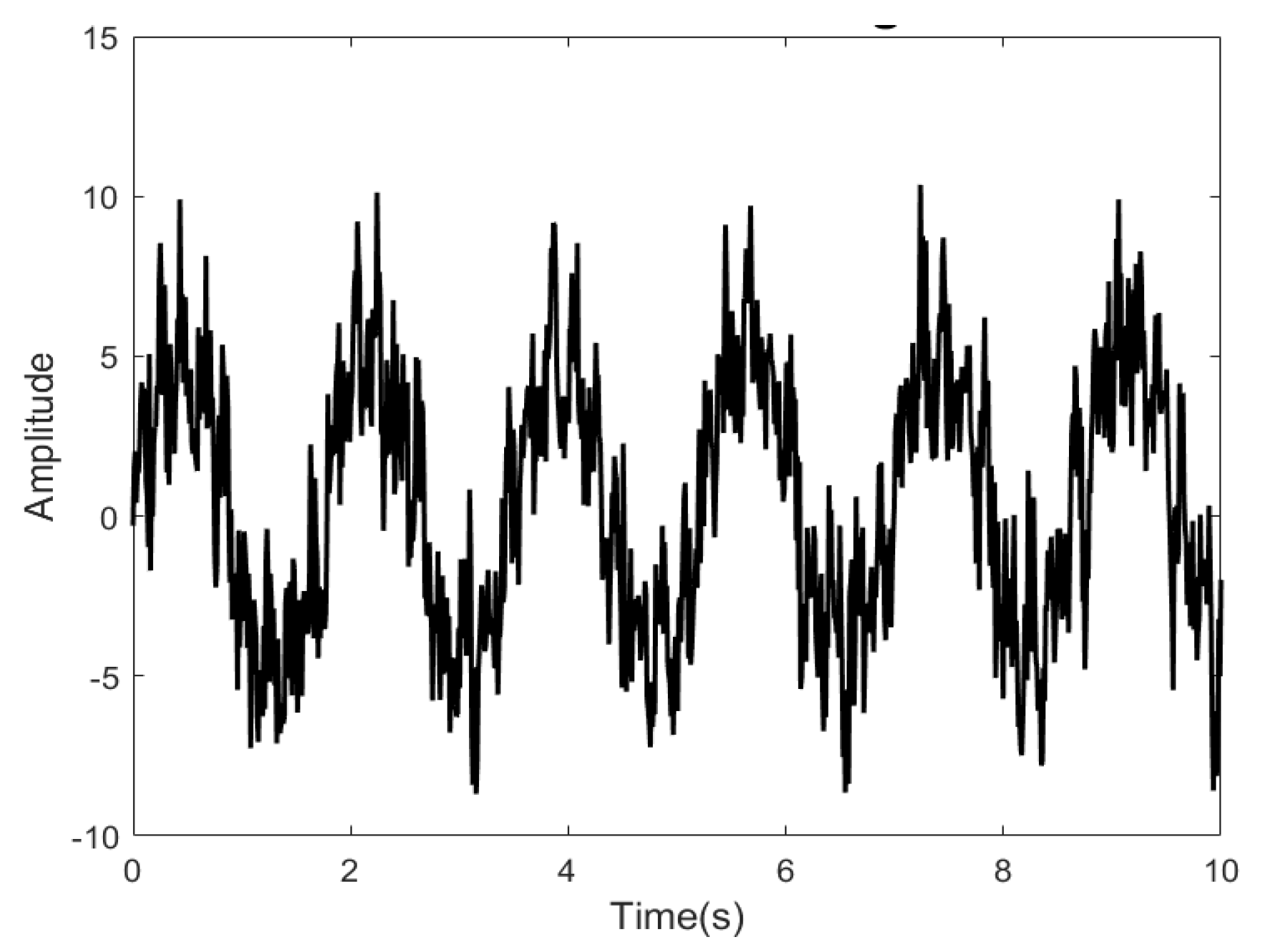
A simulation experiment is adopted in this paper to verify the feasibility of the Multiple ICEEMDAN method based on sample entropy criteria for effectively decomposing and reconstructing signals. A simulated interferometric signal is constructed with a sampling rate of 1000 Hz and a sampling time of 1 s. Additionally, the nonlinear conditions of DC drift, high-frequency noise and distortion are added. The signal-to-noise ratio of the interference signal is 8 dB. The same interference signal is processed by EMD, CEEMD, and ICEEMDAN methods. The time domain diagram of the original signal is shown in Figure 4.

3.1.1. Performance Analysis of Multiple ICEEMDAN

Firstly, the effectiveness and repeatability of the Multiple ICEEMDAN decomposition-reconstruction method using sample entropy as a criterion are analyzed. The initial parameters of ICEEMDAN are set as follows: the standard deviation of white noise is 0.2, the number of noise realizations is 500, and the maximum iteration number is 5000. The sample entropy threshold is set from 0.1 to 0.3, and the Multiple ICEEMDAN algorithm is run 500 times. The upper limit of decomposition levels is set to 10.
The time domain diagram of signal multiple decomposition and reconstruction is shown in Figure 5a. Ten waveforms in the figure, respectively, represent reconstructed signals of order 1 to 10, all of which effectively remove noise burrs. By observing the waveforms selected within the green and orange dashed boxes, it can be observed that the waveforms of the first three orders are relatively intact and similar, indicating good stability. However, from the 4th to the 10th order, varying degrees of fluctuation and distortion are observed in the signal amplitudes. As the number of decomposition and reconstruction increases, the manifestation of amplitude fluctuation and distortion becomes more apparent. Therefore, it is evident that the Multiple ICEEMDAN method is highly effective for noise reduction. Additionally, when the decomposition and reconstruction are limited to the 1st to 3rd orders, complete and undistorted reconstructed signals can be obtained. When the decomposition exceeds the 4th order, over-decomposition tends to occur. Excessive iterations on the same scale result in redundant components covering useful components, leading to the reconstruction signal incorporating these redundant components, thus causing fluctuations in amplitude and distortion.
The distribution of decomposition iterations required based on the sample entropy criterion is depicted in Figure 5b. It is observed that among 500 algorithm runs, 107 instances of 1st order ICEEMDAN decomposition were recorded, representing 21.4% of the total. The most frequent decomposition iterations were for the 2nd order, with 156 occurrences, constituting 31.2% of the total. Additionally, 121 instances of 3rd-order decomposition iterations were identified, accounting for 24.2% of the total. Decomposition iterations for orders 6 through 9 each accounted for less than 1%, while the 10th order had the highest proportion at 6.8% among the higher orders. Based on the aforementioned data, the following can be inferred: ICEEMDAN decomposition iteration based on the sample entropy criterion is mainly concentrated within the first 3 orders. Moreover, a minority of cases exceeding the 5th order may occur. Furthermore, the analysis suggests that when decomposition iterations surpass the 4th order, a tendency towards over-decomposition emerges. This results in the cyclic addition of redundant components with similar sample entropy values, necessitating iteration until reaching the upper limit of the 10th order. This elucidates the higher frequency of occurrences of 10th-order decomposition compared to orders 6 through 9.
In conclusion, the results obtained from the utilization of the Multiple ICEEMDAN method, based on the sample entropy criterion, for the removal of high-frequency noise and distortion from signals, present a promising outlook. Particularly notable is the exceptional integrity and stability demonstrated in signal reconstruction when limiting decomposition iterations to the 1st to 3rd orders. Moreover, the probability of completing iterations within this range stands at approximately 80%, indicating rare occurrences of over-decomposition. This observation highlights the method’s commendable repeatability.

3.1.2. Algorithm Comparative Analysis

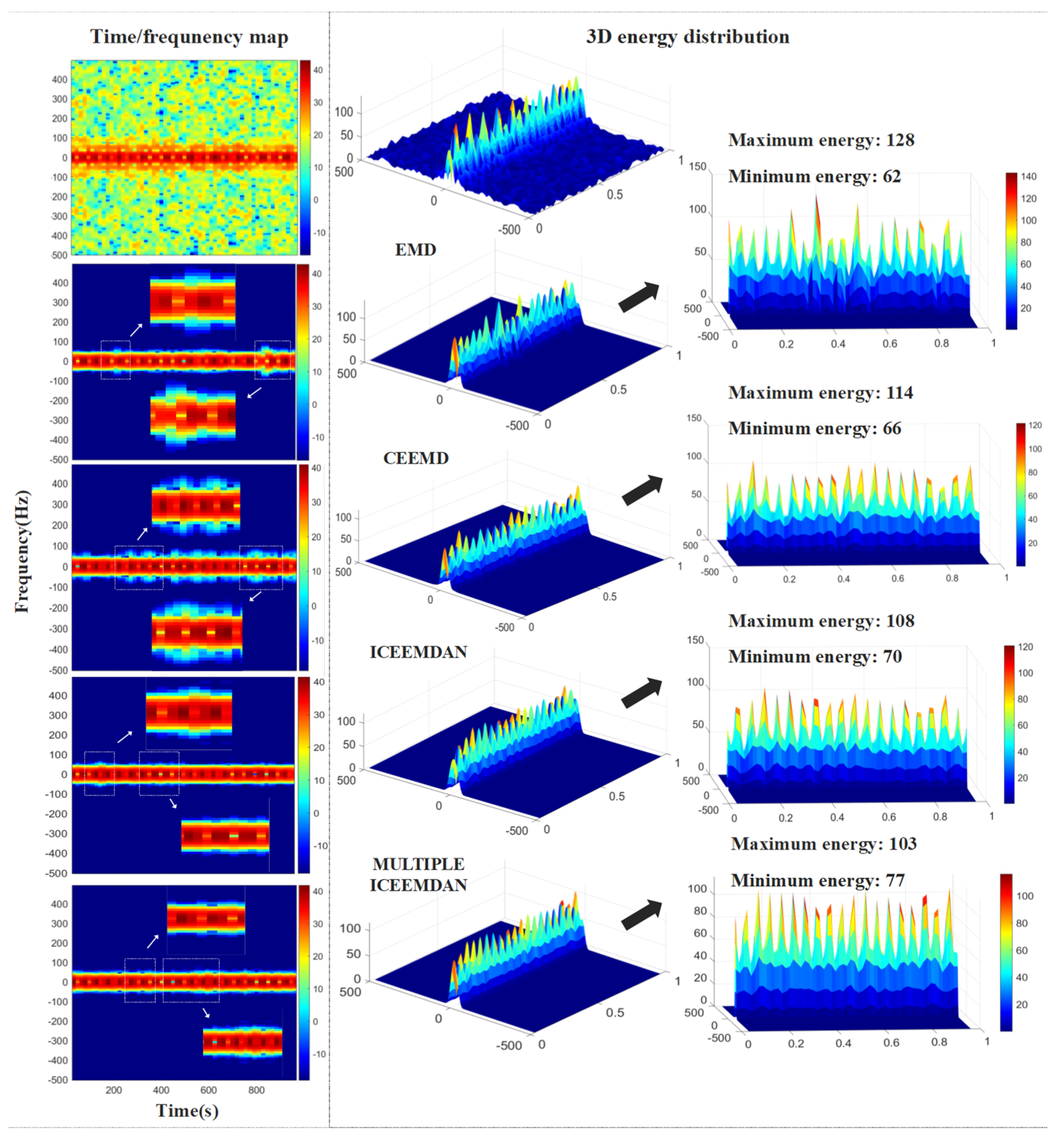
Secondly, for comprehensive evaluation of the decomposition characteristics of the EMD, CEEMD, and ICEEMDAN algorithms in comparison with the Multiple ICEEMDAN method, they are applied to process the signal under nonlinear conditions involving added high-frequency noise, DC drift, and distortion. Equally, the appropriate reconstruction of IMFs is selected based on the sample entropy criterion. In this simulation analysis, the Multiple ICEEMDAN method is applied with a decomposition order of 2.
The signal is depicted in the form of STFT time/frequency diagram, as shown in Figure 6. On the left side, spectrograms of both the original signal and the reconstructed signals using the four algorithms are presented. Meanwhile, on the right side, 3D energy distribution plots are showcased, allowing analysis through color distribution. Upon combining the time/frequency and energy distribution diagrams, it can be observed that all four methods exhibit a degree of capability in noise reduction and distortion mitigation. Nevertheless, the effectiveness of decomposition in EMD and CEEMD is comparatively inferior to that of ICEEMDAN and second-order ICEEMDAN. The EMD algorithm reliant on the distribution of extrema points can encounter confusion when confronted with multiple frequency components, potentially leading to mode mixing phenomena. Upon examination of the local features of the STFT spectrogram derived from EMD, it becomes apparent that not only are high-frequency components diffused, but also incomplete features manifest in the time domain. Furthermore, based on the analysis of the 3D energy distribution, it is observed that the average energy distribution of the signal remains relatively low. This implies that the reconstructed signal is significantly affected by both mode mixing and distortion. The EMD method fails to adequately address the distortion issue and effectively suppress mode mixing. In contrast, the CEEMD method demonstrates enhanced signal continuity, yet it exhibits a more pronounced characterization of regions with higher frequencies. This is attributed to CEEMD’s utilization of white noise pairs addition, which aims to maintain the signal’s fluctuation level consistently across the time domain. While this approach offers the advantage of reducing mode mixing and distortion, it also carries the drawback of potentially generating false modal components and residual noise. As evidenced by the spectrogram of the CEEMD-reconstructed signal, its energy distribution appears more uniform compared to EMD, albeit with small areas exhibiting low energy. In the time/frequency graphs, both ICEEMDAN and second-order ICEEMDAN reconstructed signals appear smoother, and significantly outperform EMD and CEEMD, not only in terms of time domain continuity, but also in the removal of high-frequency components in the frequency domain. This indicates that these two methods effectively address the issues of mode mixing and residual noise from the former, while also mitigating the impact of distortion. Furthermore, upon examination of the 3D energy distribution plots, it is evident that the energy distribution of the reconstructed signals by both methods is relatively uniform. However, ICEEMDAN exhibits a portion of energy with very low magnitude at the edges, whereas second-order ICEEMDAN demonstrates the most uniform distribution.
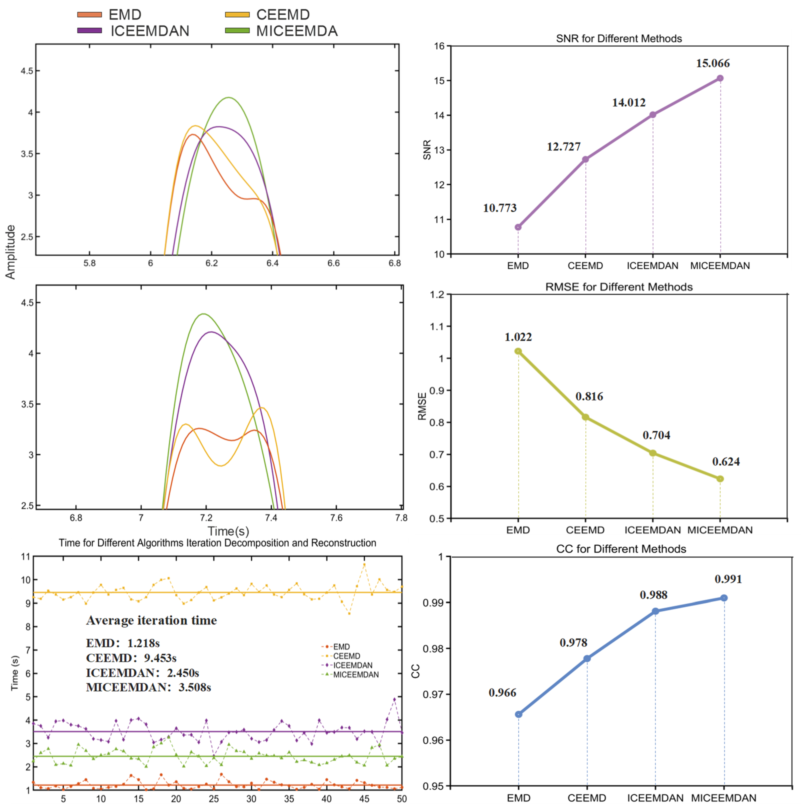
To facilitate a clearer comparison of the decomposition and reconstruction results among the four algorithms, the reconstructed time domain signals are overlaid on the same coordinate axis with localized zooming for analysis. Subsequently, each of the four methods is repeated 50 times, and the time consumed for each iteration of each method is calculated, with the curve being fitted to compare the efficiency of decomposition and reconstruction among algorithms. Finally, three evaluation indicators are employed: root mean square error (RMSE), signal-to-noise ratio (SNR), and correlation coefficient (CC) are employed to calculate the results [30]. The degree of similarity between the reconstructed signal and the original signal is reflected by RMSE and CC, while the degree of signal denoising is reflected by SNR. The calculation formulas of the three evaluation indicators are as follows:
R M S E = 1 N i N ( A i A ^ i ) 2
S N R ( d B ) = 10 × log 10 ( p s i g n a l P n o i s e ) = 10 × log 10 ( i N A i 2 i N ( A i A ^ i ) 2 )
R x y ( k ) = 1 N n = 1 N x ( n ) × y ( n + k )
As shown in Figure 7, the first and second diagrams on the left illustrate localized magnifications of the time domain signal reconstructed by the four methods. The excerpted segment corresponds to the positions of two adjacent peaks within one cycle. It is noteworthy that both EMD and CEEMD represent distortion phenomena on the two peaks, with EMD exhibiting more severe distortion. In contrast, the peaks in the second-order ICEEMDAN signal remain relatively intact compared to the other methods, consistent with the results of the aforementioned time/frequency analysis. The three images on the right display the calculated results of three evaluation metrics for the four methods. Numerically, it can be observed that SNR of second-order ICEEMDAN is the highest at 15.066, the RMSE is the lowest at 0.624, and the CC is 99.1%, all of which outperform the other three methods. The results of ICEEMDAN are also closely aligned with those of the second-order ICEEMDAN, with a CC of 98.8%, SNR of 14.012, and RMSE of 0.704. In the third image on the left, the dashed lines represent the iteration time for 50 repetitions of each method, while the solid lines represent the average iteration time. Among them, EMD exhibits the highest efficiency with an average iteration time of only 1.218 s, while CEEMD necessitates the longest iteration time, requiring approximately 9.453 s per iteration. The average iteration time of ICEEMDAN and second-order ICEEMDAN is 2.450 s and 3.508 s, respectively, approximately twice and three times that of EMD.
Based on the time/frequency analysis and performance comparison of the four methods, it can be seen that the characterization effect of reconstructed signals from EMD and CEEMD is poor. Despite EMD exhibiting the highest iteration efficiency, its performance is significantly hindered by nonlinearity. CEEMD approaches the reconstruction completeness of ICEEMDAN and Multiple ICEEMDAN, but its iteration efficiency is notably poor, thus hindering the attainment of optimal reconstruction results. Multiple ICEEMDAN emerges as the method with the best overall performance, and the completeness and stability of signal reconstruction are verified. However, the addition of sample entropy discrimination in the Multiple ICEEMDAN algorithm introduces an extra process, which increases the total number of global iterations compared to ICEEMDAN. Therefore, its drawback lies in the slightly slower iteration speed compared to ICEEMDAN. Finally, through simulation experiments, the Multiple ICEEMDAN method proposed in this paper can be applied to nonlinear signal decomposition and reconstruction, and effectively remove excess frequency components, which lays a foundation for Hilbert Transform phase unwrapping of reconstructed signals.

3.2. Spacing Calibration Experiment

One-dimensional chromium nanograting standard material developed by Tongji University, also known as self-traceable grating [8], has been approved as a national first-level standard substance. It is used as the standard grating involved in the spacing calibration experiment of homodyne interferometer of dual-grating. The spacing of this standard grating is 212.7705 ± 0.0049 nm, which is rigorously traced back to the natural constant of Cr atoms without measurement. Therefore, by using the self-traceable grating as the standard grating of the spacing calibration system, the shortcomings of ordinary diffraction grating which are prone to engraving errors and periodic errors can be overcome. The planar reflective grating with 3600 lines is selected as the grating to be measured. The specific parameters of both the self-traceable grating and the planar grating are summarized in Table 1.
As shown in Figure 8, the spacing calibration system for homodyne interferometer of dual-grating is set in a 10,000-class optical clean laboratory and placed on an optical air float platform. The ambient temperature is kept at 20 ± 0.5 °C and the humidity is kept in the range of 55 ± 10%. As a light source, the output beam size of the external-cavity diode laser (ECDL) at 405 nm ranges from 1 to 3 mm, with the far-field divergence angle being less than 2 mrad. It is typically operated in a narrow linewidth state of less than 500 kHz. The piezoelectric driven nano positioning stage (P66.X60S) is used as the driving device. Due to the influence of the driving frequency of the displacement stage on the quality of the interference signal, the driving frequency has been determined to be 1 Hz after multiple adjustments to ensure that the interference signal reaches its optimal state. The signals are simultaneously collected by silicon band amplification detector (PDA10A2) and data acquisition card (NIcDAQ-9174). The main experimental parameters are set as follows: the output voltage range is ±10 V, the sampling frequency is 10 kHz, the single sampling time is 0.1 s, and there are 1000 sampling points.
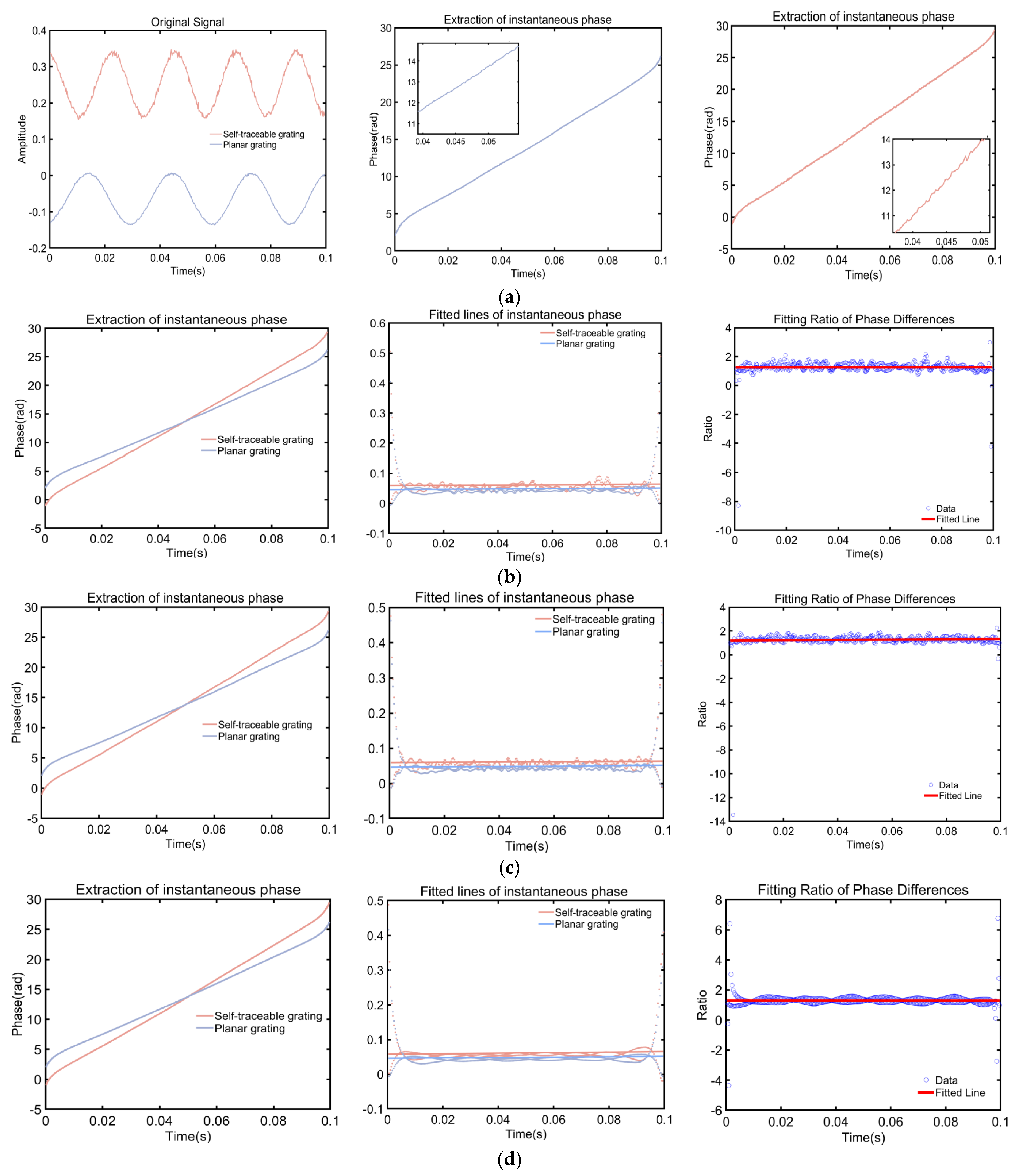
The initial interference signal sequence of the dual-grating is synchronously collected by the data acquisition card. After extracting a segment of signals from the dual-grating within the same time interval of 0.1 s, the EMD-HT, CEEMD-HT, ICEEMDAN-HT, and Multiple ICEEMDAN-HT methods are, respectively, employed for decomposition and reconstruction. The phase difference within 0~0.1 s is solved by phase unwrapping the reconstructed signal. Finally, the phase difference in the self-traceable grating and the planar grating, along with the spacing of the known self-traceable grating, are substituted into Equation (5), allowing the calibration of the spacing of the planar grating. The initial interference signal of the dual-grating and the phase unwrapping with Hilbert Transform are illustrated in Figure 9a. It can be seen from the detailed diagram that the Hilbert Transform is directly utilized to extract the phase of the original signal. However, the influence of nonlinear factors is relatively significant, and the phase information cannot be accurately provided, resulting in a substantial spacing measurement error. Hence, further calibration of the grating spacing is required using this method. Figure 9b–e represent the results obtained by employing the four aforementioned methods for phase unwrapping.
As shown in Figure 9b–e above, progressing from left to right, the diagrams showcase the following: the instantaneous phase expansion diagram of the self-traceable grating and planar grating, the instantaneous phase difference between adjacent time points along with the fitted line, the ratio of the fitted lines for the instantaneous phase differences in the dual-grating, and the fitted line for the ratio. Given that the Hilbert Transform is prone to produce boundary effects, as shown in the left figure, the method of fitting is adopted to enhance calculation accuracy and mitigate boundary impact. Finally, the phase difference ratio of the two gratings within 0~0.1 s can be calculated by averaging each point on the ratio fitting line. Therefore, the phase differences and their ratios between the reference grating and the test grating are given, as well as the known spacing of the reference grating, the spacing of the test grating can be calculated using the proportion Equation (5). The calculation results are presented in Table 2.
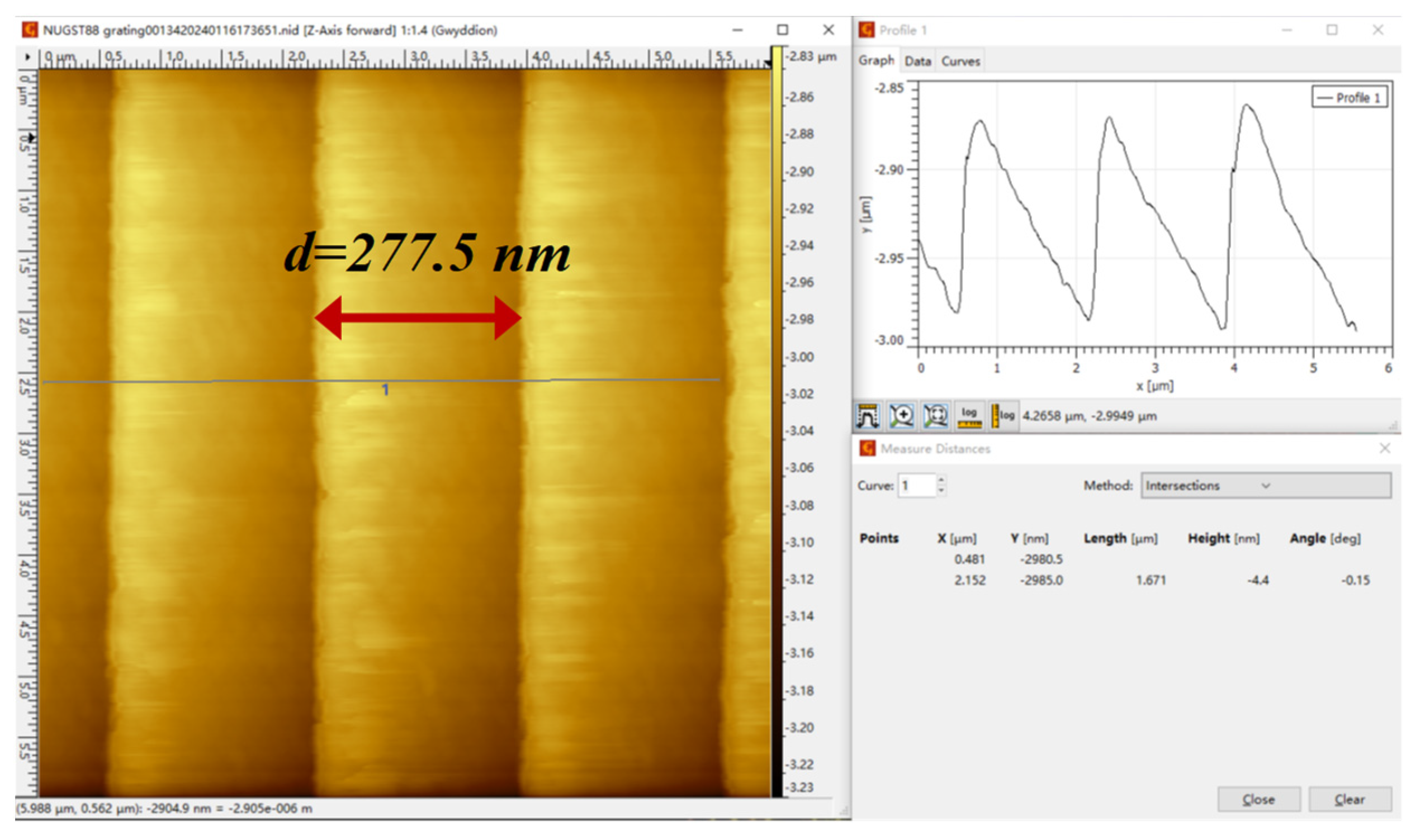
In order to compare the phase extraction results of the four methods with a unified standard, the planar grating is scanned and measured by the Atomic Force Microscopy (AFM) calibrated with the self-traceable standard material. As shown in Figure 10, within any 10 μm × 10 μm region in the effective evaluation area, after obtaining the average spacing of the planar grating through 30 consecutive scans and processing it with various reasonable algorithms, the relatively accurate period of the grating is determined to be 277.5 nm. The spacing calibration results of this experiment are compared with the AFM measurement results, which serve as the standard, as shown in Table 2. The results indicate that calibration for the 3600-line plane grating can be achieved by all four methods. Among them, the EMD-HT method exhibits the poorest calibration effect, with a calibrated spacing of 265.4 nm, a standard deviation of 12.1 nm, and a relative error of 4.36%. Conversely, the Multiple ICEEMDAN-HT method demonstrates the best calibration effect, with a calibrated spacing of 277.3 nm, a standard deviation of 0.2 nm, and a relative error of only 0.07%. Compared with the other three methods, the accuracy is increased by 4.29%, 1.51%, and 0.61%, respectively. Thus, it can be concluded that the method proposed in this paper effectively enhances the robustness of the signal and the stability of distance measurement, leading to a significant improvement in phase accuracy.

4. Discussion

In this paper, a signal decomposition and phase unpacking method of Multiple ICEEMDAN-HT is proposed. Firstly, the principle of the dual-grating homodyne interference spacing measurement system and the algorithm principle of ICEEMDAN are explained, and then the sample entropy criterion is creatively added on the basis of ICEEMDAN. The processing process of Multiple ICEEMDAN-HT is analyzed and summarized. Through the double verification of simulation and experiment, the feasibility of the Multiple ICEEMDAN method is proved, and the algorithm has good repeatability. The method can also effectively improve the robustness and stability of the signal, reduce the influence of nonlinear factors, and improve the measurement accuracy. It can be summarized as follows:
  • In contrast to conventional signal decomposition methods where IMFs require secondary processing with other signal processing methods to obtain the final result, the extraction of IMFs in the Multiple ICEEMDAN method relies on the sample entropy criterion. This ensures an effective signal decomposition while also enhancing the efficiency of signal reconstruction.
  • The Multiple ICEEMDAN method eliminates the phenomenon of mode mixing compared to EMD, resulting in a more complete decomposition. Compared to CEEMD, it reduces residual components and enhances decomposition efficiency. Compared to ICEEMDAN, the method increases the accuracy of reconstructed signals.
  • The multiple ICEEMDAN-HT method is an exceptionally effective phase unwrapping technique, capable of improving the precision of grating phase extraction to the nanometer level.
  • The multiple ICEEMDAN-HT method focuses on the decomposition, reconstruction, and phase extraction of interference signals. Therefore, whether it is a reflective or transmissive grating, this method can be applied to calibrate it.
Furthermore, the Multiple ICEEMDAN-HT method can also be further researched in the future in the following aspects:
  • The iteration efficiency of Multiple ICEEMDAN is not ideal, thus necessitating the exploration of more advanced and rapid techniques to replace the sample entropy criterion, such as energy characteristics and singular spectrum analysis, to enhance the evaluation of algorithmic convergence behavior.
  • The Multiple ICEEMDAN method can be combined with other signal processing techniques to conduct a more in-depth analysis of signal characteristics, thereby being applied to more complex nonlinear and non-stationary signal processing.

5. Conclusions

This paper addresses the nonlinear influences on ranging of dual-grating. The Multiple ICEEMDAN-HT phase unwrapping method based on the sample entropy criterion is proposed, built upon the ICEEMDAN algorithm. Experimental verification is conducted using a practical dual-grating ranging system. Compared with several existing signal decomposition and reconstruction methods, the Multiple ICEEMDAN-HT method achieves a calibration relative error as low as 0.07%, with higher calibration accuracy than other signal decomposition methods. The results demonstrate that the robustness of signals and the stability of distance measurement can be effectively enhanced through the Multiple ICEEMDAN-HT phase unwrapping method based on the sample entropy criteria. Additionally, the impact of nonlinear factors on phase accuracy can be reduced. This method holds significant application significance for the research of real-time signal measurement and instantaneous processing efficiency.

Author Contributions

Conceptualization, Y.Z. (Yanzhen Zhu); methodology, Y.Z. (Yanzhen Zhu); software, Y.Z. (Yanzhen Zhu); validation, J.S., Y.G. and C.G.; formal analysis, Y.G.; investigation, L.L. (Liqin Liu) and C.G.; resources, Y.Z. (Yanzhen Zhu) and Y.Z. (Yujie Zhang); data curation, Y.Z. (Yanzhen Zhu); writing—original draft preparation, Y.Z. (Yanzhen Zhu); writing—review and editing, Y.Z. (Yanzhen Zhu) and J.S.; visualization, L.L. (Lihua Lei) and J.W.; supervision, L.L. (Lihua Lei); project administration, L.L. (Lihua Lei); funding acquisition, L.L. (Lihua Lei) and J.S. All authors have read and agreed to the published version of the manuscript.

Funding

This research was Sponsored by Shanghai Natural Science Foundation [Grant No. 21ZR1483100], and Program of Shanghai Academic/Technology Research Leader [Grant No. 21XD1425000], Program of Shanghai Municipal Administration for Market Regulation [Grant No. D00RJ2310], National Key Research and Development Program for Young Scientists project [Grant No. 2021YFF0603300].

Institutional Review Board Statement

Not applicable.

Informed Consent Statement

Not applicable.

Data Availability Statement

Data are contained within the article.

Conflicts of Interest

The authors declare no conflicts of interest.

References

  1. Yin, Y.F.; Liu, Z.W.; Jiang, S.; Wang, W.; Yu, H.Z.; Jiri, G.; Hao, Q.; Li, W.H. High-precision 2D grating displacement measurement system based on double-spatial heterodyne optical path interleaving. Opt. Lasers Eng. 2022, 158, 107167. [Google Scholar] [CrossRef]
  2. Dominique, P.; Virginie, C.; Vincent, M. Integrated optics interferometer for high precision displacement measurement. In Proceedings of the SPIE, International Conference on Space Optics—ICSO 2000, Toulouse Labège, France, 5–7 December 2000. [Google Scholar]
  3. Cocco, D.; Sostero, G.; Zangrando, M. Technique for measuring the groove density of diffraction gratings using the long trace profiler. Rev. Sci. Instrum. 2003, 74, 3544–3548. [Google Scholar] [CrossRef]
  4. Liu, B.; Wang, Q.P.; Xu, X.D.; Fu, S.J. Measurements of groove density for concave gratings with the long trace profiler. Rev. Sci. Instrum. 2006, 77, 046106. [Google Scholar] [CrossRef]
  5. Xie, Y.F.; Jia, W.; Zhao, D.; Ye, Z.H.; Sun, P.; Xiang, C.C.; Wang, J.; Zhou, C.H. Traceable and long-range grating pitch measurement with picometer resolution. Opt. Commun. 2020, 476, 126316. [Google Scholar] [CrossRef]
  6. Xiang, X.S.; Jia, W.; Xiang, C.C.; Li, M.K.; Bu, F.T.; Zhou, C.H.; Wei, C.L. Long-range in situ picometer measurement of the period of an interference field. Appl. Opt. 2019, 58, 2929–2935. [Google Scholar] [CrossRef] [PubMed]
  7. Zhu, J.H.; Wang, G.C.; Wang, S.T.; Li, X.H. A Reflective-Type Heterodyne Grating Interferometer for Three-Degree-of-Freedom Subnanometer Measurement. IEEE Trans. Instrum. Meas. 2022, 71, 7007509. [Google Scholar] [CrossRef]
  8. Deng, X.; Dai, G.L.; Liu, J.; Hu, X.K.; Bergmann, D.; Zhao, J.; Tai, R.Z.; Cai, X.Y.; Li, Y.; Li, T.B.; et al. A new type of nanoscale reference grating manufactured by combined laser-focused atomic deposition and x-ray interference lithography and its use for calibrating a scanning electron microscope. Ultramicroscopy 2021, 226, 113293. [Google Scholar] [CrossRef] [PubMed]
  9. Zhou, W.Y.; Liu, Z.W.; Sun, Y.J.; Teng, H.R.; Wang, W.C.; Bayanheshig; Li, W.H. Bidirectional Littrow double grating interferometry for quadruple optical interpolation. Opt. Laser Technol. 2024, 175, 110751. [Google Scholar] [CrossRef]
  10. Josef, L.; Miroslava, H.; Jan, H.; Jindřich, O.; Ondřej, Č.; Miloslav, V.; Petra, S.; Milan, P. Advanced interferometry systems for dimensional measurement in nanometrology. In Optics and Measurement Conference; SPIE: Philadelphia, PA, USA, 2014. [Google Scholar]
  11. Hu, P.C.; Chang, D.; Tan, J.B.; Yang, T.R.; Yang, H.X.; Fu, H.J. Displacement measuring grating interferometer: A review. Front. Inf. Technol. Electron. Eng. 2019, 20, 631–654. [Google Scholar] [CrossRef]
  12. Du, H.; Zhang, W.T.; Xiong, X.M.; Zeng, Q.L.; Wang, Y.L.; Zhang, Y.T. Influence of installation error of grating interferometer on high-precision displacement measurement. Opt. Eng. 2021, 60, 045102. [Google Scholar] [CrossRef]
  13. Deng, X.; Li, T.B.; Cheng, X.B. Self-traceable grating reference material and application. Opt. Precis. Eng. 2022, 30, 2608–2625. [Google Scholar]
  14. Shang, P. Study on the Key Technology of High-Resolution Diffraction Grating Interferometric Transducer of Linear Displacements; Hefei University of Technology: Hefei, China, 2012. [Google Scholar]
  15. Yang, J.; Huang, J.H.; Lei, Y.H.; Zheng, J.B.; Shan, Y.Z.; Guo, D.Y.; Guo, J.C. Analysis of period and visibility of dual phase grating interferometer. Chin. Phys. B 2022, 31, 058701. [Google Scholar] [CrossRef]
  16. Wang, B.Z.; Li, W.J.; Peng, K.; Wang, Q.; Li, M.L. Time Domain Subdivision Method for Optical Grating Signal Based on Time Series Analysis. Nanotechnol. Precis. Eng. 2018, 1, 48–53. [Google Scholar]
  17. Wu, W.B.; Yuan, X.J. Analyzing spectral peak distribution of coupled signals using Fourier transform theory. Indian J. Phys. 2023, 97, 4509–4519. [Google Scholar]
  18. Yang, Z.H.; Yang, G.R.; Yang, L.H.; Zhang, Q. A reconstruction method for graph signals based on the power spectral density estimation. Digit. Signal Process. 2022, 122, 103347. [Google Scholar] [CrossRef]
  19. Saqib, A. Implementation of hilbert transform based high-resolution phase unwrapping method for displacement retrieval using laser self mixing interferometry sensor. Opt. Laser Technol. 2022, 149, 107887. [Google Scholar]
  20. Zhang, Y.J.; Xu, L.; Guan, Y.Q.; Zou, W.Z.; Guo, C.W.; Lei, L.H.; Fu, Y.X.; Guo, Z.Y.; Gu, Z.J.; Deng, X. Research on laser self-mixing nano-displacement measurement based on plane reflective holographic grating. Infrared Laser Eng. 2023, 52, 235–242. [Google Scholar]
  21. Eduardo, A.; Mario, E.; José, M.E.; Calixto, M.; Gerry, L.; Carlos, B. Comparison between traditional fast Fourier transform and marginal spectra using the Hilbert–Huang transform method for the broadband spectral analysis of the electroencephalogram in healthy humans. Eng. Rep. 2021, 3, e12367. [Google Scholar]
  22. Huang, N.E.; Shen, Z.; Long, S.R.; Wu, M.C.; Shih, H.H.; Zheng, Q.; Yen, N.C.; Tung, C.C.; Liu, H.H. The empirical mode decomposition and hilbert spectrum for nonlinear and non-stationary time series analysis. Proc. R. Soc. 1998, 454, 903–995. [Google Scholar] [CrossRef]
  23. Deng, W.; Liu, Z.G.; Deng, Z.W.; Jia, X.Y.; Wang, Z.Y. Extraction of interference phase in frequency-scanning interferometry based on empirical mode decomposition and Hilbert transform. Appl. Opt. 2018, 57, 2299–2305. [Google Scholar] [CrossRef]
  24. Yang, K.Y.; Deng, Z.W.; Chen, W.J.; Yao, X.; Sun, H.F.; Shen, L.R. Phase-extracting method of optical frequency scanning interference signals based on the CEEMD-HT algorithm. Chin. Opt. 2023, 16, 682–700. [Google Scholar]
  25. Tan, J.S.; Ran, Z.; Wan, C. EEG signal recognition algorithm with sample entropy and pattern recognition. J. Comput. Methods Sci. Eng. 2023, 23, 2059–2068. [Google Scholar] [CrossRef]
  26. Zhou, W.Y.; Li, W.H.; Liu, L.; Sun, Y.J.; Wang, W.C.; Chen, G.X.; Liu, Z.W. Bidirectional two-degree-of-freedom grating interferometer with biased Littrow configuration. Opt. Commun. 2024, 557, 130333. [Google Scholar] [CrossRef]
  27. Lv, Q.; Liu, Z.W.; Wang, W.; Jiang, S.; Bayanheshig; Li, W. Fast method to detect and calculate displacement errors in a Littrow grating-based interferometer. Appl. Opt. 2019, 58, 3193–3199. [Google Scholar] [CrossRef]
  28. Wu, Z.H.; Huang, N.E. ENSEMBLE EMPIRICAL MODE DECOMPOSITION: A NOISE-ASSISTED DATA ANALYSIS METHOD. Adv. Adapt. Data Anal. 2009, 1, 1–41. [Google Scholar] [CrossRef]
  29. Xiao, M.H.; Wang, Z.Y.; Zhao, Y.F.; Geng, G.S.; Dustdar, S.; Donta, P.K. A new fault feature extraction method of rolling bearings based on the improved self-selection ICEEMDAN-permutation entropy. ISA Trans. 2023, 143, 536–547. [Google Scholar] [CrossRef]
  30. Hua, Z.; Gao, B.K.; Yue, H.Y.; Cui, X.Y. Vibration measurement based on square arithmetic and multiple Hilbert transform for F—P interferometry. Laser Infrared 2021, 51, 1065–1069. [Google Scholar]
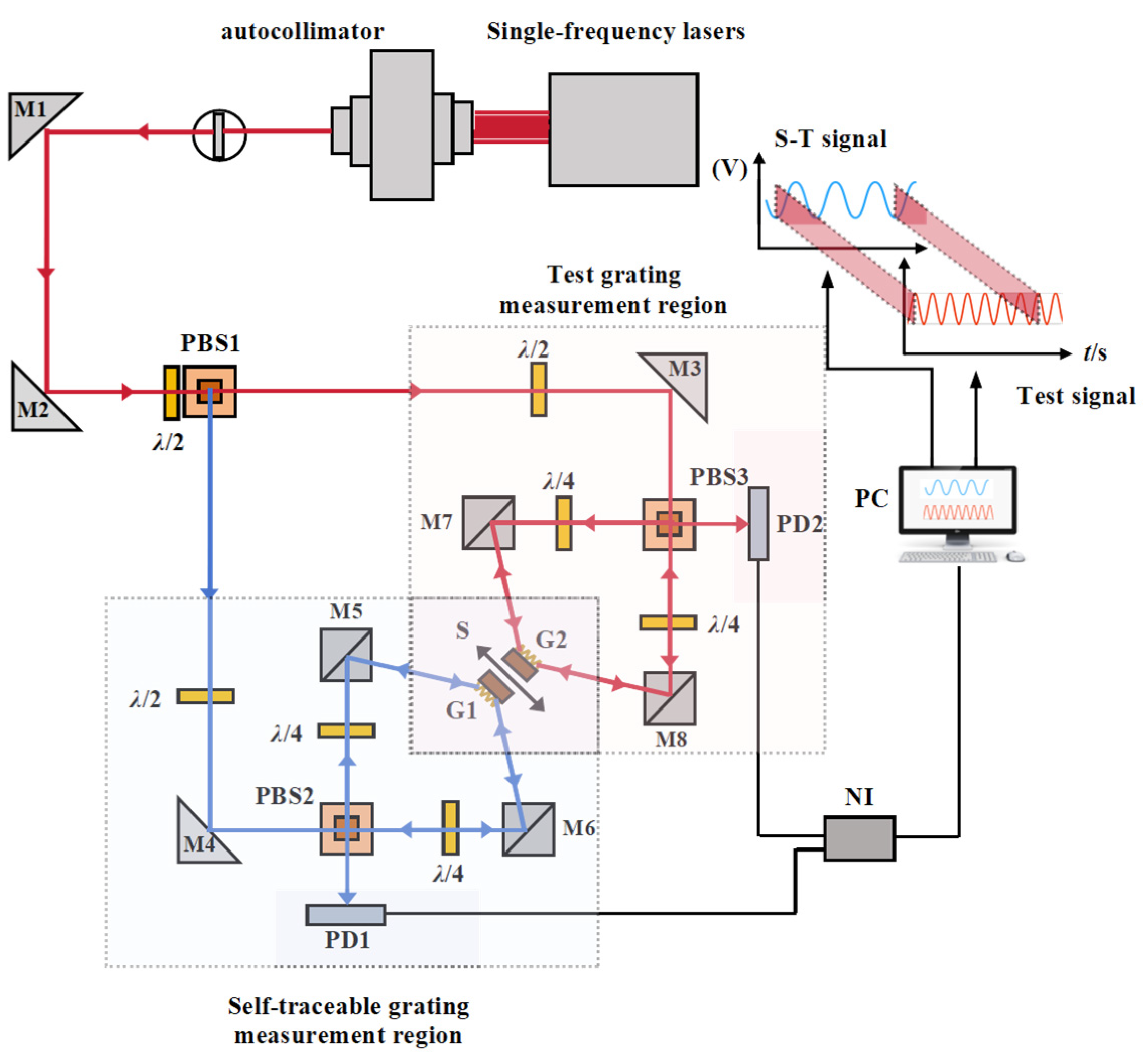
Figure 1. Schematic diagram of the homodyne interference measurement system of dual-grating for spacing calibration. The red lines and red boxed areas represent the test grating path, while the blue lines and blue boxed areas represent the self-traceable grating path.
Photonics 11 00443 g001
Figure 2. The flowchart of ICEEMDAN algorithm principle.
Photonics 11 00443 g002
Figure 3. Phase unwrapping method based on sample entropy criterion for Multiple ICEEMDAN-HT.
Photonics 11 00443 g003
Figure 4. Time domain plot of the raw interference signal.
Photonics 11 00443 g004
Figure 5. (a) Signal multiple decomposition and reconstruction; (b) distribution of sample entropy iteration counts in 500 runs.
Photonics 11 00443 g005
Figure 6. Time/frequency analysis of reconstructed signals using different methods.
Photonics 11 00443 g006
Figure 7. Performance comparison of reconstructed signals using different methods.
Photonics 11 00443 g007
Figure 8. Homodyne interference measurement system with the dual-grating for spacing calibration.
Photonics 11 00443 g008
Figure 9. (a) The initial interference signal of the dual-grating and the phase unwrapping with Hilbert Transform; (b) EMD-HT; (c) CEEMD-HT; (d) ICEEMDAN-HT; (e) Multiple ICEEMDAN-HT.
Photonics 11 00443 g009aPhotonics 11 00443 g009b
Figure 10. AFM scanning results of the plane grating.
Photonics 11 00443 g010
Table 1. The relevant technical parameters for self-referencing grating and planar grating.
The Type of GratingSelf-Traceable GratingPlanar Grating
Grating area materialCr/
Substrate materialSiFloat glass
Size/mm1.5 × 325 × 25 × 6
Linear density (Lines/mm)47003600
Spacing standard value/nm212.7705 ± 0.0049277.8
Littrow angle at maximum diffraction efficiency ( θ )72.5°46.8°
Table 2. The spacing calibration results for the 3600 lines planar grating.
Phase Unwrapping MethodPhase Difference Ratio within 0 to 0.1 sCalibration Spacing for This Experiment/nmSpacing Average of AFM Scans/nm
277.5
Std/nmRe/%
EMD-HT1.2474265.412.14.36
CEEMD-HT1.2836273.14.41.58
ICEEMDAN-HT1.2954275.61.90.68
Multiple ICEEMDAN-HT1.3033277.30.20.07
Disclaimer/Publisher’s Note: The statements, opinions and data contained in all publications are solely those of the individual author(s) and contributor(s) and not of MDPI and/or the editor(s). MDPI and/or the editor(s) disclaim responsibility for any injury to people or property resulting from any ideas, methods, instructions or products referred to in the content.