1. Introduction
With the rapid development of modern mobile communication services, wireless spectrum resources are becoming increasingly scarce. And the probability of interference between wireless signals has increased significantly. Using higher frequency terahertz (THz) communications can effectively alleviate the increasingly tight spectrum resources and the capacity constraints of current wireless systems. The THz wave with a wavelength range of 30 μm to 1 mm is an electromagnetic spectrum between the millimeter wave and infrared ray [
1,
2,
3,
4]. Compared with microwave communication, THz communication has a larger transmission capacity, better confidentiality, and stronger anti-interference ability. And THz communication has low photon energy and good penetration of dust and smoke compared with optical communication, which can ensure the reliability of communications in harsh environments [
5,
6,
7,
8,
9]. However, the development of related functional devices, such as the THz antenna and filter, is essential to realize efficient THz communication [
10,
11,
12].
The THz antenna is primarily employed for the mutual conversion of current and electromagnetic waves, as well as the transmission and receiving of electromagnetic waves in THz communication. As is known to all, the THz microstrip antenna has an important application in the field of THz communication due to its low profile, small size, simple processing, and easy integration [
13,
14,
15]. However, the main challenges faced by researchers are that the surface wave loss of the traditional homogeneous substrate used for the THz microstrip antenna deteriorates the return loss, reduces the gain and radiation efficiency, and the single-frequency THz microstrip antenna cannot meet the current requirements of the multi-band operation and high transmission rates of communication systems [
16,
17].
The new concept of ultra-small antennas was introduced in [
18], which integrates a high dielectric constant substrate and subwavelength resonators to achieve multi-band operation. The performance of the antenna is typical for ultra-small antennas of such size, whereas its capability of high transmission rates remains under question. Hajian et.al discusses the effects exerted by different substrates’ permittivity on the propagation and localization characteristics of surface plasmon polaritons (SPPs) in single-layer graphene. However, the substrate material can affect the transmission characteristics of graphene and have an impact on antenna performance [
19]. Li et al. investigated the effect of changing the properties of nearby substrates on the propagation distance of plasma. When the proximal substrate is very thin, the plasma is strongly dampened by the substrate, resulting in a very short propagation distance [
20]. Photonic crystal represents a nanostructure comprising periodically located implants in a host medium, which is designed for electromagnetic wave propagation in any direction and is completely prohibited for all frequencies within a stopband. As a result of this periodicity, the transmission of light is zero in specific frequency ranges, which are called photonic band gaps (PBG). By introducing the defects in these periodic structures, the periodicity and, thus, the completeness of the PBG are entirely broken, which can control and manipulate the light. This means that photonic band gaps (PBGs) are widely used in optical devices [
21]. In order to design an excellent performance THz microstrip antenna, adopting the photonic band gap (PBG) substrate, which can be achieved by implanting different materials such as metallic, dielectric, and ferromagnetic in the substrate cavity, is an attractive method [
22]. The PBG substrate has a unique characteristic called the frequency band gap, which can limit the propagation of electromagnetic waves within the band gap range by periodically varying the dielectric constant. Due to the influence of the frequency band gap, it is possible to suppress the surface wave loss, as well as to lower the return loss and increase the antenna gain [
23]. Moreover, the multi-frequency response of PBG substrate THz microstrip antenna (PBG antenna) can be achieved by forming a multilayer-substrate structure with the PBG substrate and other dielectric constant substrates.
Previous studies have shown that the air-hole PBG substrate is widely employed in the design of a single-frequency THz microstrip antenna to reduce the return loss and improve the gain [
24,
25,
26,
27]. Ullah et al. designed a rectangular split ring air-hole PBG antenna with return loss reduced from −31.48 dB to −34.9 dB and gain increased from 6.86 dB to 6.884 dB at 0.696 THz compared to the homogeneous substrate THz microstrip antenna (H antenna) [
28]. Elizabeth et al. devised a PBG antenna by boring air holes with the array of the triangular lattice structure on a dielectric substrate and, compared with the H antenna, the return loss decreased from −25.64 dB to −57.81 dB and the directivity increased from 6.5 dB to 7.68 dB at 2.37 THz [
29]. Kumar et al. presented a periodic circular air-hole substrate THz microstrip antenna with return loss decreased from −20.745 dB to −44.71 dB and gain increased from 6.59 dB to 7.94 dB at 0.63 THz compared to the H antenna [
30]. Sunil et al. designed a circular slot terahertz antenna on the PBG substrate, which could achieve two frequency operations. Compared with the H antenna, this PBG antenna reduced the return loss from −28.86 dB and −23.89 dB to −68.53 dB and −32.72 dB, respectively. However, the maximum gain of PBG antenna is 3.43 dB [
31]. The air-hole PBG antenna can achieve multi-band operation but does not significantly improve gain.
In contrast to the earlier work on antennas using the air-hole PBG substrate, a high-gain and tri-band PBG antenna is presented in this paper. The gain of the antenna is enhanced significantly by implanting polyimide rectangular dielectric columns into the silicon substrate to make the PBG substrate. It is realized the tri-band operation of the THz microstrip antenna is due to the PBG substrate and polyimide substrate having a multilayer substrate structure. The gains of the PBG antenna are 6.28 dB, 4.84 dB, and 7.66 dB at three resonant frequencies of 0.360 THz, 0.580 THz, and 0.692 THz, which are 1.18 dB, 1.74 dB, and 1.82 dB higher than that of the H antenna, respectively. The return losses of PBG antenna are −31.4 dB, −19.3 dB, and −64.1 dB, respectively, which shows a large drop of 46.2 dB at 0.692 THz, and a slight increase at 0.360 THz and 0.580 THz due to the interaction between resonance points compared to that of the H antenna. Additionally, the radiation efficiencies at three operating bands are over 93%, 92%, and 88%, respectively, which are slightly higher than that of the H antenna and greater than that of the standard multi-band antenna.
2. Antenna Design
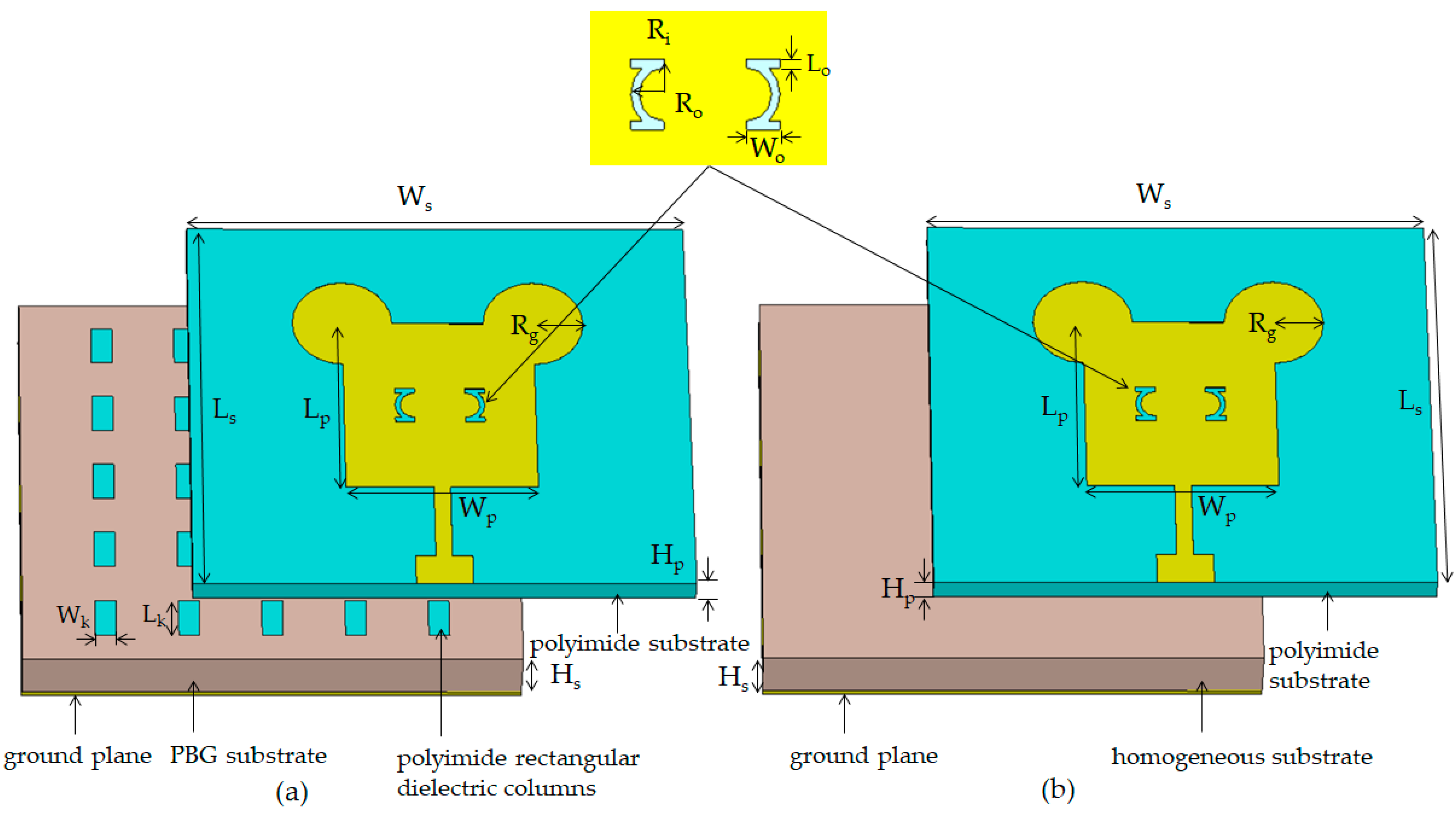
Figure 1a shows the geometry and dimensions of the PBG antenna. The antenna simulated by CST microwave studio has a certain degree of convergence and accuracy. In order to give better accuracy in terms of resonant frequency, the CST microwave studio was used to create an antenna model to study the optimized size of PBG antennas. This model uses a time-domain solver, with the mesh type set to hexagonal and the boundary conditions set to periodic. The PBG antenna consists of a ground plane as the bottom layer, a rectangle patch as the top layer, and a PBG substrate and a polyimide substrate sandwiched between the ground plane and rectangle patch. The ground plane is made by conducting material gold with the length and width of L
s × W
s = 260 μm × 300 μm.
As the antenna radiator, the parameters of the rectangular patch can be calculated by the following equations [
32]. The rectangle patch width W
p can be computed by
, where c is the speed of light in free space, f
r is the desired resonance frequency, and ε
r is substrate permittivity. The rectangle patch length L
p is calculated from
, where the effective dielectric constant of the rectangle patch ε
reff is given by
, and the fringing fields’ extended length is given by
, in which h is the thickness of the polyimide substrate. In this paper, the width W
p and length L
p of the rectangle patch are theoretically calculated by equations and determined at 115 μm and 120 μm as the final values obtained through simulation optimization.
Two parasitic [
33] circular patches with radii of R
g = 30 μm are installed at the rectangle patch to increase the radiation area and improve the impedance bandwidth of the PBG antenna. The slots, made of a half-ring with outer radius R
o of 12 μm and inner radius R
i of 9 μm and two rectangles with a length and width of L
o × W
o = 3 μm × 12 μm, are etched on the rectangle patch. The slots on the patch are used to change the original current’s distribution and reduce the return loss of the antenna [
34,
35]. The PBG antenna is excited through a 50 Ω microstrip feed line.
It should be noted that the characteristic impedance z
0 of microstrip lines can be expressed as:
or
[
36], where w is the width of the conductor strip line, and h is the thickness of the dielectric layer. ε
eff is the effective dielectric constant, and the formula is as follows:
where ε
r is the dielectric constant of the dielectric layer [
36]. According to the parameters of the designed antenna, the characteristic impedance of the microstrip line can be obtained at about 50 Ω. The maximum transmission frequency of the microstrip lines is determined by the cutoff frequency, which can be expressed as:
, where η
0 is the characteristic impedance of free space, and c
0 is the speed of light in a vacuum. Through calculation, the cutoff frequency of terahertz waves is 2 THz. Therefore, the antenna feed is suitable for the terahertz range. According to the formula of Ohmic loss,
[
36], where σ and μ
0 represent the metal conductivity (σ = 45.2 × 10
6 S/m) and free space magnetic permeability (μ
0 = 1.26 H/m), f
r is the resonant frequency value of silicon substrate antenna, and
z0 is the characteristic impedance. The calculated Ohmic loss (α
c = 2.96 × 10
−3 dB/m) of the antenna is very small, and it has almost no impact on the output characteristics.
The PBG substrate with a length, width, and height of L
s × W
s × H
s = 260 μm × 300 μm × 35 μm is placed on the ground plane and obtained by implanting the 5 × 5 arrays of the polyimide (dielectric constant ε
r = 3.5 and loss tangent tan δ = 0.0027) rectangular dielectric columns in the silicon (ε
r = 11.9 and tan δ = 0.00025) substrate. Considering the size of the PBG substrate, the periodicity of the polyimide rectangular dielectric column is 50 μm. In order to create an antenna array structure, femtosecond laser direct writing is used to process the material layer by layer, and then the photonic crystal array is embedded into the substrate using the optimal assembly method [
8]. The polyimide substrate with a height of H
p = 15 μm, bonded on the PBG substrate using prepreg as the multilayer-substrate structure, adjusts the electromagnetic resonance frequency and realizes the multi-band operation of the antenna.
Figure 1b shows the geometry and dimensions of the H antenna. Except for the fact that the PBG substrate is replaced by a homogeneous substrate, other geometries and dimensions are the same as those of the PBG antenna in
Figure 1a. To clearly observe the difference between PBG and homogeneous substrates, the distances between them and the polyimide substrate are increased.
3. Results and Discussion
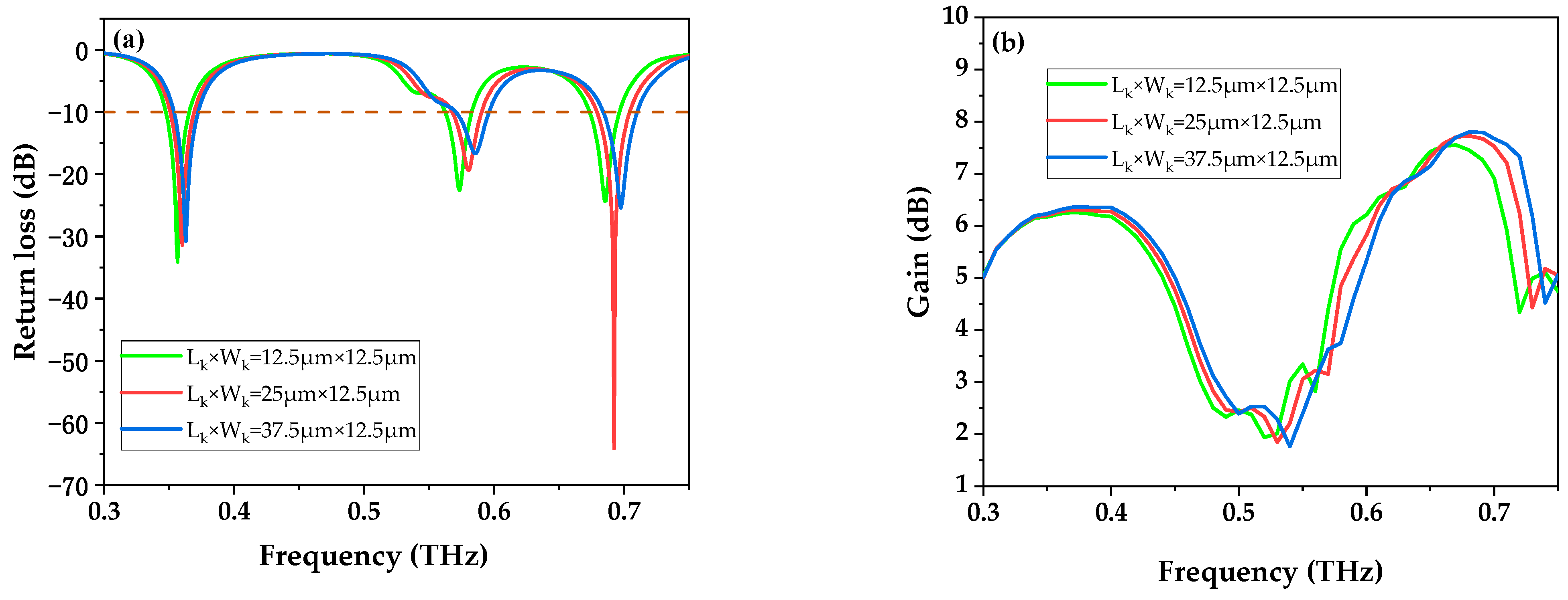
In order to optimize the return loss and gain of the PBG antenna, the impact of the length (L
k) and width (W
k) of the rectangular dielectric column on return loss and gain in the range of 15–35 μm and 7.5–17.5 μm was investigated, respectively, as shown in
Figure 2. The return loss is the ratio of reflected power to incident power at the transmission line port, as represented by S
11 (dB), and the formula is:
, where
zi is the load impedance and
z0 is the characteristic impedance, which should be less than −10 dB for effective utilization (mark the position with a horizontal red dashed line in all return loss pictures) [
37], as shown by the underline in
Figure 2a. It can be seen that the resonance frequencies of the PBG antenna are increased with L
k and W
k. According to the formula in the previous text, it can be inferred that when the polyimide rectangular dielectric column arrays of different sizes are embedded in a substrate, the dielectric constant of the dielectric layer changes. Therefore, the return loss of the PBG antenna experiences a big change with L
k and W
k. And the return loss of the PBG antenna with L
k × W
k = 25 μm × 12.5 μm is the lowest, −64.1 dB, which is plotted by a red solid line in
Figure 2a. The gain is presented as the ratio of the energy current density between the directional antenna’s maximum radiation direction and the isotropic uniform radiation antenna. It can be seen from
Figure 2b that with the increase in L
k and W
k, the gain of three resonant frequencies exhibits a slight increase. But the corresponding return loss deteriorates. Therefore, in this paper, the length and width of the rectangular dielectric column for the PBG antenna were chosen to be L
k × W
k = 25 μm × 12.5 μm.
Figure 3 shows the effect of different proportion sizes of the dielectric column on the antenna. In
Figure 3a, when the aspect ratio of the dielectric column is 2:1 (L
k × W
k = 25 μm × 12.5 μm), the PBG antenna has the lowest return loss at 0.692 THz. As can be seen from
Figure 3b, the gain of the PBG antenna with different proportion sizes of the dielectric column does not vary significantly. Overall, when the ratio of L
k to W
k is 2:1, the antenna performance is the best.
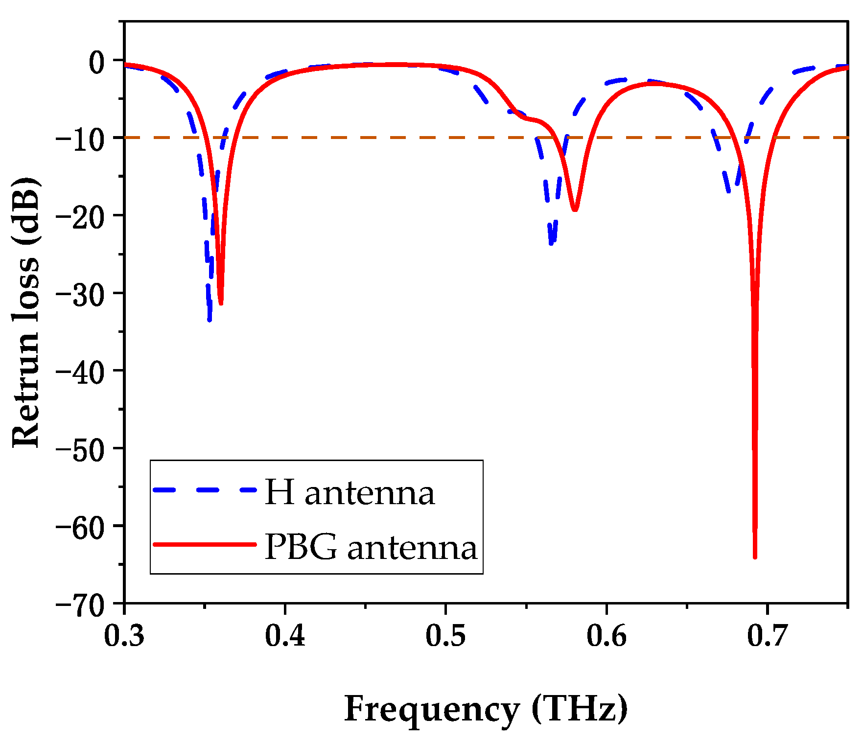
Figure 4 shows the comparison of return loss between the PBG antenna (red solid curve) and the H antenna (blue dotted line). Compared with the H antenna, the resonant frequencies of the PBG antenna are shifted to a high band slightly due to the dielectric constant changing in the PBG substrate by the presence of rectangular polyimide dielectric columns. It can be seen from
Figure 4 that there are three resonant frequencies of 0.360 THz, 0.580 THz, and 0.692 THz for the PBG antenna, which exhibited the −10 dB bandwidths of 0.019 THz, 0.022 THz, and 0.025 THz, respectively. The −10 dB bandwidths of the H antenna are 0.018 THz, 0.093 THz, and 0.02 THz, respectively. Compared with the H antenna, the return loss of the PBG antenna resulted in massive decreases of 46.2 dB, from −17.9 dB to −64.1 dB, at 0.692 THz. At 0.360 THz and 0.580 THz, the return losses increased from −34 dB to −31.4 dB and −24 dB to −19.3 dB, respectively, due to the interaction between the resonance points, which still met the operating requirement of below −10 dB.
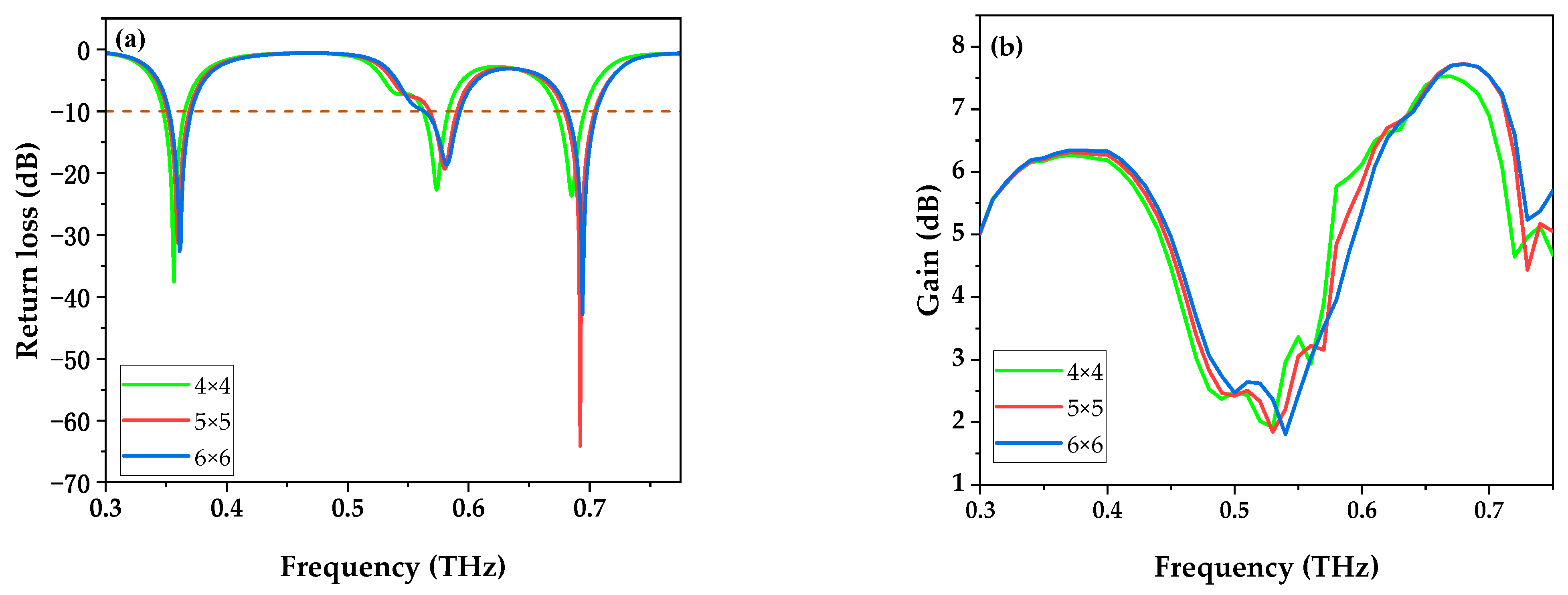
In order to investigate the effect of the dielectric cylinder period on antenna performance, the return loss of the PBG antenna with different periods of dielectric columns is shown in
Figure 5a. When the period of the rectangular dielectric column of the PBG antenna is 5 × 5, the antenna has the lowest return loss at 0.692 THz. As shown in
Figure 5b, there is no clear difference in the gain of the PBG antenna with different dielectric column periods. Therefore, the polyimide rectangular dielectric columns with a period of 5 × 5 when embedded into the substrate can significantly improve the performance of the antenna.
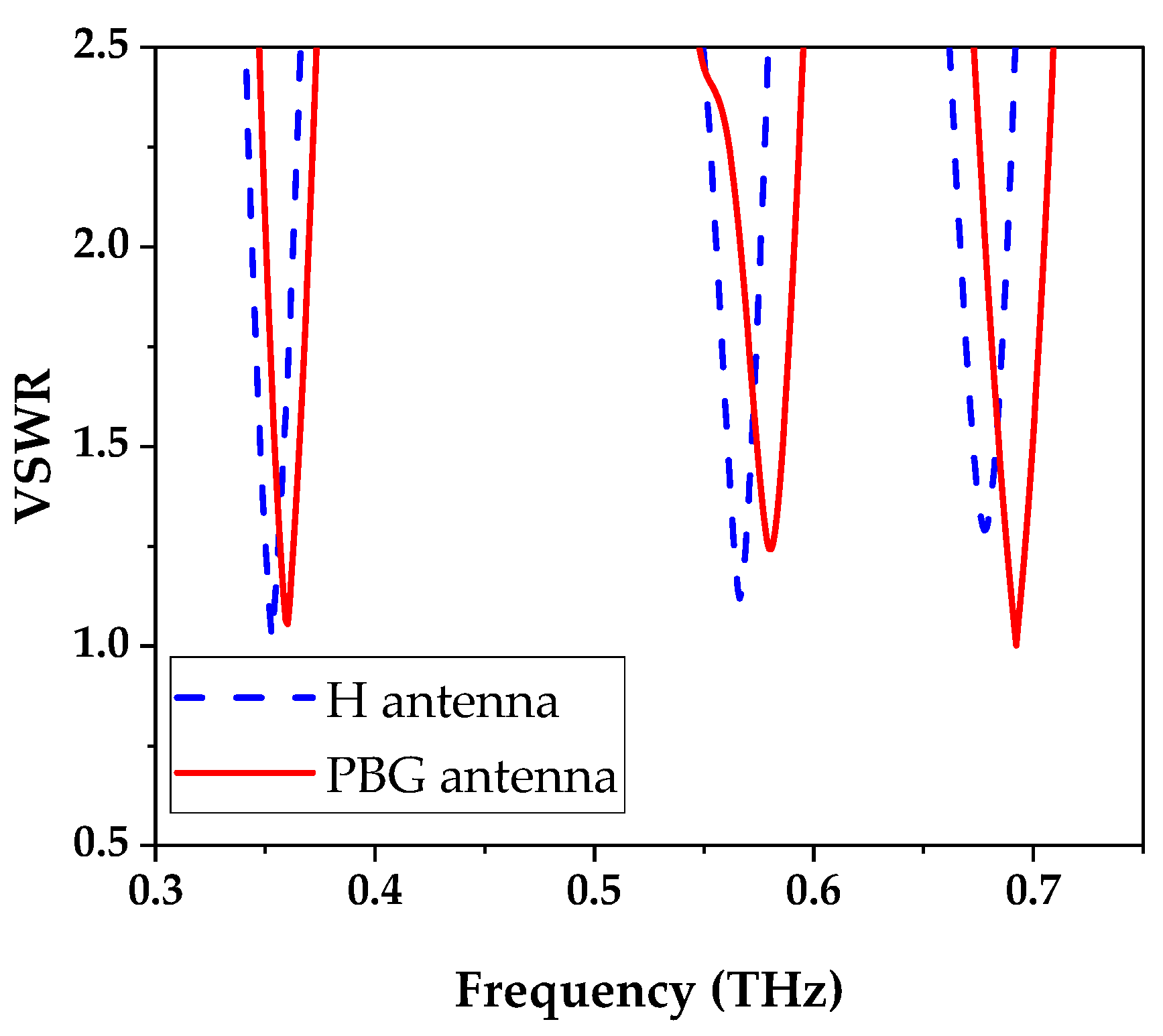
Figure 6 depicts the voltage standing wave ratio (VSWR) for the PBG antenna. VSWR is the ratio of the wave pitch voltage to the standing wave belly voltage. It is positively correlated with return loss and reveals the signal reflected back to the source owing to the mismatch between the impedance of the source and antenna. In addition, the closer the VSWR is to one, the smaller the reflection from the antenna impedance and the higher the transmission efficiency of the antenna. As shown in
Figure 6, the minimum VSWR of the PBG antenna is 1.0012, which can be attained at a resonant frequency of 0.692 THz, which is very close to the ideal value of 1, and satisfies and validates the condition for perfect impedance matching, while that of the H antenna (blue dotted line) is 1.289, far away from 1, at 0.679 THz. At 0.360 THz and 0.580 THz resonant frequencies, the VSWRs of the PBG antenna (red solid line) are 1.055 and 1.242, respectively, which are a great distance from 1, compared with the 1.018 and 1.119 values of the H antenna (blue dotted line) at resonant frequencies of 0.352 THz and 0.566 THz.
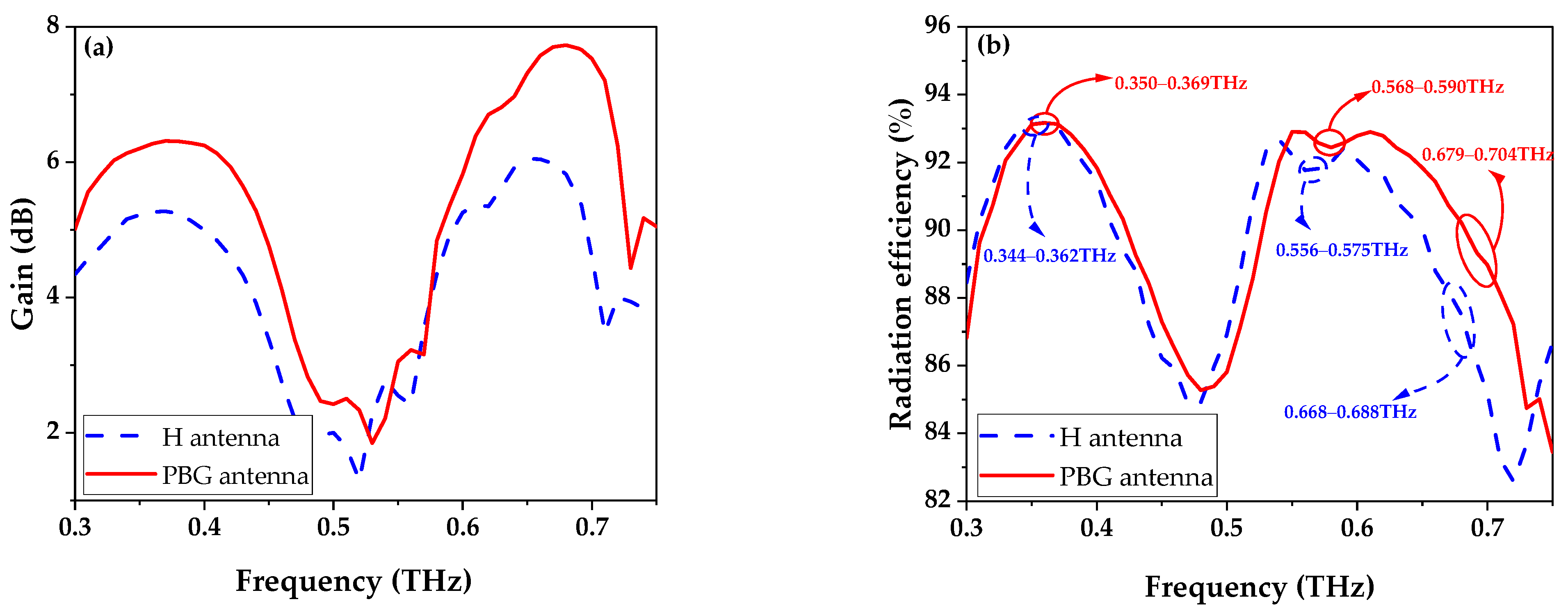
Figure 7 shows the gain and radiation efficiency of the PBG antenna. The radiation efficiency is defined as the ratio of the radiation power to the net input power of the antenna. The gain and radiation efficiency are used to measure the radiation capability and energy conversion of the antenna, respectively. According to
Figure 7a, the PBG antenna (red solid line) achieves gains of 6.28 dB, 4.84 dB, and 7.66 dB at resonant frequencies of 0.360 THz, 0.580 THz, and 0.692 THz, respectively, which are 1.18 dB, 1.74 dB, and 1.82 dB greater than that of the H antenna (blue dotted line), respectively. For easier observation, in
Figure 7b, the operating bands of the PBG antenna and H antenna are indicated by red and blue circles, respectively.
Figure 7b demonstrates the radiation efficiencies of over 93%, 92% and 88% of the PBG antenna at three operating bands of 0.350–0.369 THz, 0.568–0.590 THz, and 0.679–0.704 THz, respectively, which are slightly higher than that of the H antenna, whose radiation efficiencies are over 93%, 91%, and 86% at operating bands of 0.344–0.362 THz, 0.556–0.575 THz, and 0.668–0.688 THz, respectively.
The 2D radiation patterns of the PBG antenna at 0.360 THz, 0.580 THz and 0.692 THz resonance frequencies are shown in
Figure 8. The radiation pattern reflects the distribution of the radiation field of the antenna with the spatial position.
Figure 8a shows the 2D radiation patterns of the PBG antenna at 0.360 THz. It demonstrates that the maximum directivity of 6.63 dBi occurs at an elevation angle og φ = 0° and azimuth angle pf θ = 0° for 0.360 THz.
Figure 8b presents the 2D radiation patterns of the PBG antenna at 0.580 THz. According to
Figure 8b, the maximum directivity of 5.36 dBi occurs at φ = 90° and θ = 64° for 0.580 THz. And
Figure 8c shows that, at 0.692 THz, the maximum directivity of 8.23 dBi occurs at φ = 90° and θ = 51°.
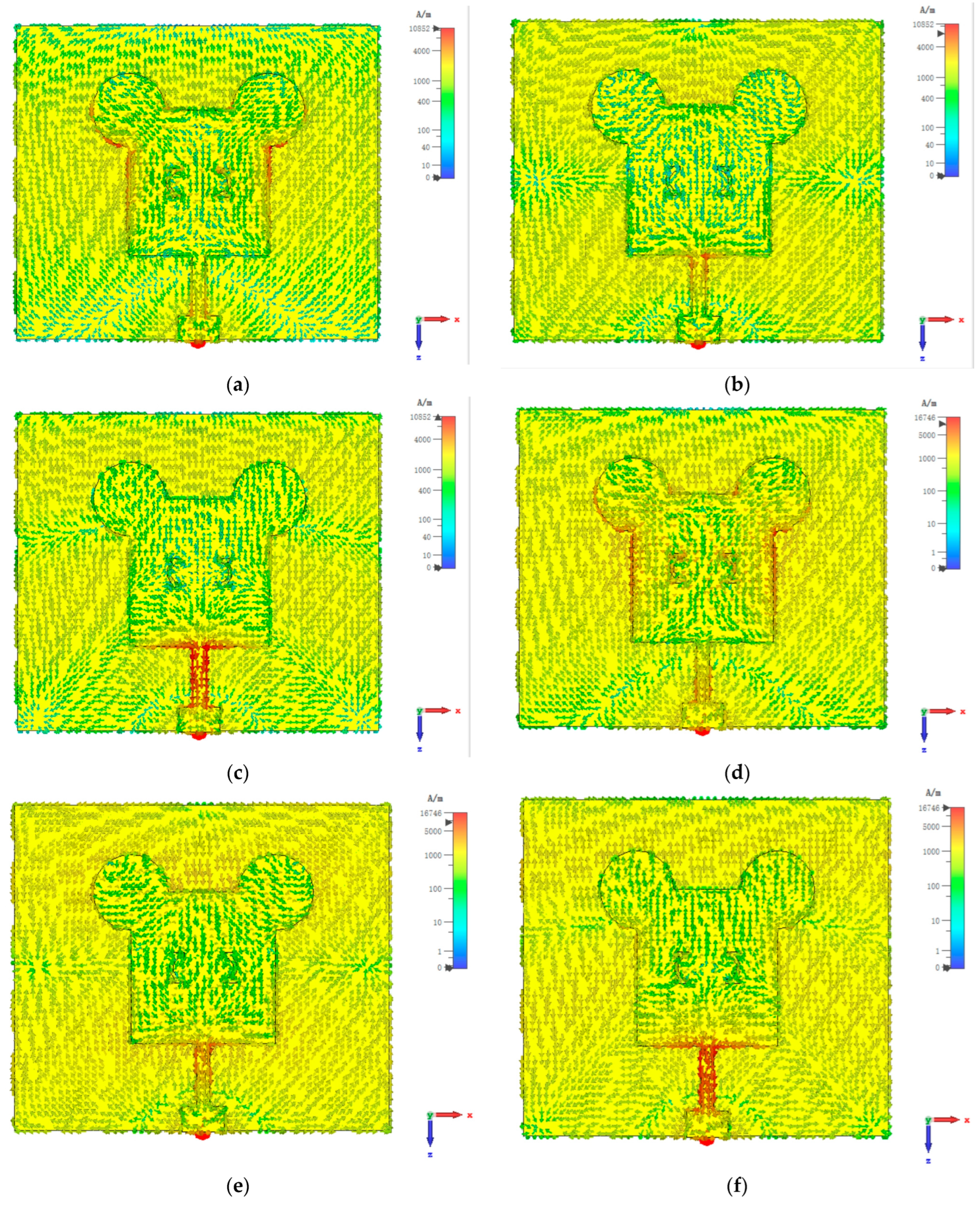
The surface current distributions of the H antenna (0.353 THz, 0.566 THz, and 0.677 THz) and PBG antenna (0.360 THz, 0.58 THz, and 0.692 THz) at three resonance points are shown in
Figure 9a–f. The current intensity on the PBG antenna patch is stronger than that on the H antenna. This is because the antenna uses the PBG substrate to suppress surface waves, and the surface current flows towards the patch, making the current intensity on the patch strong and radiating more energy, thereby improving antenna performance.
It is necessary to analyze the fabrication errors of the antenna. By changing the slot width from 2 to 3.5 μm, the return loss and radiation efficiency of the antenna can be obtained, as shown in
Figure 10. As shown in
Figure 10a, when the slot width is changed, the return loss only changes at the resonant point of 0.692 THz. In
Figure 10b, the variation in slot width hardly affects the radiation efficiency of the antenna. The variation in the return loss with the slot width at 0.692 THz is shown in
Figure 10c. When the width range is 2.94–3.08 μm, the return loss remains around −64 dB, as shown in red dashed lines. Based on the above analysis, it can be concluded that the slot width of 2.94–3.08 μm is the allowable error range for equipment processing.
The return loss, gain, and radiation efficiency of PBG antenna are compared with the prevailing multi-band antennas, as illustrated in
Table 1. Upender et al. proposed a cylindrical dielectric resonator THz antenna with gains of 5 dB, 4.5 dB, 5.5 dB, and 6.67 dB at the resonant frequencies of 8.79 THz, 11.10 THz, 13.73 THz, and 16.21 THz, respectively. And the radiation efficiency of the cylindrical dielectric resonator THz antenna was over 85% for all operating bands [
38]. Bokhari et al. designed a graphene-based THz microstrip antenna using a two-element diversity system with return losses of −29 dB, −49 dB, −55 dB, and −99 dB and gains of 4.5 dB, 4.8 dB, 5 dB, and 5.2 dB at 1.57 THz, 2.08 THz, 3.32 THz, and 4.43 THz, respectively. And the radiation efficiency of the antenna was over 70% for all operating bands [
39]. Vijayalakshmi et al. investigated a graphene-based two-element array microstrip antenna with return losses of −24 dB, −30 dB, and −48 dB at 2.3 THz, 3.2 THz, and 4.5 THz, respectively. At all operating bands, the gain was over 5 dB, and the radiation efficiency was over 60% [
40]. Compared with the prevailing multi-band antennas, the PBG antenna achieves lower return losses of −31.4 dB, −19.3 dB, and −64.1 dB, higher gains of 6.28 dB, 4.85 dB, and 7.66 dB at 0.360 THz, 0.580 THz, and 0.692 THz, and greater radiation efficiencies of over 88% at all operating bands, respectively.
4. Conclusions
In this paper, a high-gain and tri-band THz microstrip antenna with rectangular polyimide dielectric columns for the PBG substrate is presented. The PBG substrate, which is created by embedding 5 × 5 polyimide rectangular dielectric columns into a silicon substrate, is used to reduce the surface wave loss and enhance the gain of the antenna. By employing PBG and polyimide substrates as a multilayer substrate structure, the PBG antenna is able to attain tri-band operational characteristics. At resonate frequencies of 0.360 THz, 0.580 THz, and 0.692 THz, the PBG antenna achieves return losses of −31.4 dB, −19.3 dB, and −64.1 dB, and VSWR of 1.055, 1.242, and 1.0012, respectively. The gains of the PBG antenna for the three resonate frequencies are 6.28 dB, 4.85 dB, and 7.66 dB, respectively, which are 1.18 dB, 1.74 dB, and 1.82 dB greater than that of the H antenna. Moreover, the radiation efficiencies of the PBG antenna are over 93%, 92%, and 88% at three operating bands, respectively, which are slightly higher than those of the H antenna and better than those of the prevailing multi-band antenna. The results reveal that the PBG antenna has high gain, high radiation efficiency, and tri-band operations, which are extremely important in the prospective THz broadband wireless communication system.
