1. Introduction
Nanometrology is a precise measurement technology at the nanoscale, which is the basis of advanced nanomanufacturing technology. Among the various aspects of nanometrology, traceability is recognized as a fundamental issue, which is, of course, a difficult and complex task [
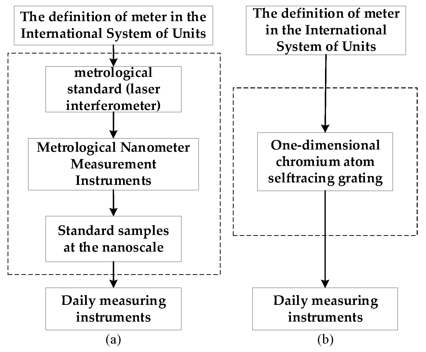
1]. The flow chart of a typical transfer chain of nanometrology traceability to the International System of Units (SI) is shown in
Figure 1a. Using the laser wavelength of the laser interferometer as the length measurement reference, the laser wavelength in the air is susceptible to the refractive index; thus, the accuracy of the measurement results relies on the calibration and correction of the measurement process [
2]. Traditional calibration methods based on measuring the refractive index of the air are limited by the harsh application conditions, and the correction level of relative measurement accuracy is limited to the order of 10
−6, which has not been broken for a long time. Compared with conventional nanometrology traceability systems, the nanometrology traceability system established based on the Cr grating, as shown in
Figure 1b, which uses the Cr grating period as the traceability reference, effectively shortens the traceability chain and realizes the calibration and traceability of Atomic Force Microscope (AFM), Scanning Electron Microscope (SEM) and other metrology instruments. It also ensures the accuracy and comparability of their measurement results, reduces the accuracy and comparability of nanometrology, and reduces the traceability error introduced by the nano-standard sample and the micro- and nano-measuring instruments in the process of transferring the measurement values [
3,
4].
In 2021, a one-dimensional 212.8 nm self-traceable Cr grating was fabricated by the Nano-metrology Group at Tongji University using atomic lithography [
1], where the grating period can be directly traced back to the wavelength corresponding to the transition level of the Cr atom. Also, its application is no longer limited to the metrological calibration of metrological instruments such as AFM, SEM, etc. This is due to the self-traceability of the Cr grating period as well as advancements in grating fabrication [
3,
4,
5,
6]. The group used a self-traceable Cr grating for precision displacement measurement systems, realizing the direct traceability of nanometer measurements [
7].
In order to promote the application of self-traceable gratings in the field of ultra-precision displacement measurement, the self-traceable grating as well as the diffraction characteristics need to be studied and analyzed in detail. However, there are currently few studies on the diffraction characteristics of self-traceable gratings.
The diffraction efficiency of the grating is mainly affected by the grating material, grating period, grating groove shape, grating groove depth, laser wavelength, laser beam incident angle, and other factors. If all influencing factors are considered simultaneously and comprehensively, the analysis will be very complicated and cumbersome. The purpose of this study is to analyze the effect of the grating incident angle in detail and to thereby calculate the change rule of the diffraction efficiency of the grating with the laser beam incident angle. This is done according to the practical application of the grating measurement system and based on the grating structure parameters and laser wavelength. In this study, according to the self-traceable grating structure and laser incident conditions, and also based on the vector diffraction theory and by adopting the strict coupled wave method, we establish a theoretical model for the diffraction efficiency of self-traceable gratings. The self-traceable grating structure is simplified as a sine-type structure and layered. According to the model, we obtain the exact solutions of Maxwell’s equations, which satisfy the electromagnetic field boundary conditions when the laser beam is incident on self-traceable grating. Additionally, we analyze the effect of the laser incident angle on the diffraction efficiency of the grating.
2. Theory
2.1. Chromium Gratings with Self-Traceable Characteristics
Cr gratings with self-traceable properties are fabricated by atom lithography. Atom lithography, also known as laser convergent atomic deposition, is a technique for fabricating one-dimensional gratings based on the interaction of light and atoms. The pitch of a one-dimensional grating is determined by the jump frequency of atoms, which is a natural constant, and therefore, the pitch of the grating fabricated by atom lithography has self-traceable properties [
1,
8].
Figure 2 shows the schematic of Cr atom lithography [
8], which selects the Cr jump frequency
7S
3→
7P
4 as the natural reference and strictly locks the laser wavelength at 425.6 nm corresponding to this jump frequency, so that the collimated Cr atom beams are orthogonally deposited on the substrate through the standing wave field formed by the above opposite wavelengths. Also, the Cr atoms converge to the position of wave bellies or wave nodes corresponding to the standing wave field, forming a periodic parallel sinusoidal grating structure on the substrate. Furthermore, the grating period is strictly traceable to the laser half-wavelength, which is characterized by self-traceability [
8]. According to the fabrication method of the self-traceable grating, the grating size is 1 mm × 3 mm, the grating cross-section is sinusoidal, the grating area material is Cr, the substrate material is Si, and the grating pitch is 212.8 nm [
9].
Tongji University [
1] has fabricated the self-traceable grating by using atomic lithography technology. Additionally, the grating groove depth of the Cr grating fabricated by Tongji University was up to 53 nm. The grating groove is deeply affected by the light source power, exposure time, photoresist properties, lithography equipment parameters and other factors. This research mainly analyzes the effect of the laser incident angle on the diffraction efficiency of the grating, and the depth of the grating groove is not taken as the main research. Therefore, this research adopts the Cr grating with a grating groove depth of 15 nm fabricated by Tongji University.
2.2. Rigorous Coupled-Wave Method
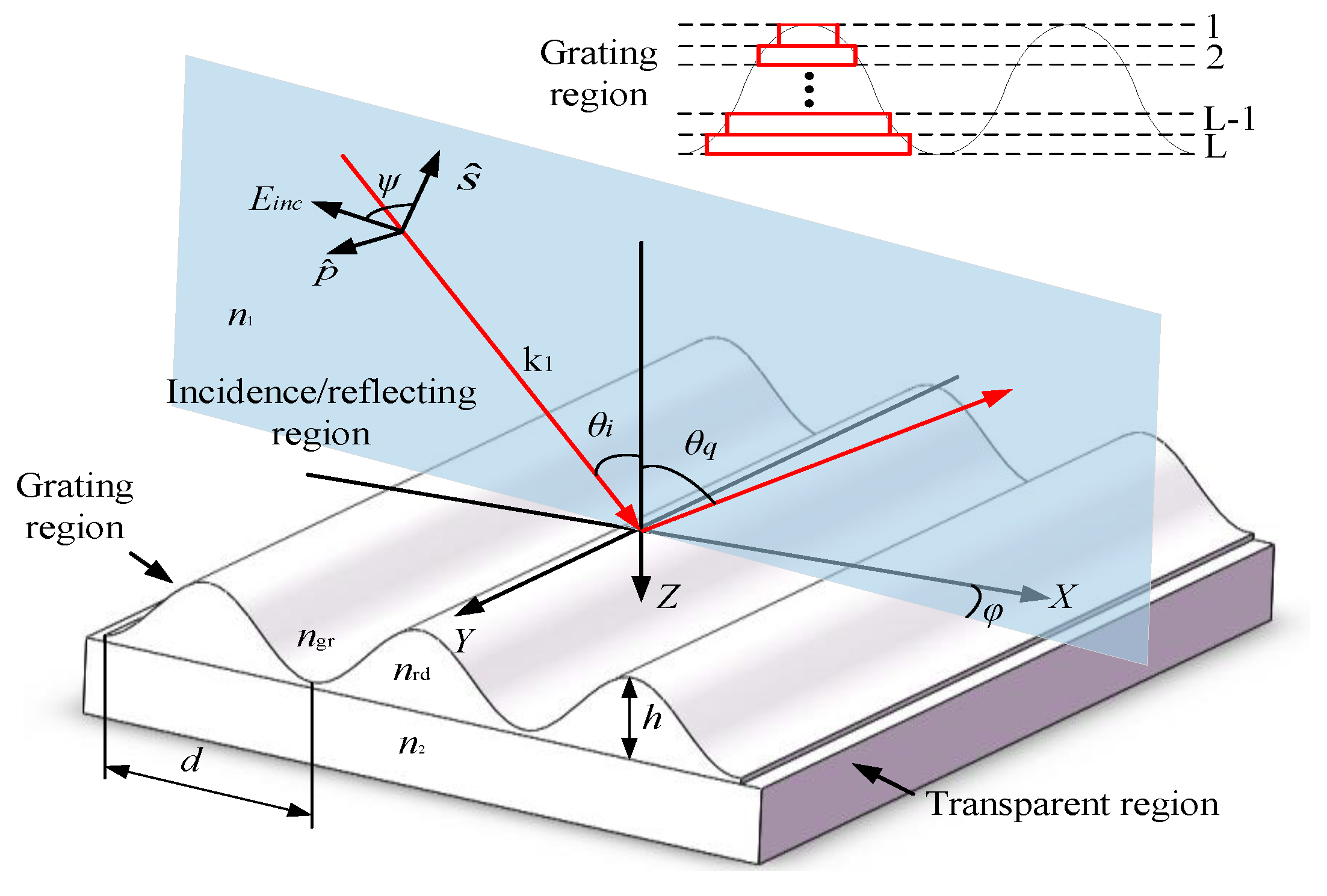
Figure 3 shows a schematic diagram of the Cr grating diffraction, in which
d,
θi,
θq,
m,
λ,
h,
φ,
ψ represent the grating period, incident angle, angle of diffraction, diffraction order, incident wavelength, grating groove depth, angle between the incident plane and the
XZ plane, and angle between the incident plane and the direction of the electric field, respectively. The grating structure is divided into the incident/reflective region, grating region, and transmission region. The refractive indices of the incident/reflective region and transmission region are
n1 and
n2, respectively, and the refractive indices of the grating region are a periodic distribution of the medium represented by
ngr and
nrd.
When the incident beam is incident on the grating surface in the TM polarization state, the electric field vector only has components in the
X and
Z directions, the magnetic field vector only has a component in the
Y-direction, and the electromagnetic field component is zero in all other directions. The analysis is similar when the incident beam is incident in the TE polarization state [
10,
11,
12]. In this research, the self-traceable grating region (0 <
z <
h) is rectangularly layered, and the normalized amplitude of the tangential electromagnetic field component in layer
l can be expressed by the eigenvectors and eigenvalues of the layer.
where
Sl,xi and
Ul,yi are the electromagnetic field components of the
lth layer of the grating,
hl is the thickness of the
lth layer of the grating,
ql,m is the eigenvalue of the
lth layer matrix,
wl,m is the corresponding eigenvector, and
Hl is the depth to the
lth grating layer.
Boundary conditions are to be satisfied at the junction of the incident/transmission region and the grating region and at the junction of the grating region and the transmission region. Moreover, the reflection coefficient R and the transmission coefficient T are to be solved by means of the coupled boundary condition equations.
The following boundary conditions should be satisfied at the boundary between the first layer of the grating and the incident/reflective region, i.e., at
Z = 0:
On the other hand, the following boundary conditions are required to be satisfied at the boundary between the
l-1th layer of the grating and the lth layer, i.e., at
Z =
Hl−1:
Finally, the following boundary conditions should be fulfilled at the last layer of the grating at the boundary with the transmission region, i.e., at
Z =
Hl:
The all-order reflection efficiency
DEri and the transmission efficiency
DEti in the TM polarization state are obtained as:
3. Analysis
Gsolver is a modeling software developed by Grating Solver Development, a US company, to solve the problem of diffraction efficiency calculation for gratings. It can accurately calculate the diffraction efficiency of different grating structure parameters and incident conditions at various orders. According to the diffraction efficiency model of the Cr grating established above, the grating diffraction efficiencies under different laser incident angles are calculated, and the accuracy of the calculation results is verified by simulation using Gsolver software; furthermore, the theoretical feasibility of the self-programming of the strictly coupled wave theory is verified by simulation using Gsolver software. In this research, we only analyze the effect of laser incidence conditions on the diffraction efficiency, so this parameter is variable and other parameters are fixed [
13].
The initial parameters of the grating are as follows: period d = 212.8 nm, groove depth h = 15 nm, refractive index n1 = ngr = 1, n2 = 5.42141 − 0.25056i, and nrd = 2.05009 − 2.89705i. In addition, the incident parameters and conditions are: incident wavelength λ = 405 nm, angle of incidence θ = 70°, and the incident beam is TM polarization. In this research, the beam is incident on the Cr grating, and there is no +1-order of diffraction, so only the grating −1-order of diffraction efficiency is analyzed.
When the angle between the incident plane and the electric field direction is zero (i.e., when
ψ = 0°), the incident state is TM polarization. However, when
ψ = 90°, the incident state is TE polarization.
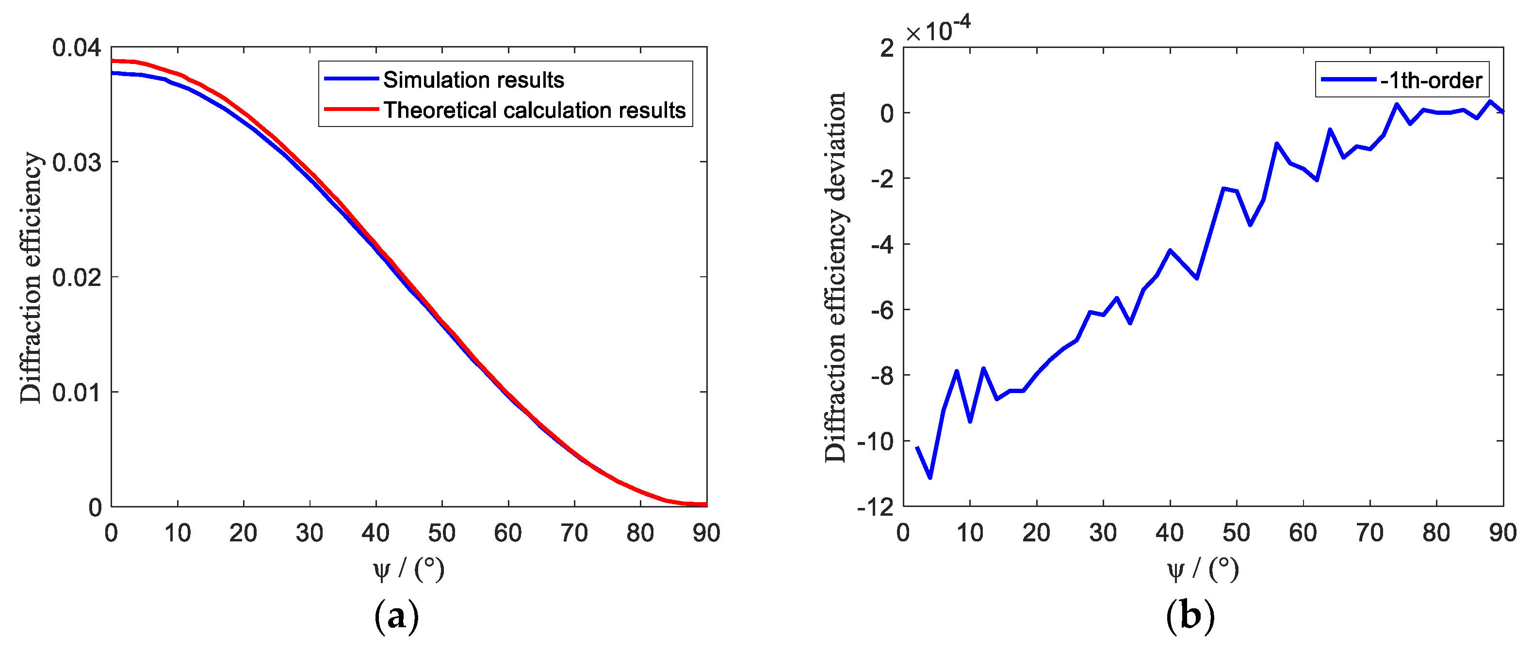
Figure 4 shows the grating −1-order diffraction efficiency when the angle between the incident plane and the electric field direction ranges from 0° to 90°. When the incident state is TM polarization, the −1-order diffraction efficiency of the self-traceable grating is 3.8%. Also, with the increase of the angle between the incident plane and the electric field direction, the grating diffraction efficiency gradually decreases. Note that the diffraction efficiency decreases to zero when the incident state is TE polarization. Hence, in the practical application of self-traceable grating, the utilization rate of the grating diffraction is better when the laser beam is incident in the TM polarization state. Therefore, in the practical application of self-traceable grating, when the beam is incident in the TM polarization state, the grating diffraction utilization can be maximized. It can be seen that the blue line in the figure, i.e., the results calculated according to the strict coupled wave theory, and the red line, i.e., the simulation results of the Gsolver simulation software, are very consistent. We found that the absolute deviation of the two results is only within a range of ±0.0012.
According to the grating equation and the known parameters, it can be calculated that the critical incident angle corresponding to the appearance of −1-order diffraction light from the self-traceable grating is 64.6°. As shown in
Figure 5, when the incident angle ranges from 60° to 64.6°, there is no −1-order diffraction phenomenon in the self-traceable grating, but when the incident angle changes from 64.6° to 67°, the diffraction efficiency rapidly increases to 3.75%. On the other hand, when the incident angle changes from 67° to 80°, the diffraction efficiency is in the steady peak state. Finally, when the incidence angle changes from 80° to 90°, the diffraction efficiency decreases to zero. Therefore, when other parameters are fixed, the incident angle of the beam is controlled in the range of 67°~80°, which can ensure the maximum value of the diffraction efficiency of the self-traceable grating. The absolute deviation between the diffraction efficiency calculated by the coupled wave theory and the result of the simulation is within ±0.0015.
In the precise displacement measurement system based on the self-traceable grating interferometer, the Littrow structure can be used. The distance between the reading head and the grating of this structure does not affect the displacement measurement, so the installation tolerance of the grating and the reading head is large. For the same wavelength of laser light, the Littrow incidence can be used with a higher inscription density of grating, which is conducive to the improvement of the system’s optical resolving power. In addition, this structure can improve the utilization of laser energy [
14], which has a unique advantage in nano-measurement. According to the grating equation, when the laser beam with a wavelength of 405 nm is incident on the surface of the Cr grating at a Littrow angle, the angles of incidence and reflection are both 72.1°. According to
Figure 5a, when the incident angle is 72.1°, the diffraction efficiency of the Cr grating is in the peak state. Therefore, applying Cr grating in the Littrow structure has many advantages in terms of optical path error or laser energy utilization.
4. Experiments and Results
Figure 6 shows the experimental platform built according to the above simulation analysis, which is used to verify the effect of the incident angle on the diffraction efficiency of the self-traceable grating. The experimental system consists of a self-traceable grating with a period of 212.8 nm developed by Tongji University, a laser with a power of 105 mW (ECDL 405 nm, WAVICLE LASER, 100 × 65 × 70 mm
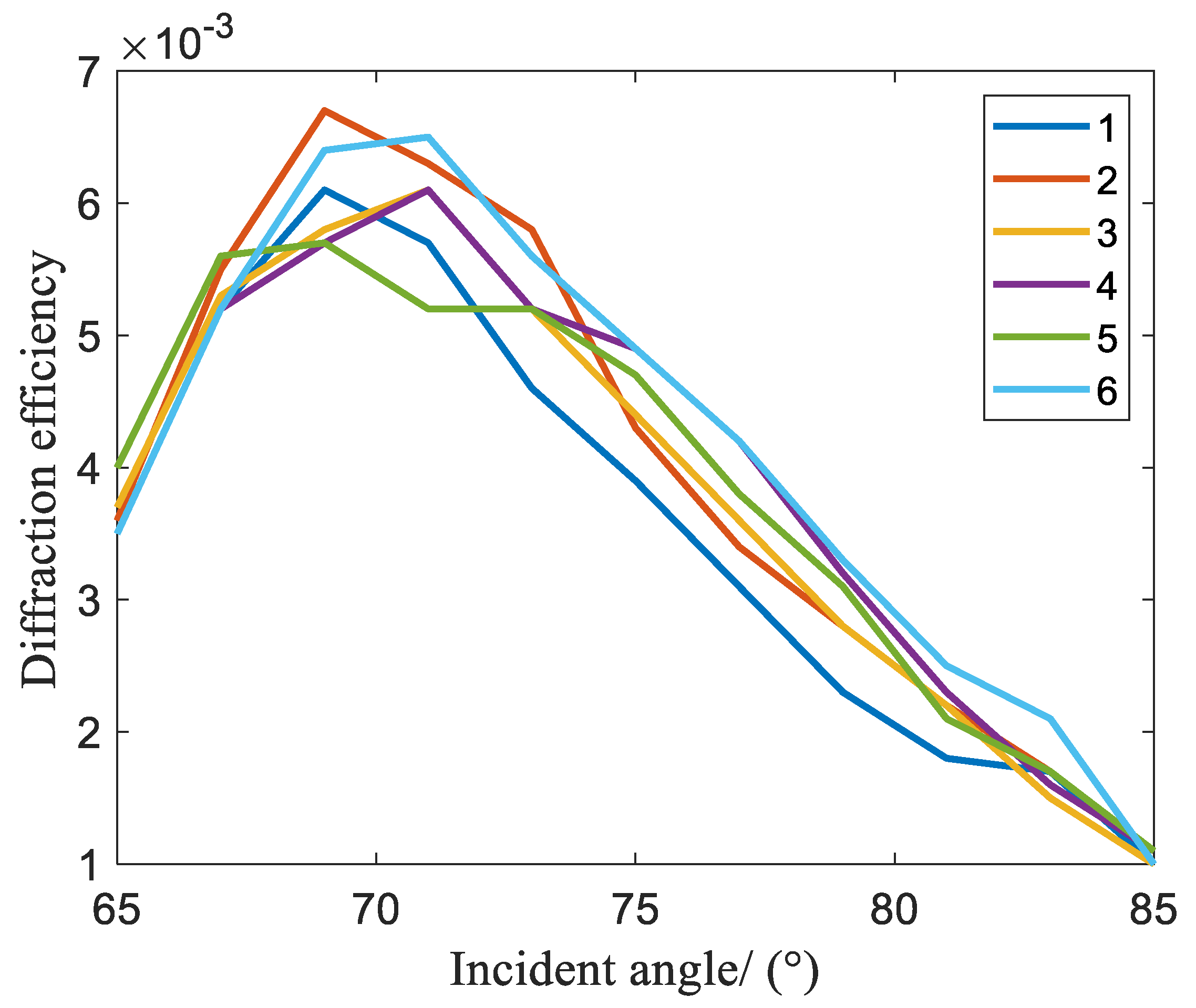
3) and a laser wavelength of 405 nm, a laser collimator (COL), a polarized beam-splitting prism (PBS), a 2 mm aperture stop (AS), a rotary stage (RT), a photodetector (PD) from Thorlabs and an oscilloscope. The PBS is used to split the incident light into TM and TE polarizations based on their polarization states. In the experiment, the laser emits a 405 nm beam, and the emitted light is injected into the PBS through the COL and the 2 mm AS, after which the TM-polarized light is incident on the surface of the self-traceable grating. The RT is controlled to change the incident angle of the laser beam, which ranges from 65° to 85° and is changed by 2° at a time. The PD is used to detect the light intensity
Ii before the beam is incident on the grating and the light intensity
Iq of the −1-order diffraction light after the incident grating, and the −1-order diffraction efficiency of the self-traceable grating is obtained by
Iq/
Ii × 100%. The experimental results are shown in
Table 1.
In
Table 1, the absolute deviation is the difference between the actual measurement results corresponding to the angle in
Figure 6 and the theoretical results corresponding to the angle in
Figure 5. Comparing
Figure 5 and
Figure 7, it can be seen that the trend of the diffraction efficiency of the actually measured self-traceable grating is roughly the same as that of the theoretical calculation, but it is lower than the theoretically calculated value. Note that when the incident angle is about 70°, the actual diffraction efficiency of the self-traceable grating is at the maximum. After that, as the incident angle increases, the diffraction efficiency continues to decay.
The overall results indicate that the actually measured diffraction efficiency is lower than the theoretical value, and the main reasons are as follows:
- (1)
In practice, during the fabrication process of the grating, factors such as an uneven standing wave field, insufficient atomic collimation, and substrate edge diffraction can affect the atomic lithography deposition conditions, resulting in a grating structure that is not an ideal sinusoidal structure [
15].
- (2)
The manufacturing size in the fabrication process of self-traceable grating limits the diffraction efficiency. Compared to ordinary gratings, self-traceable gratings have a smaller dimension, typically 1 mm × 3.0 mm. This size limitation poses a challenge because it may result in the laser beam not fully illuminating the grating surface. When the laser beam is obliquely incident, it can produce a shadowing effect on the self-traceable grating, thereby reducing diffraction efficiency [
14].
- (3)
The roughness of the groove in the self-traceable grating causes chaotic diffuse reflection of some diffracted light, affecting diffraction efficiency. Furthermore, since the self-traceable grating is exposed to the atmospheric environment, it is susceptible to impurities in the air (such as dust), which further affects its roughness and reduces diffraction efficiency [
14,
16].
- (4)
During the measurement of diffraction efficiency, factors such as the instability of the light source, imperfections in the receiver, and alignment errors between the light source and receiver can all contribute to reduced actual measurement results.
The actual structural characteristics of self-traceable grating are the main factor affecting grating diffraction efficiency. However, currently, we do not have the necessary conditions to fabricate self-traceable grating with more perfect structures. In the future, our team will investigate the fabrication of self-traceable grating, quantitatively analyze reasons that may arise during the atomic lithography fabrication technology process that can lead to low grating diffraction efficiency, optimize the fabrication process of self-traceable grating, increase the grating size, and fabricate grating with a good surface structure, thereby improving both the theoretical and practical diffraction efficiency of grating.
5. Conclusions
This research analyzed the length traceability of Cr gratings and important effects in the nanometer measurement traceability system. By establishing a rigorous coupled-wave model for self-traceable Cr grating and obtaining the exact solutions of Maxwell’s equations, which satisfy the electromagnetic field boundary conditions when the laser beam is incident on self-traceable grating, we analyzed the impact of the incident angle on the diffraction efficiency of grating. By measuring and studying the diffraction efficiency of self-traceable Cr gratings, we provided an important basis for grating fabrication and application. In the practical application of a self-traceable grating, it is necessary to combine the influence of the incident angle on diffraction efficiency and the characteristics and advantages of the Littrow structure to select the optimal incident parameters to maximize the diffraction efficiency. In the future, we will analyze the diffraction efficiency of self-traceable Cr gratings based on the fabrication technology of self-traceable gratings. We plan to investigate the factors influencing the structural parameters of self-traceable Cr gratings during the fabrication process. By combining this analysis with the diffraction efficiency study presented in this paper, we aim to fabricate a self-traceable grating with maximum diffraction efficiency.
Author Contributions
Conceptualization, L.L. (Lihua Lei); methodology, L.L. (Lihua Lei) and L.L. (Lijie Liang); software, L.L. (Lihua Lei) and L.L. (Lijie Liang); validation, L.L. (Liqin Liu), Y.G. and Y.Z.; formal analysis, L.L. (Liqin Liu); investigation, C.G.; resources, L.L. (Lihua Lei); data curation, L.L. (Lihua Lei); writing—original draft preparation, Y.S.; writing—review and editing, W.Z. and L.L. (Lijie Liang); visualization, Y.G.; supervision, Y.F.; project administration, Y.F.; funding acquisition, Y.S. and L.L. (Lihua Lei). All authors have read and agreed to the published version of the manuscript.
Funding
This research was Sponsored by Shanghai Natural Science Foundation [Grant No. 21ZR1483100], and Program of Shanghai Academic/Technology Research Leader [Grant No. 21XD1425000].
Institutional Review Board Statement
Not applicable.
Informed Consent Statement
Not applicable.
Data Availability Statement
Data are contained within the article.
Conflicts of Interest
The authors declare no conflicts of interest.
References
- Deng, X.; Li, T.B.; Cheng, X.B. Self-traceable grating reference material and application. Opt. Precis. Eng. 2022, 30, 2608–2625. [Google Scholar]
- Downs, M.; Birch, K. Bi-directional fringe counting interference refractometer. Precis. Eng. 1983, 5, 105–110. [Google Scholar] [CrossRef]
- Chu, X.Y.; Shen, Y.Q.; Liu, L.Q.; Zou, W.Z.; Guan, Y.Q.; Guo, C.W.; Zhang, Y.J.; Liang, L.J.; Kong, M.; Lei, L.H. Research on fine characterization technology of key parameters of linewidth of Si/SiO2 Multilayer Film. Infrared Laser Eng. 2023, 53, 20230475-1–20230475-11. [Google Scholar]
- Chen, K.Q.; Guan, Y.Q.; Zou, W.Z.; Deng, X.; Kong, M.; Chen, Y.Q.; Xiong, Y.F.; Fu, Y.X.; Lei, L.H. Research on the method of nanometer grating spacing comparison measurement based on Cr atomic lithography technology. Acta Metrol. Sin. 2023, 44, 671–678. [Google Scholar]
- Wu, Z.R.; Xiong, Y.F.; Lei, L.H.; Tan, W.; Tang, Z.H.; Deng, X.; Cheng, X.B.; Li, T.B. Sub-5 nm AFM Tip Characterizer Based on Multilayer Deposition Technology. Photonics 2022, 9, 665. [Google Scholar] [CrossRef]
- Deng, X.; Dai, G.; Liu, J. A new type of nanoscale reference grating manufactured by combined laser-focused atomic deposition and x-ray interference lithography and its use for calibrating a scanning electron microscope. Ultramicroscopy 2021, 226, 113293. [Google Scholar] [CrossRef] [PubMed]
- Lin, Z.C.; Yao, Y.L.; Xie, Z.N.; Xue, D.B.; Zhou, T.; Tang, Z.H.; Lei, L.H.; Jin, T.; Dun, X.; Deng, X.; et al. Chromium Self-Traceable Length Standard: Investigating Geometry and Diffraction for Length Traceability Chain. arXiv 2023, arXiv:2306.14083. [Google Scholar]
- McClelland, J.J.; Scholten, R.E.; Palm, E.C.; Celotta, R.J. Laser-focused atomic deposition. Science 1993, 262, 877–880. [Google Scholar] [CrossRef] [PubMed]
- McClelland, J.; Anderson, W.; Bradley, C.; Walkiewicz, M.; Celotta, R.; Jurdik, E.; Deslattes, R. Accuracy of nanoscale pitch standards fabricated by laser-focused atomic deposition. J. Res. Natl. Inst. Stand. Technol. 2003, 108, 99–114. [Google Scholar] [CrossRef] [PubMed]
- Shang, P. Study on the Key Technology of High-resolution Diffraction Grating Interferometric Transducer of Linear Displacements; Hefei University of Technology: Hefei, China, 2012. [Google Scholar]
- Afshar, B.A.; Soltanpour, P.; Sabatyan, A. Comprehensive analysis of diffraction efficiency of conical beam from sub-wavelength binary metallic grating using rigorous coupled-wave theory. Opt. Int. J. Light Electron Opt. 2015, 126, 5504–5508. [Google Scholar] [CrossRef]
- Li, J.; Wang, J.-B.; Sun, Z.; Shi, L.-H.; Ma, Y.; Zhang, Q.; Fu, S.-C.; Liu, Y.-C.; Ran, Y.-Z. Efficient Rigorous Coupled-Wave Analysis Without Solving Eigenvalues for Analyzing One-Dimensional Ultrathin Periodic Structures. IEEE Access 2020, 8, 198131–198138. [Google Scholar] [CrossRef]
- Yang, G.H.; Wang, Y.; Li, J. Diffraction efficiency of enhanced phase grating. Acta Opt. Sin. 2021, 41, 39–50. [Google Scholar]
- Yang, L.L. Measurement of diffraction efficiency for diffractive optical elements with oblique incidence. Infrared Laser Eng. 2018, 47, 117003. [Google Scholar] [CrossRef]
- Deng, X.; Li, T.B.; Lei, L.H.; Ma, Y.; Ma, R.; Weng, J.J.; Li, Y. Fabrication and measurement of traceable pitch standard with a big area at trans-scale. Chin. Phys. B 2014, 23, 090601. [Google Scholar] [CrossRef]
- Luo, J.Y.; Guo, Z.H.; Huang, H. Synchrotron radiation research on diffraction efficiency of multilayer coated grating. Acta Opt. Sin. 2021, 41, 1405001. [Google Scholar]
| Disclaimer/Publisher’s Note: The statements, opinions and data contained in all publications are solely those of the individual author(s) and contributor(s) and not of MDPI and/or the editor(s). MDPI and/or the editor(s) disclaim responsibility for any injury to people or property resulting from any ideas, methods, instructions or products referred to in the content. |
© 2024 by the authors. Licensee MDPI, Basel, Switzerland. This article is an open access article distributed under the terms and conditions of the Creative Commons Attribution (CC BY) license (https://creativecommons.org/licenses/by/4.0/).


