1. Introduction
High-order transverse-mode lasers in optical fibers offer a means by which to extend the spatial dimension of information through mode multiplexing [
1,
2,
3]. Mode group diversity multiplexing enables the transcending of the transmission capacity bottleneck inherent in existing single-mode fiber (SMF) communication systems, effectively catering to the rapidly escalating demands for bandwidth [
4]. Moreover, high-order transverse-mode lasers hold vast potential applications in various domains such as optical fiber tweezers [
5], high-resolution imaging [
6,
7], high-dimensional quantum entanglement [
8], and optical micromachining [
9,
10]. Consequently, the controllable excitation of high-order transverse-mode lasers in an all-fiber system has become a focal point of research in recent years [
11,
12]. However, there is still no mature optical fiber device that allows fiber laser systems to stably generate high-order transverse-mode lasers.
Currently, the primary approach for generating high-order transverse modes stably within fibers is to integrate mode-selective devices. The devices include options such as few-mode fiber gratings [
13,
14,
15], asymmetric fiber couplers [
16,
17,
18], and misalignment fiber structures [
19,
20]. The few-mode fiber grating method, however, is constrained by the precision of both the grating and the filter, limiting its capacity to produce only the initial few high-order transverse-mode laser outputs. Additionally, it requires meticulous control over the input laser’s wavelength. On the other hand, schemes based on couplers necessitate the iterative design and fabrication of mode-selective fiber couplers tailored to the desired modes. The cascading of multiple couplers results in a complex system with increased transmission losses. The fiber misalignment fusion method represents the simplest mode conversion technique, yet it incurs significant insertion losses and exhibits exceedingly low mode conversion efficiency.
Photonic lanterns are frequently utilized in optical transmission systems and optical networks, typically to enhance the light reception or transmission capabilities of a system [
21,
22,
23]. In addition, the photonic lantern is also an excellent mode division multiplexing device, which can convert the fundamental mode into multiple higher-order modes [
24,
25,
26]. However, due to the lack of effective system connection solutions, there are very few reports on combining photonic lanterns with fiber lasers to generate high-order transverse modes. To address the limitations associated with controllable high-order transverse modes within fiber laser systems, a collaborative effort of researchers from multiple institutions introduced a photonic lantern (PL)-based approach for generating high-order transverse-mode lasers [
27]. The incorporation of photonic lanterns into fiber lasers to achieve multiple high-order transverse-mode outputs represents a significant and purposeful endeavor. However, in this scheme, the photonic lantern primarily serves as a mode conversion element. The incorporation of Bragg fiber gratings and Fresnel reflection from fiber-end facets is still required to establish a linear laser resonator.
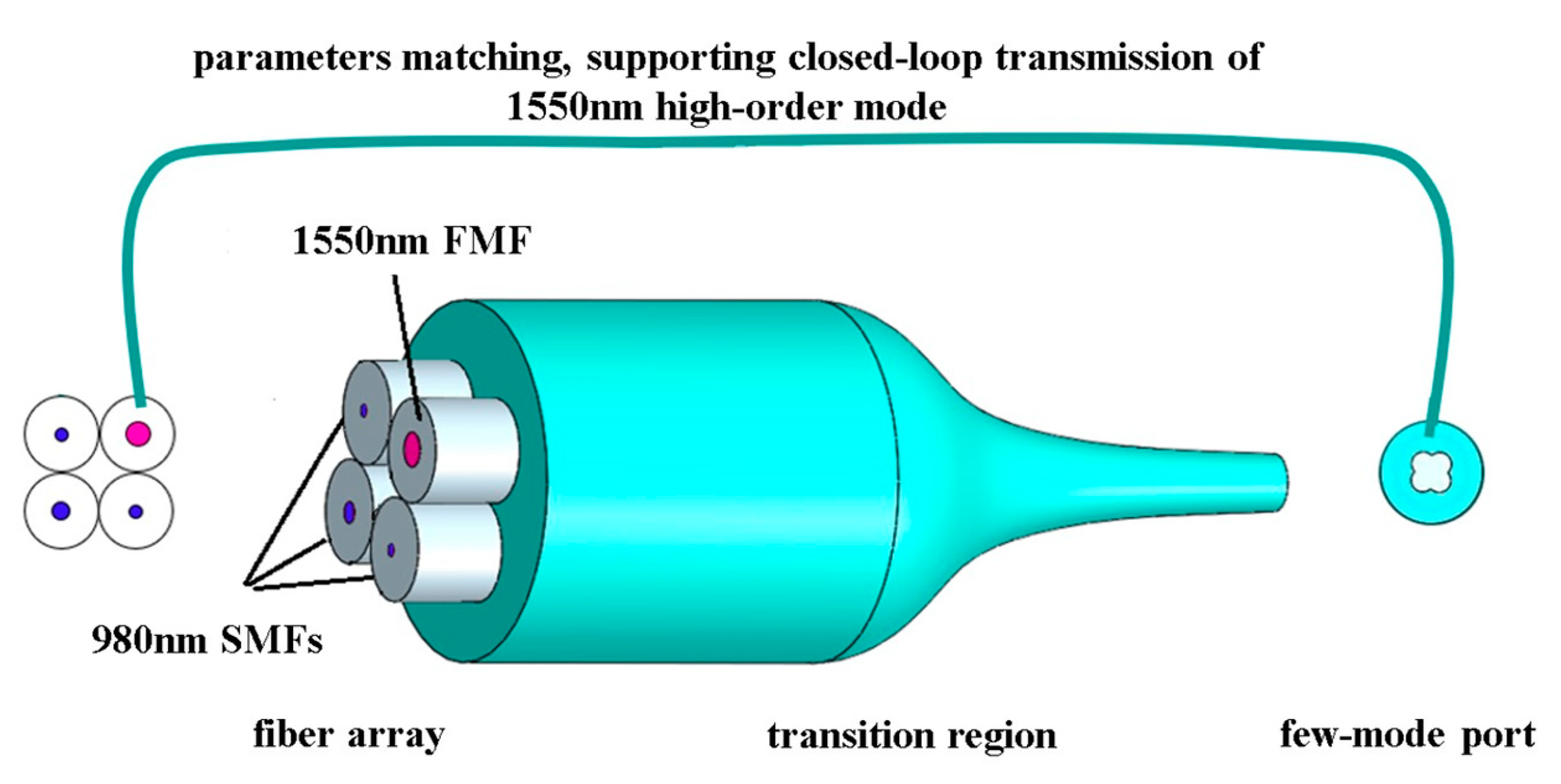
In this paper, to address the challenges of generating and transmitting high-order modes in fiber lasers, we designed a self-matching photonic lantern (SMPL). To achieve selective generation, oscillation, and output of multiple high-order transverse-mode lasers within a few-mode fiber (FMF) cavity, the SMPL needs to possess three essential characteristics: (i) dual-band multiplexing at 980/1550 nm; (ii) mode selection at 980 nm wavelength; and (iii) self-contained cavity behavior of the FMF at 1550 nm wavelength. To realize these functionalities and solve the problem of effective connection between photon lanterns and fiber lasers, a uniquely structured SMPL is designed. Unlike traditional photon lanterns, the SMPL introduces an FMF into the single-mode array, allowing the FMF to pair with the few-mode port of the SMPL to form a fiber ring. The proposed SMPL is tailored for 1550 nm fiber ring lasers, thus offering dual-band multiplexing capability at 980/1550 nm. Via SMFs for mode selection, 980 nm pump light is selectively excited, and 1550 nm light can be efficiently transmitted from the FMF to the few-mode port channel with the mode profiles preserved.
3. Simulation and Analysis
For the SMPL characterized by the aforementioned features, we conducted modeling and simulation validation. First, considering the selective excitation of 980 nm high-order transverse modes, the 980 nm light is injected from different SMFs, after passing through the SMPL, three high transverse modes (LP01, LP11a, and LP11b) are generated at the few-mode port, respectively. According to the design principles of the mode-selective PL [
28], the fiber array should encompass dissimilar 980 nm SMFs. Notably, two of these fibers possess identical core diameters corresponding to two sets of LP11 modes, while the remaining SMF possesses a larger core diameter, corresponding to the LP01 mode. Second, considering the closed-loop transmission of 1550 nm high-order transverse modes, the modes in the 1550 nm FMF should be able to keep the mode profile unchanged after the evolution in the SMPL.
What is more, the parameters of the few-mode port formed by tapering should be matched with that of the FMF, and the two connect to form a resonant ring which can be used for the closed-loop transmission of high-order transverse modes.
Assume that the numerical aperture of the 980 nm SMF in the SMPL is 0.12, and the numerical aperture of the 1550 nm FMF and the FMF port are both 0.1. According to the numerical aperture calculation formula of the weak guiding fiber
NA = (
nco2 −
ncl2)
1/2, where
nco is the RI of the fiber core and
ncl is the RI of the fiber cladding, when the RI of the outermost capillary of the PL is 1.4400, the refractive indices of the core and cladding in the 980 nm SMFs are 1.4485 and 1.4435, respectively. Similarly, it can be calculated that the refractive indices of the core and cladding of the 1550 nm FMF are 1.4469 and 1.4435, respectively. The RI distribution at the fiber array end face of the SMPL is shown in
Figure 2a.
In the formation process of the photonic lantern, the claddings of individual fibers at the input end of the fiber array are tangential and arranged in a manner similar to that in
Figure 2a. As the taper ratio decreases, the fibers melt and become thinner, undergoing mutual compression and fusion. Therefore, in our simulation modeling, we set the initial end face structure of the SMPL, as depicted in
Figure 2b, with overlapping between several fibers. Based on the structure depicted in
Figure 2b, finite element analysis (FEA) is employed to simulate and analyze the mode evolution process of the SMPL. Key simulations parameters include the structural model, refractive indices of different regions, scanning size, mesh partitioning, and dimensions of different fibers.
The initial outer diameter of the photonic lantern could be set according to the typical fiber claddings; in our case, the cross-section is determined to be 350 μm, with a simulated decrement size of 5 μm. To simulate the entire tapering process, the minimum simulated size of the photonic lantern cross-section is set to 10 μm. This minimum size is well below the dimensions matched with the few-mode fiber at 1550 nm, ensuring that the simulation process fully encompasses the entire tapering process, covering reasonable dimensions of the few-mode port. Given that the simulation structure comprises 13 domains, 48 boundaries, and 41 vertices, with extremely small regions necessitating highly refined meshes which consume substantial computational memory and time, an adaptive mesh partitioning strategy, as shown in
Figure 2c, was employed, resulting in a total mesh containing 12,090 domain elements and 688 boundary elements.
Based on the RI parameters of the fibers depicted in
Figure 2a, to determine the fiber core sizes that meet the requirements, calculations were performed for the mode-effective RI at wavelengths of 980 nm and 1550 nm within varying fiber core diameters. In
Figure 3a, with a simulation wavelength of 980 nm, it can be seen that the fiber only supports stable transmission of the LP
01 mode within the core diameter range of 2 μm to 6 μm. If the core diameter exceeds 6 μm, then other modes (represented by the blue curves in the graph) will appear within the core. Higher mode-effective RI is associated with larger core diameters; this characteristic remains even after adiabatic tapering. Therefore, in our simulations, we chose core diameters of 4 μm, 4 μm, and 6 μm for the 980 nm SMFs, corresponding to the excitation of LP
11a, LP
11b, and LP
01 modes at the few-mode port of the SMPL. In
Figure 3b, with a simulation wavelength of 1550 nm, a core diameter within the range of 12 μm to 19 μm supports the stable transmission of three linearly polarized modes: LP
01, LP
11a, and LP
11b. LP
11a and LP
11b modes share identical effective refractive indices, indicating the same propagation constant, thus forming a degenerate mode pair.
Based on the research conclusions regarding the influence of fiber geometric arrangement on mode-selective excitation within the PL, for a PL supporting the propagation and conversion of LP
mn modes (where
m represents the radial mode order and
n represents the azimuthal mode order), the fiber array should be arranged in
m concentric circles [
29].
The number of fibers on each circular ring should be N = 2nmax + 1, thereby breaking mode degeneracy and achieving selective excitation of modes within the PL. In the case of a PL accommodating LP01, LP11a, and LP11b modes, m = 1, nmax = 1, and N = 3, requiring the distribution of three 980 nm SMFs on a single circular ring. Furthermore, considering the inclusion of FMF for transmitting the 1550 nm light as part of the PL, without injecting 980 nm light itself, it is feasible to arrange the four fibers evenly along a circular configuration.
To investigate how individual modes within the dispersive fiber of the SMPL transform into orthogonal modes within the few-mode port, an analysis was conducted on various cross-sections within the transition region of the SMPL. This involved discretized modeling along the axial direction of the SMPL.
It is assumed that the claddings of the optical fibers in the transition region of the SMPL have been fused with each other, and there is no gap between the fibers or between the fibers and the capillary. During the tapering process, the size of the capillary and the fiber bundle shrinks in proportion.
Injecting 980 nm light into the 980 nm SMFs of the input fiber array,
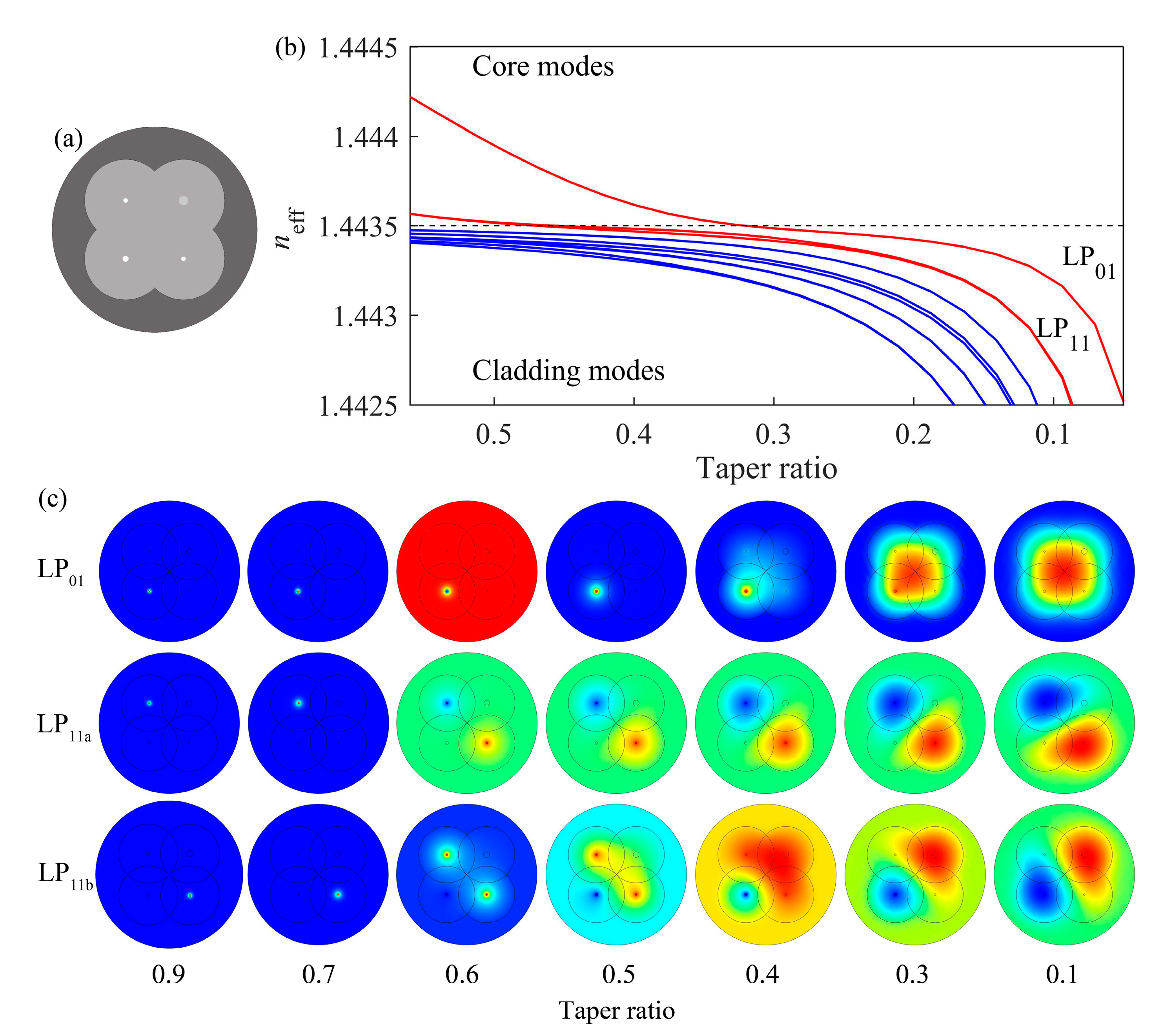
Figure 4 illustrates the variations in an effective refractive index and mode field as the taper ratio changes. The taper ratio is defined as the ratio of the diameter of the tapered section to the diameter before tapering [
30]. In
Figure 4a, a schematic of the cross-section of the SMPL’s transition region is shown. The highlighted dots represent the three tapered 980 nm SMF cores, with the upper-left and lower-right cores having the same size (4 μm), in which the 980 nm fundamental mode will correspondingly evolve into LP
11a and LP
11b modes, while the thicker core in the lower-left corner (6 μm) will finally evolve into the LP
01 mode.
Figure 4b illustrates the mode-effective refractive indexes against the taper ratio. Due to the varying core diameters of the SMFs, the mode-effective refractive indexes also differ. Larger core diameters correspond to higher effective refractive indices [
28]. The horizontal dashed line indicates the fiber cladding RI. With the taper ratio decreasing, the fundamental modes of the 980 nm SMFs show a decrease in modal effective indexes. When the taper ratio is larger than 0.4, the mode-effective indexes are higher than those of the cladding (red curves). The 980 nm light exists in the SMF cores in the form of the fundamental modes. As the taper ratio further decreases, the core diameter shrinks accordingly. When the refractive indexes are reduced to below the dashed line, the SMFs fail to confine modes within the cores. The light is then leaked into the cladding, which becomes the new FMF core. Along the transition to smaller taper ratio, light within the two smaller-sized fiber cores first escapes from the cores and then gradually evolves into the LP
11a and LP
11b modes at the few-mode port. In the case of the larger SMF core, light spreads out of the core approximately at a taper ratio of 0.3, progressively evolving into the LP
01 mode at the few-mode port.
Figure 4c shows the evolution of modes throughout the tapered transition. From the first row in
Figure 4c, it can be observed that the LP
01 mode of the 980 nm SMF located in the lower-left corner gradually leaks into the cladding as the taper ratio decreases. When the taper ratio reaches 0.1, a new LP
01 mode forms at the few-mode port. In the second and third rows, the LP
01 modes injected into the other two 980 nm SMFs undergo a progressive evolution into LP
11a and LP
11b modes as the taper ratio decreases. Simulation results in
Figure 4 confirm that at a taper ratio of 0.1, the SMPL can achieve selective excitation of the three sets of transverse modes at 980 nm. It is worth noting that the simulations only limit the taper ratio; that is, the diameter of the taper area is constrained. The specific taper length can be controlled according to the adiabatic taper requirements to satisfy the lossless coupling of light between SMFs to specific modes of the few-mode port.
To validate the mode transmitting characteristic between the input FMF and the output few-mode port of the SMPL at a wavelength of 1550 nm, simulations were conducted. Based on the simulation results shown in
Figure 3, the core diameter of the 1550 nm FMF was set to 15 μm, with an RI of 1.4469.
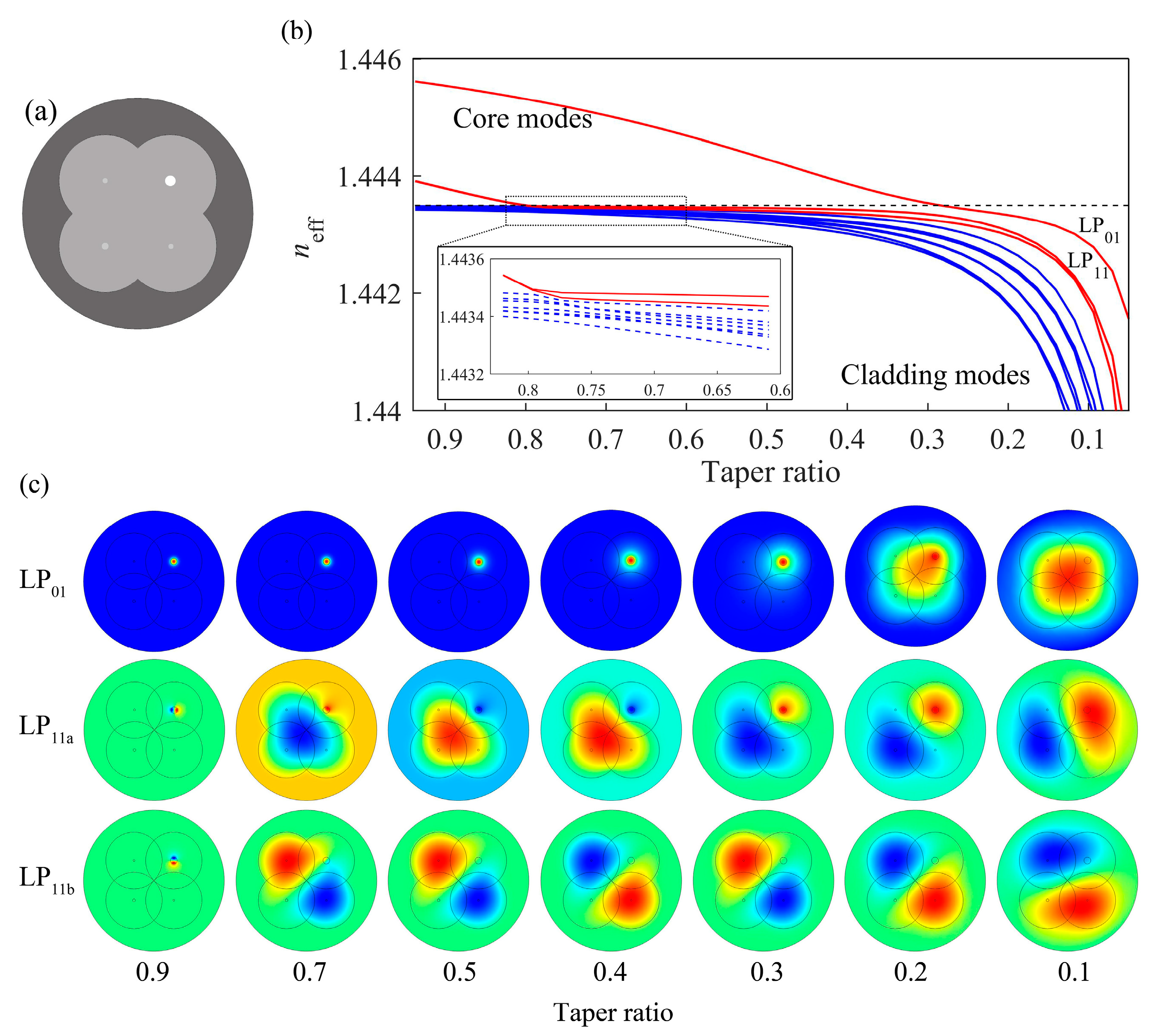
Figure 5 shows how the mode transmission characteristics of the 1550 nm light wave changes with the taper ratio after it is injected from the FMF of the input fiber array.
Figure 5a depicts a cross-section schematic of the transition region of the SMPL, with the highlighted dot representing the tapered 1550 nm FMF core.
Figure 5b illustrates the mode-effective indexes against the taper ratio, with the SMPL operating at 1550 nm. When the taper ratio is larger than 0.9, the 1550 nm FMF is capable of stably restricting and propagating both LP
01 and LP
11 modes. As the taper ratio decreases, the FMF cores become less confined, and the modes start to couple to the claddings, which form the new core of the FMF port.
Figure 5c illustrates the evolution of modal profiles within the SMPL as a function of the taper ratio. In the first row, the LP
01 mode injected from the 1550 nm FMF gradually spread out of the core as the taper ratio decreases. It eventually evolves into a new LP
01 mode at the few-mode port. When the taper ratio reaches 0.1, the LP
01 mode’s optical field is uniformly distributed at the few-mode port, achieving LP
01 mode field matching with the initial FMF. In the second and third rows, the other two modes within the 1550 nm FMF, namely, the LP
11a and LP
11b modes, also evolve to form new LP
11 modes at the few-mode port as the taper ratio decreases. This enables LP
11a and LP
11b mode field matching with the initial FMF, respectively. Through the simulation results, it is evident that different modes within the 1550 nm FMF, after evolving through the SMPL, can maintain their modal characteristics. In the few-mode port, the new fiber core evolves from the cladding of the original fiber array. If fibers with outer diameters of 125 μm are used in the fiber array, when the taper ratio is 0.1, the size of the few-mode core in the tapered end will be approximately a dozen micrometers, which matches well with the core of the FMF in the input array. By adjusting the wall thickness of the glass tube, the outer diameter of the tapered few-mode port can also be aligned with the outer diameter of the FMF after tapering. Connecting the FMF to the few-mode port enables the low-loss closed-loop propagation of higher-order transverse modes at 1550 nm.
To verify the feasibility of the proposed SMPL, preliminary experiments were conducted.
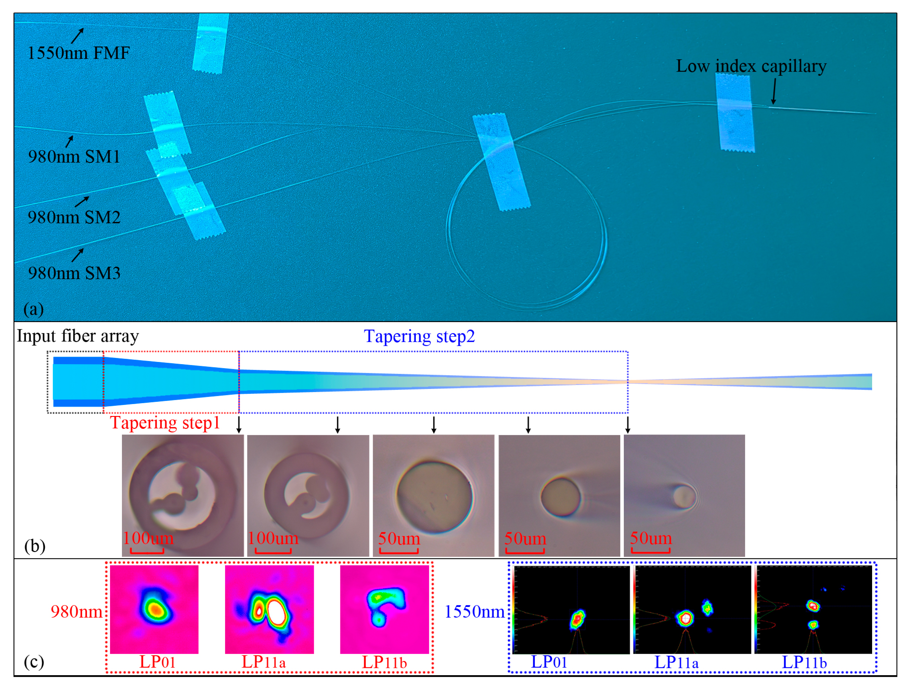
Figure 6a shows the fabricated SMPL component, with the left side being the input fiber array and the right side being the few-mode port. The input fiber array consists of one 1550 nm FMF and three 980 nm SMFs. The original core diameter of 980 nm SMF is about 5 μm. To excite the LP11 modes, two of the SMFs underwent pre-tapering, resulting in a cladding diameter of about 97.2 μm and a core diameter of 3.8 μm. Four input fibers, with their coatings removed, were inserted into a low-index capillary and underwent two-step tapering to form the SMPL.
Figure 6b provides a schematic of the SMPL tapering process and cross-sectional views of different taper regions. The parameters for the first tapering step included a tapering speed of 200 μm/s, a stretching length of 15 mm, and a fire head with a reciprocating motion at a speed of 6 mm/s. For the second tapering step, the tapering speed decreased to 100 μm/s, and the stretching length was 45 mm. The outer diameters of the SMPL cross-sections are 286.4 μm, 229.2 μm, 95.6 μm, 49.5 μm, and 28.7 μm, respectively. Due to the pre-tapering of the 980 nm SMFs and assembly tolerances, there was initially a gap between the fiber array and the low refractive index sleeve at the beginning of the tapering process. As tapering proceeded, the gap gradually decreased and eventually disappeared.
Subsequently, we conducted tests on the mode transmission characteristics of the SMPL.
Figure 6c presents the mode field patterns of 980 nm and 1550 nm lasers after transmission through the SMPL. The 980 nm lasers were, respectively, injected into different 980 nm SMFs, and LP01, LP11a, and LP11b modes were detected at the SMPL’s few-mode port, as illustrated in the red dashed box in
Figure 6c. By employing fiber misalignment fusion and polarization control, 1550 nm higher-order modes were excited and then transmitted through the SMPL. The LP01, LP11a, and LP11b modes at 1550 nm were sequential observed at the few-mode end, as depicted in the blue dashed box in
Figure 6c.
The experimental results are consistent with simulations, thereby confirming the feasibility of the SMPL. In brief, through delicate structural design, the SMPL could realize mode-selective excitation at 980 nm and mode preservation at 1550 nm. When applied to a 1550 nm fiber ring laser, pump light could be injected through different 980 nm SMFs of the SMPL. This enables the selective excitation of multiple high-order transverse modes at the few-mode port, endowing it with mode selection capabilities at 980 nm. Once the 980 nm pump light is amplified and converted into a 1550 nm laser within the laser system, the 1550 nm laser can maintain its mode characteristics and achieve low-loss transmission through the FMF (transition region) few-mode port of the SMPL. Connecting the FMF to the few-mode port of the SMPL establishes a ring resonator, enabling the oscillation and transmission of high-order mode lasers within it. Therefore, the SMPL incorporates dual-band multiplexing capabilities at 980/1550 nm, rendering it a substitute for wavelength-division multiplexers and a direct component for constructing ring resonator fiber laser systems.


