Review

Applications of Microstructured Optical Fibers in Ultrafast Optics: A Review

by
Ziwen Tang
1,2,
Zihua Zheng
1,
Boyao Li
1,3,
Zhiyi Wei
3,4,5 and
Jinghua Sun
1,3,*
1
Institute of Ultrafast Optics and Photonics, Dongguan University of Technology, Dongguan 523808, China
2
Guangdong Provincial Key Laboratory of Nanophotonic Functional Materials and Devices, South China Normal University, Guangzhou 510006, China
3
Quantum Science Center of Guangdong-HongKong-Macao Greater Bay Area, Shenzhen-Hong Kong International Science and Technology Park, No. 3 Binglang Road, Futian District, Shenzhen 518045, China
4
Beijing National Laboratory for Condensed Matter Physics, Institute of Physics, Chinese Academy of Sciences, Beijing 100190, China
5
Songshan Lake Materials Laboratory, Dongguan 523808, China
*
Author to whom correspondence should be addressed.
Photonics 2024, 11(2), 151; https://doi.org/10.3390/photonics11020151
Submission received: 31 December 2023 / Revised: 25 January 2024 / Accepted: 3 February 2024 / Published: 5 February 2024

Abstract

:
With the development of laser technology, microstructured optical fibers (MOFs) have become an important part of ultrafast optics, providing excellent platforms for ultrafast laser pulse generation, amplification, and compression, promoting the development of fiber laser systems to generate high power, high pulse energy, and few-cycle duration pulses. MOFs extend the ultrafast laser spectrum to the vacuum ultraviolet (VUV) and even extreme ultraviolet (EUV) regions based on dispersive wave emission and high harmonic generation, as well as to the mid-infrared region based on soliton self-frequency shift (SSFS), contributing compact and low-cost light sources for precision microscopy and spectroscopy. In this paper, first several common types of MOFs are introduced, then the various applications of MOFs in ultrafast optics are discussed, mainly focusing on the aspects of ultrafast laser pulse scaling in pulse energy and spectral bandwidth, and finally the possible prospects of MOFs are given.

1. Introduction

Ultrafast lasers have played key roles in cutting-edge science and technology, bringing revolutionary progress in physical [1,2], biological [3,4], and chemical [5,6] sciences, as well as supplying advanced tools for modern industry. The Nobel Prize of 2023 was awarded to the field of ultrafast lasers for attosecond science. Looking back at the development of ultrafast lasers, the earliest pulsed lasers were on the millisecond scale, and in 1962, McClung et al. utilized Q-switching techniques and reduced the pulse width to the nanosecond scale [7]. With the advent of mode-locking techniques, the duration of the pulses could be reduced to the femtosecond scale, and in 1981, Fork et al. achieved sub-hundred femtosecond pulse output by colliding pulse mode-locking [8]. In 2001, Hentschel et al. used a femtosecond laser interacting with an inert gas to generate high harmonics and obtained a pulse output with a width of 650, which declared that ultrafast science had entered the attosecond stage [9]. This is considered one of the milestones in the history of laser science. In the history of ultrafast lasers, power, spectral width, pulse duration, and other parameters have been continuously measured. It has been able to produce a variety of ultrafast lasers, and microstructured optical fibers (MOFs) are definitely one of the important promoters due to their flexibility in the design of structure, making it possible to customize the dispersion and nonlinearity, while the two factors play a decisive role in ultrafast lasers. Ultrafast lasers generated with MOFs play an influential role in biomedicine [10,11], optical communication [12], precision measurement [13], etc., which has a great impact on either the development of science or people’s lives. MOFs also play important roles in many other fields, such as in sensing devices [14,15,16,17], etc.
In this paper, we first introduce several common MOFs and their working principles by using the light-guiding mechanism as a clue, then present various applications of MOFs in ultrafast optics and briefly review their development, which is mainly focused on the generation and modulation of ultrafast lasers, including amplification, spectrum engineering, pulse compression, etc. Finally, we give the possible future development prospects and outlooks.

2. Types of MOFs

The concept of MOFs may have appeared very early, but they were widely known because of the large scale of their application fields. They started with photonic crystal fiber (PCF), which was proposed by Russell et al. in 1992 [18]. With the continuous improvement of the fiber fabrication process, a variety of new types of fibers are emerging. From evolution to the present stage, MOFs include a very wide range. Broadly speaking, as long as the core structure or cladding structure is microprocessed, which is different from the core-cladding structure of traditional step-refractive index fiber, it can be defined as MOF. According to the mechanism of light guiding, there are total internal reflection MOFs, photonic bandgap MOFs, and hollow anti-resonant MOFs, each of which has a variety of structures, and they rely on these structures that can be flexibly modulated to achieve a rich range of applications in the field of ultrafast optics, which is also where the attraction of MOFs lies. In this section, we will introduce some common MOFs and explain their working principles.

2.1. Total Internal Reflection MOFs

The most classical total internal reflection (TIR) MOFs are solid PCFs (see Figure 1). Although these solid PCFs have different structures—single-core; four-core; or even multi-core—and different structures around the core; they all have a common feature: the core is of high effective refractive index compared to the cladding, and it is following the refractive index guiding mechanism, which is similar to that of conventional fibers, based on the refractive index difference between the core and the cladding to achieve TIR. Therefore, these MOFs are called refractive index guided, or TIR.
Figure 1a shows the earliest PCF of the TIR type [19], where the cladding consists of a precisely designed periodic arrangement of air holes and the fiber is formed by silica material. It is these porous array structures that reduce the effective refractive index of the silica. As a result, cladding with air holes has a lower refractive index compared to an all-silica core. This satisfies the TIR guiding mechanism, restricting light propagation within the fiber core. By modulating the distance between the air holes and the diameter of the air holes, control of the guidance pattern in the fiber core can be achieved. In most cases, single-mode transmission is needed, and the solid-core PCF can realize infinite single-mode [22] and maintain good mode characteristics from ultraviolet (UV) to near-infrared (NIR).

2.2. Photonic Bandgap Fiber

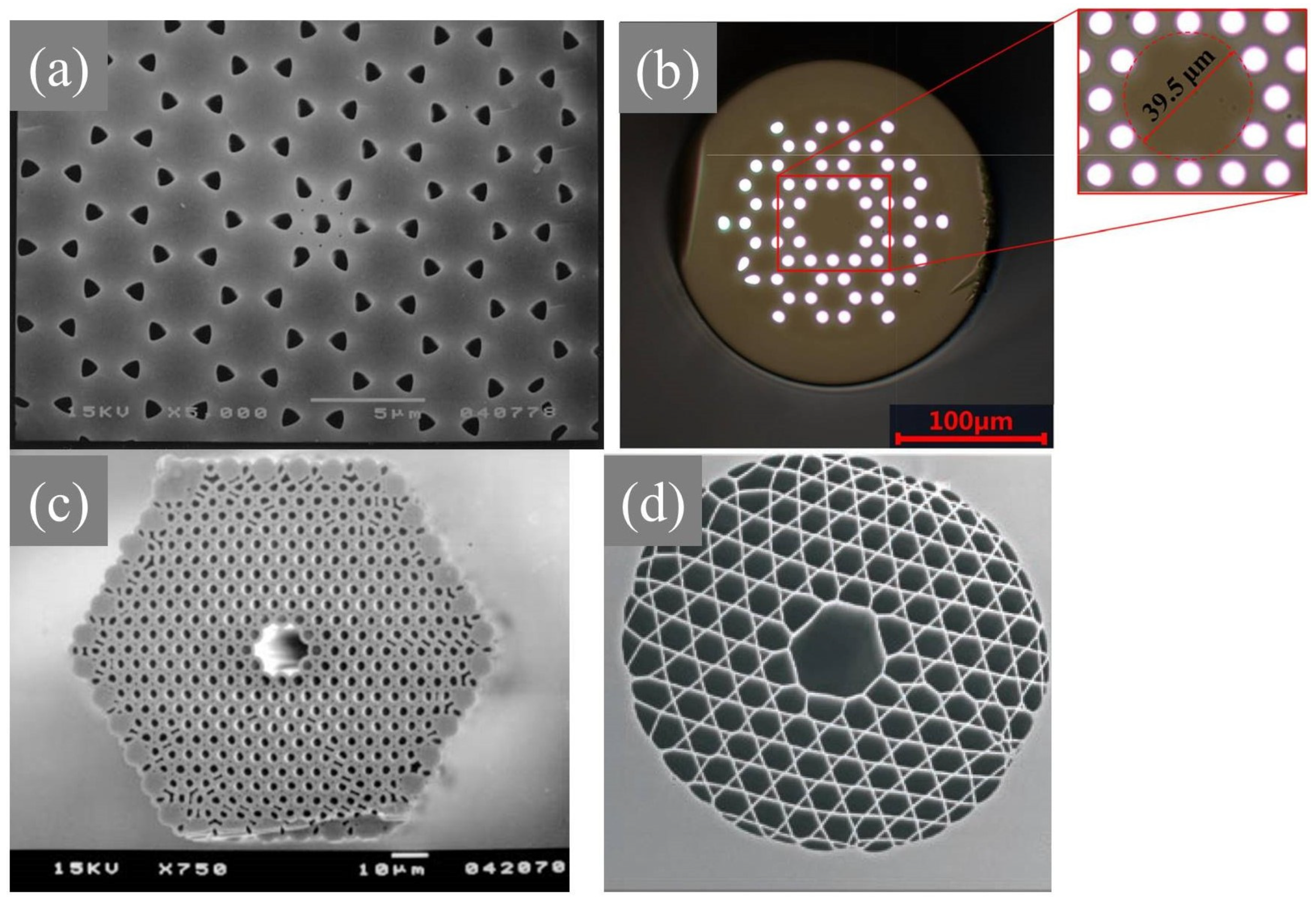
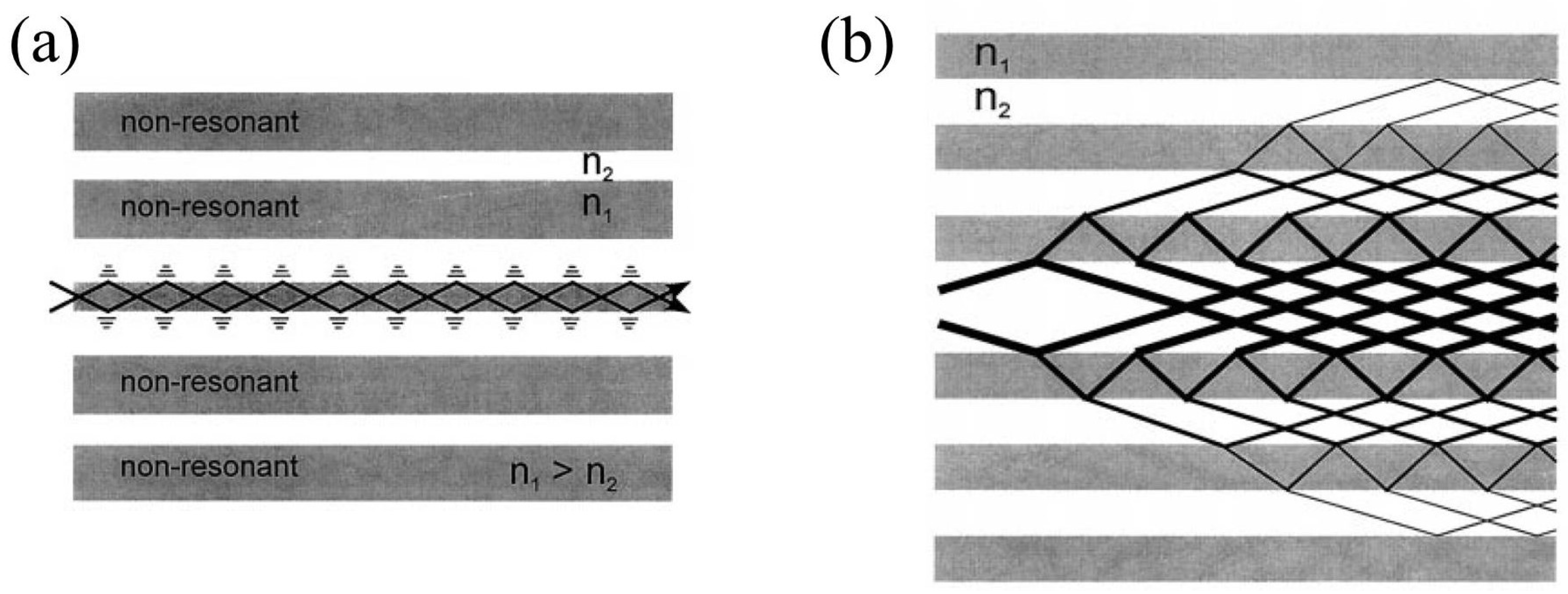
With the development of the fabrication process, photonic bandgap fibers (PBGFs) with more stringent requirements on the cladding microstructure were developed, which have a completely different guidance mechanism from that of TIR-type fibers; their core refractive index is smaller than that of the cladding, so the TIR effect is not possible. The first PBGF (honeycomb structure) based on the PBG mechanism for guiding light was developed by Knight et al. in 1998 [23] (Figure 2a), and its guiding mechanism is the frustrated tunneling PBG effect. One type of PBGF is the all-solid PBGF [24], which was developed on the concept of filling the air holes of TIR fibers with a high refractive index medium (Figure 2b). In 1999, the first hollow-core PBGF (HC-PBGF) was developed [25] (Figure 2c). Its working principle is the Bragg PBG effect. The frustrated tunneling PBG effect and the Bragg PBG effect both belong to the PBG effect, and the basic principle can be explained by the fact that with proper structural design, light whose frequency falls in the bandgap cannot propagate in the periodic structure and is constrained within the fiber core. The guidance mechanisms are shown in Figure 3.
More commonly known among these is the HC-PBGF. The fiber core is alternately surrounded by materials with high and low refractive indices, and the structure creates a photonic crystal bandgap that restricts the propagation of a specific frequency of light to the core with the lower refractive index. The frequency can be modulated by controlling the distance between the neighboring low refractive index locations. In 2003, Corning Incorporated increased the air-filling ratio of HC-PBGF to more than 90% [27], and now usually the air-filling ratio of HC-PBGF is greater than 90%. HC-PBGF overcomes the limitations of solid-core MOFs in terms of damage thresholds, dispersion, and nonlinearity, which greatly improves the power transmission level in the fiber and reduces the loss. Moreover, by filling with different gases, dispersion, nonlinearity, and other parameters can be customized, and its combination with ultrafast lasers has given rise to many amazing studies.

2.3. Hollow-Core Anti-Resonant Fiber

The hollow core anti-resonant fibers (HC-ARFs) can be traced back to kagome-type hollow core fibers, and they were derived from negative curvature hollow core fibers in 2010, which were found to have greatly reduced losses. The fabrication of ARFs can be traced back to 2011 when Andrey D. Pryamikov et al. [28] demonstrated a hollow core fiber with cladding consisting of single-ring tubes (Figure 4a). Unlike both the TIR-type fibers and the HC-PBGFs, its cladding does not require a periodically arrayed structure; instead, it consists of several tubes, and the core is filled with air. Some types of ARFs are shown in Figure 4.
In 1986, Duguay et al. [31] proposed a new theoretical and experimental model of antiresonant reflecting optical waveguide (ARROW), which was first used for air flat waveguides, and in 2002, Litchinitser et al. introduced it into the explanation of the light guiding mechanism of MOFs [32]. The theoretical model of ARFs can be explained by a theory similar to the Fabry–Perot cavity (as shown in Figure 5). Assume that when light in the fiber core passes through the capillary wall directly, the phase is φ0, and when light in the fiber core passes through the capillary wall after two reflections in the capillary wall, the phase is φ1. At this time, if the phase difference Δφ satisfies an even multiple of π, most of the light passes through the capillary wall and enters into the single ring structure, which is the resonant condition, whereas if the phase difference satisfies an odd number of times of π, then most of the light is reflected to the core, and it is constrained to the core, which is the anti-resonant condition.
In general, the resonant wavelength of an ARF can be expressed as:
λ m = 2 t m n 1 2 1 , m N +
the anti-resonant wavelength can be expressed as:
λ m = 2 t m 0.5 n 1 2 1 , m N +
where λ is the wavelength, t is the thickness of the glass capillary wall, n1 is the refractive index of the glass material, and m is the order of the resonant wavelength. It can be seen that the light transmitted in the fiber core is between two adjacent resonant wavelengths. ARFs have multiple transmission ranges, and the resonant wavelength is inversely proportional to the order m, so the higher order corresponds to a narrower bandwidth. ARFs have been widely studied due to their simple structure, wide transmission bandwidth, and large core size. However, they are susceptible to bending due to their light-guiding mechanism.

2.4. Hybrid Light Guiding MOFs

Hybrid light-guiding MOFs are a combination of the above optical fibers, for example, combining a TIR fiber with a PBGF [33], which is PBG light guiding in the horizontal direction and a TIR mechanism in the vertical direction (as shown in Figure 6). Along the vertical direction, the core has a higher refractive index than the effective refractive index of the cladding, so along this direction, light can be guided by the TIR mechanism. On the other hand, along the horizontal direction, TIR is not possible since the cladding rods have a higher index than the core, and light is constrained by the PBG mechanism. Such fiber better represents the flexibility of MOFs in their structural modulation.

3. Applications of MOFs in Ultrafast Optics

In the previous section, we introduced several common types of MOFs. In this section, we will introduce the applications of MOFs in ultrafast optical fields, including pulse amplification, supercontinuum generation, pulse compression, etc. The combination of MOFs and ultrafast optics opens new horizons to the world of optics, and the flexible modulation of MOFs realizes many impossible visions.

3.1. Pulse Amplification

One of the critical problems of laser amplification is heat dissipation. Fibers have a large ratio of surface-to-active volume, which makes them good mediums for laser amplification. There are many types of fiber laser amplifications: direct amplification of doped fibers, fiber Raman amplification, fiber optical parametric amplification, etc. Ultrafast laser amplifiers based on ytterbium-doped fiber can generate very high average power with pulse durations as short as tens of femtoseconds, since ytterbium-doped fibers provide optical-to-optical efficiencies well above 80%, hence becoming the first choice among the rare-earth ion-doped fibers [34]. Here we take ytterbium-doped MOFs as a clue and briefly introduce their application in laser amplification.
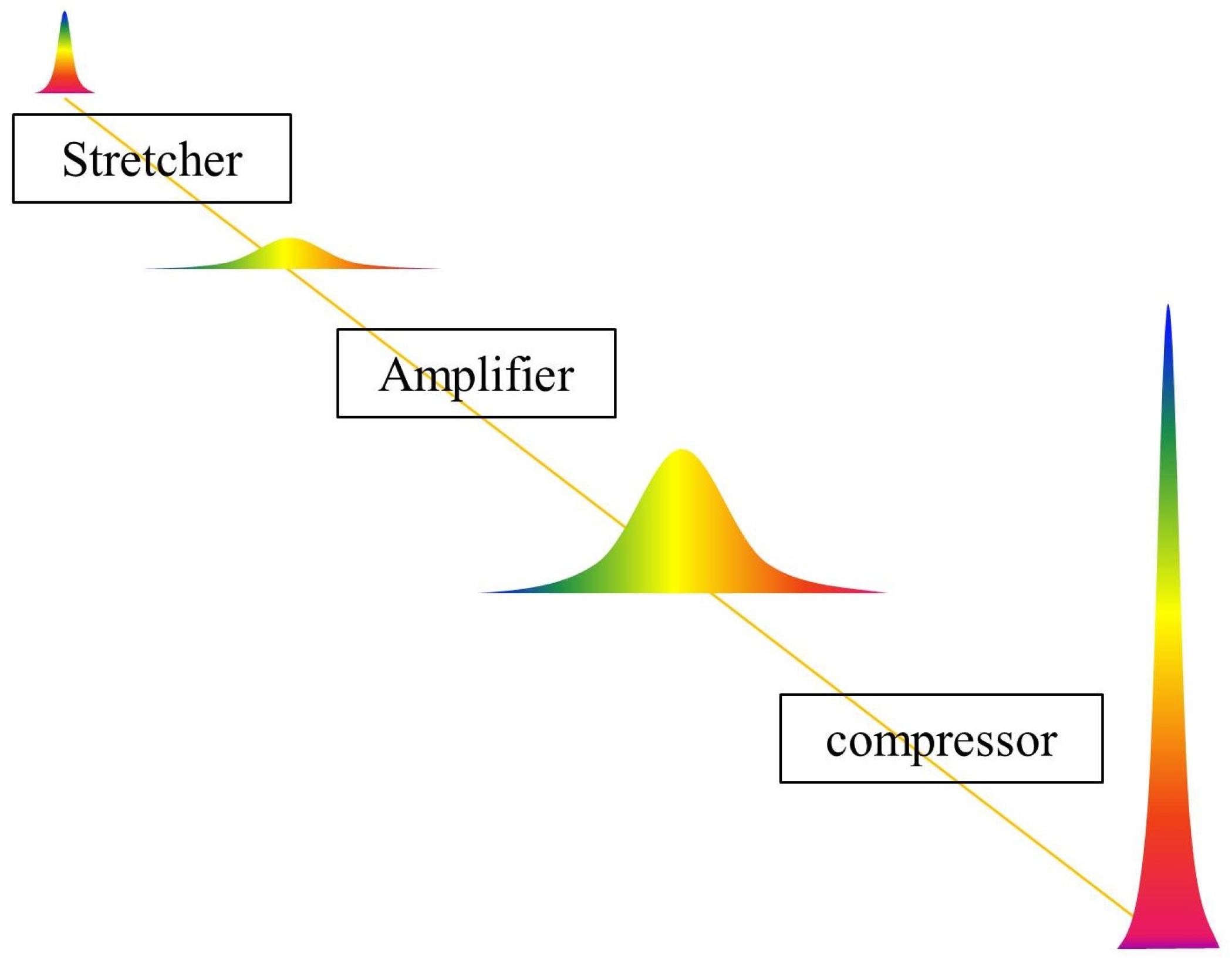
In fibers, the confinement of the light in a small core results in large intensities interacting with the material over long lengths, which triggers detrimental nonlinear effects. The amplification of ultrashort pulses directly in single-mode fibers is susceptible to the huge influence of nonlinear effects (self-phase modulation, stimulated Raman scattering (SRS), etc.), which leads to pulse distortion. In 2003, Limpert et al. constructed a chirped pulse amplification (CPA) system (schematic diagram illustrated in Figure 7) using Yb-doped double-clad fiber to reduce the peak power density in the core by several orders of magnitude to reduce the nonlinear effects. The final output with 76 W average power and 400 fs pulse width at 75 MHz repetition rate is obtained [35]. The oscillator is a 144 fs Nd:glass laser with a center wavelength of 1060 nm. The large mode area (LMA) of the ytterbium-doped fiber for the second-stage amplification is 415 μm2, which is the key to realizing the transmission of femtosecond pulses with tolerable peak power density.
Two years later, Limpert et al. designed Yb-doped rod-type PCFs, which are capable of providing high power extraction at short fiber lengths, solving the thermo-optic problem of coating damage. Due to the microstructure design of the PCF, it can output beam quality close to the diffraction limit. An output of 120 W with a center wavelength of 1035 nm was achieved, and the extracted power was 250 W/m; this was the highest value ever reported for fiber lasers at that time [36]. Subsequently, Röser et al. utilized Yb-doped rod-type PCF to build a CPA system with 100 W average power, 1 mJ pulse energy (the highest pulse energies ever reported from a fiber-based ultrafast laser system at that time), and an 800 fs pulse width. The first stage was a 1.2 m long air-clad PCF amplifier, and the second stage employed a 1.2 m long low-nonlinearity air-cladding rod-type PCF [37]. With the development of semiconductor lasers and PCF fabrication processes, higher output power was realized in an all-fiber system. Eidam et al. achieved 830 W average power by using a Yb-doped fiber CPA system, generating 640 fs pulse duration at a 78 MHz repetition rate [38]. The first stage of amplification consisted of a 1.2 m and 1.5 m Yb-doped double-clad PCF with a 30 μm core mode field and a 170 μm cladding mode field. The power output from the first stage could reach 100 W but was limited to 50 W to avoid the thermal lens effect in optical Faraday isolators. The main amplifier’s fiber was a water-cooled 8 m-long double-clad fiber with a 27 μm mode field diameter and 500 μm air clad.
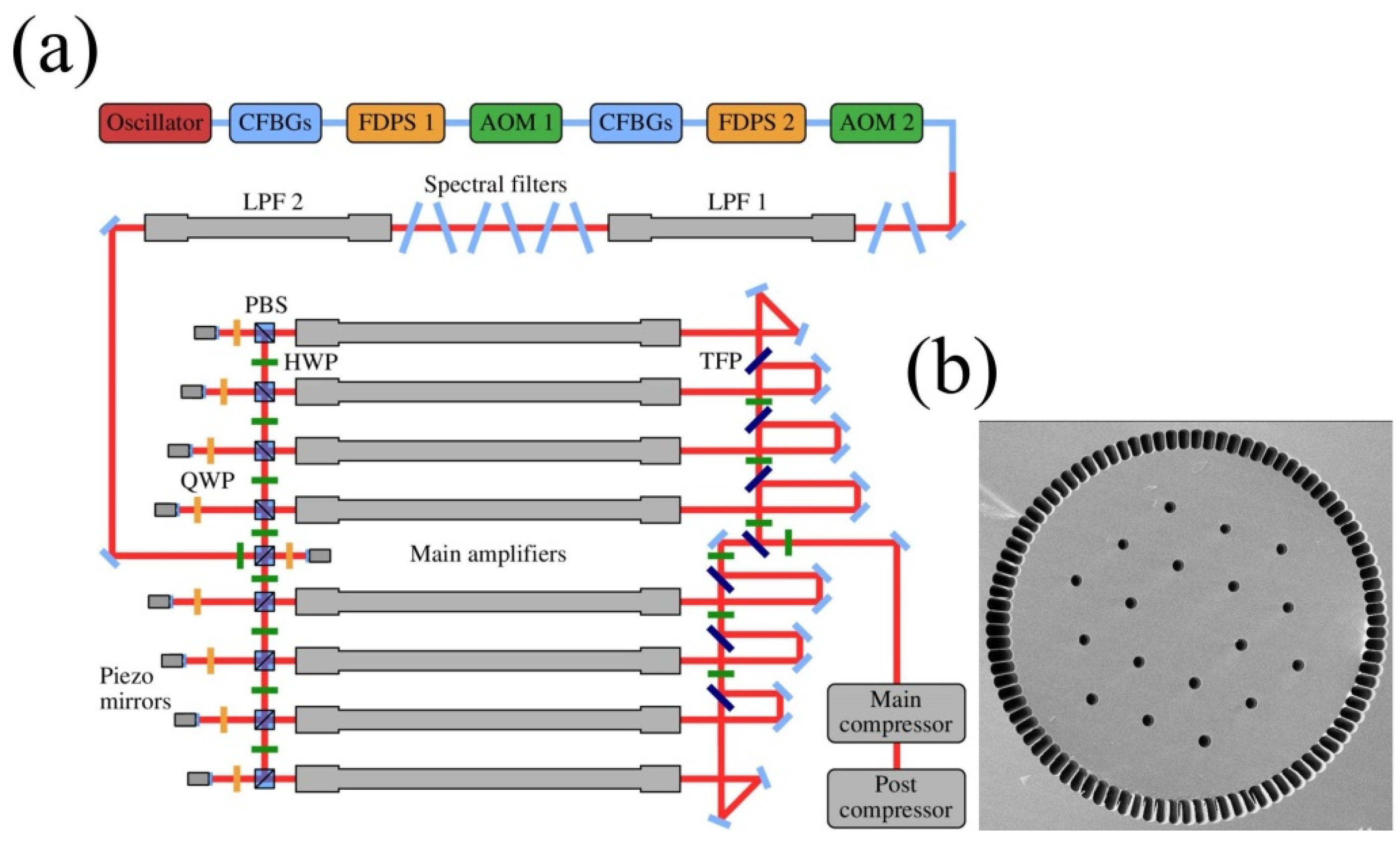
Wan et al. constructed two kinds of all-fiber systems: Yb-doped high-energy and high-power femtosecond fiber lasers, respectively [39]. High energy system output: 1 mJ pulses at 100 kHz and 705 fs pulse duration; high power system output: 1052 W average power at 69 MHz and 800 fs pulse duration. The high energy system employed a Yb-doped ultra-large-core single-mode rod PCF seeded with a 50 µJ chirped pulse fiber laser. The high power system’s active medium was an 8 m-long double-cladding LMA fiber with a core diameter of 30 µm. However, continuing to increase the power of fiber lasers is limited by mode instability and excessive nonlinearity. In order to avoid these limitations, Müller et al. built an ultrafast fiber CPA system comprising eight coherently combined amplifier channels, boosting the average power to 1000 W with 1 mJ pulse energy and 260 fs pulse duration by employing large-pitch fibers (LPFs) with mode-field diameters as large as 64 μm [40]. Further, Stark et al. built a coherently combined Yb-doped LPF CPA laser system that outputs 1000 W average power with 10 mJ pulse energy and 120 fs pulses [41] (as shown in Figure 8). In 2023, Stark et al. boosted the data to 32 mJ and 158 fs at a 20 kHz repetition rate with an average power of 640 W, which was achieved by 16 parallel Yb-doped rod-type amplifiers [42]. It is worth pointing out that the output power of fiber lasers can reach more than 10,000 W through similar coherent combined amplification [43].

3.2. Spectrum Engineering

MOFs have been used in numerous works for spectral engineering, and their versatile structure allows different nonlinearities and dispersions to be met, which has enabled the realization of many ideas in spectrum modulation. In this subsection, we introduce the applications of MOFs in supercontinuum generation (SCG), UV generation, and IR generation.

3.2.1. Supercontinuum Generation

The pursuit of the generation of different wavelengths of light has been ceaseless; different wavelengths of light have their own applications, and the emergence of supercontinuum has opened up a new perspective. SCG is undoubtedly one of the most successful applications of PCF. The generation of supercontinuum (SC) is achieved by the use of narrowband pulses incident on a nonlinear medium, resulting in a significant broadening of the spectrum. Compact SC sources are indispensable in many optical laboratories. The SCG was observed for the first time in 1970 when Alfano et al. launched picosecond pulses into a bulk optical crystal [45]. The emergence of the PCF provides an excellent nonlinear guiding medium for SCG with manageable nonlinearity and zero-dispersion wavelengths (ZDW) [46], enabling very strong spectrum broadening with a low-power pumping source such as a high-repetition-rate femtosecond laser resonator. In 1999, Ranka et al. demonstrated experimentally for the first time a broadband spectrum spanning from UV to NIR generated in a PCF with ZDW around 780 nm when pumped by 100 fs, 790 nm pulses with a peak power of kilowatts [47]. Subsequently, there has been a lot of research on PCFs to generate SC light, and the mechanisms and mathematical models have been intensively investigated [48,49]. Birks et al. pumped a tapered fiber with 200 fs, 3.9 nJ pulses from a Ti:sapphire laser, producing a broad spectrum from 400 nm to nearly 1600 nm [50]. Genty et al. used a 5 m long PCF with a highly birefringent elliptical core, produced a SC spectrum from 400 nm to beyond 1400 nm, and found that the experiments agreed well with their theories. The pump source was a Ti:sapphire laser with 100 fs pulse duration, 80 MHz repetition, and 1.7 W average power [51]. At the beginning of the 21st century, a lot of work was conducted by pumping PCFs with different experimental conditions (e.g., different pulse conditions or different structures of PCFs) to study the nonlinear and dispersion mechanisms in SCG [52,53,54]. It is worth pointing out that these PCFs are mostly solid and based on the refractive index guidance.
Extension of the spectrum to the UV direction was carried out by various methods, including the use of cascaded PCFs, tapered PCFs, nanoscale fibers, etc. (summarized in Table 1). Stone and Knight from Bath University obtained a spectrum from 350 nm up to 2450 nm, 50 nm deeper into the short-wave direction than the previous works, by modifying the structure of the PCF (see Figure 9) when pumped by a microchip laser with a pulse width of 600 ps at 1064 nm [55]. Chen et al. pumped 700 ps pulses at 1064 nm into a system consisting of three tapered PCFs in cascade to produce a SC spectrum spanning from 352 nm to 1750 nm [56]. Stark et al. used 800 nm, 130 fs, and 2 nJ pulses to pump a tapered solid core PCF to produce a SC spectrum down to 280 nm and found that the deep-UV radiation is limited by strong two-photon absorption in silica [57].
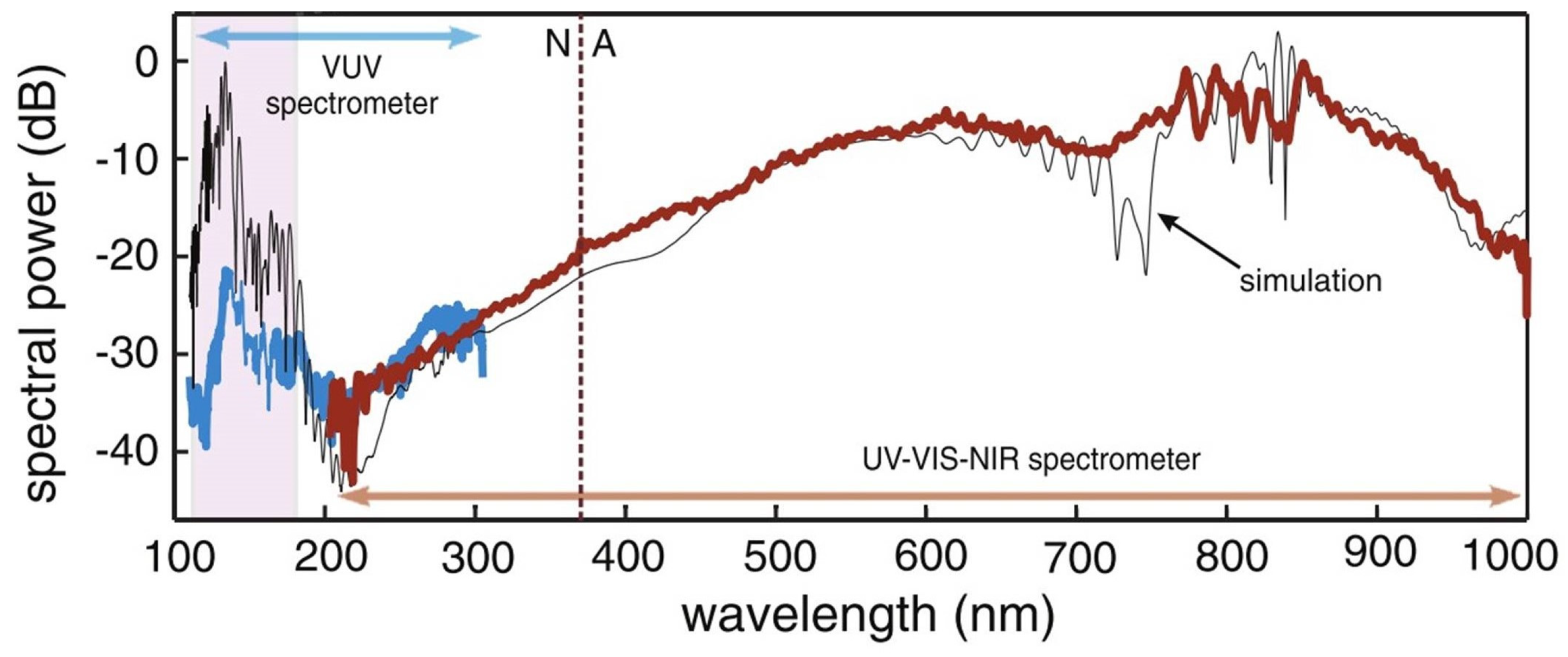
In terms of a high-power SC source, Qi et al. pumped 120 ps pulses at 1016 nm into a multi-core PCF, which was designed to provide strong dispersion to satisfy the conditions for UV SCG. The system outputs an 80 W SC light from 350 to 2400 nm [58]. Zhang et al. made an all-fiber SCG system using 1064 nm picosecond pulses pumped cascade PCF to obtain 104 W SC output covering 370 nm to 2400 nm [59]. It is difficult for a solid-core PCF to produce light at deeper UV. Ermolov et al. overcame this limitation by introducing a He-filled HC-kagome-style PCF. They launched linearly polarized, 35 fs, 1 kHz pulses at 800 nm generated by a Ti:sapphire amplifier into the He-filled HC-PCF and produced a SC covering 113 nm vacuum ultraviolet to 1000 nm NIR [60], where the key point is that the ZDW of the HC-PCF is in the UV region. In Section 3.2.2, more research on UV generation will be discussed.
Figure 9. Experimental spectra of SCG. The blue curve was measured by the VUV spectrometer, and the brown curve was UV-NIR spectrometer. The solid black line is the simulated spectrum. The dashed vertical line marks the ZDW (N = normal, A = anomalous GVD) [60].
Photonics 11 00151 g009
Silica fibers limit the extension of SCG in the IR region to the vicinity of 2 μm due to the transmittance range. Researchers have gradually adopted other highly nonlinear materials for manufacturing PCF as the medium for SCG, such as tellurite, fluoride, chalcogenide (ChG), etc., which have a longer transparent edge in IR and can be well used as the medium for IR SCG (summarized in Table 2). Delmonte et al. used a femtosecond OPO output of 1.5 μm to pump a tellurite wagon wheel MOF to produce a SC from 0.9 to 2.5 μm [61]. Domachuk et al. launched 1550 nm, 100 fs pulses into a section of a highly nonlinear tellurite microstructured PCF to produce SC extending from 789 nm to 4870 nm, which occurs in a sub-cm (8 mm) length of this PCF [62].
Among several types of promoting mid-IR optical glasses, optical fibers made of selenides and sulfides are extremely fragile, and toxic compounds are added to improve nonlinearity, whereas these problems can be avoided by using heavy metal oxide glasses. Buczynski et al. pumped 1540 nm, 150 fs pulses into a single-mode PCF made of lead-bismuth-gallate glass, producing a SC spectrum from 700 nm to 3000 nm [63], which was the broadest SC reported in heavy metal oxide glass fibers at that time.
ChG has an extremely wide transparency window (over 20 μm) and high nonlinearity (up to a thousand times greater than that of silica glasses), which make it one of the outstanding candidates for mid-IR SCG. Liu et al. obtained 2.2~3.3 μm SC from an all-solid ChG MOF with all-normal dispersion. The pump is an OPO output pulse with 2.7 μm, 200 fs, and 80 MHz [64]. Wang et al. pumped ChG step-index tapered fibers with 3.25 μm, 150 fs pulses in the normal dispersion regime and obtained a SC from 1.4 μm to 7.2 μm [65]. Xing et al. obtained a SC from 1670 nm to 2880 nm by pumping ChG PCF with pulses of 79 fs, 2070 nm, and 2.9 kW peak power. Their simulation by utilizing the generalized nonlinear Schrodinger equation model was in agreement with the experimental results [66].
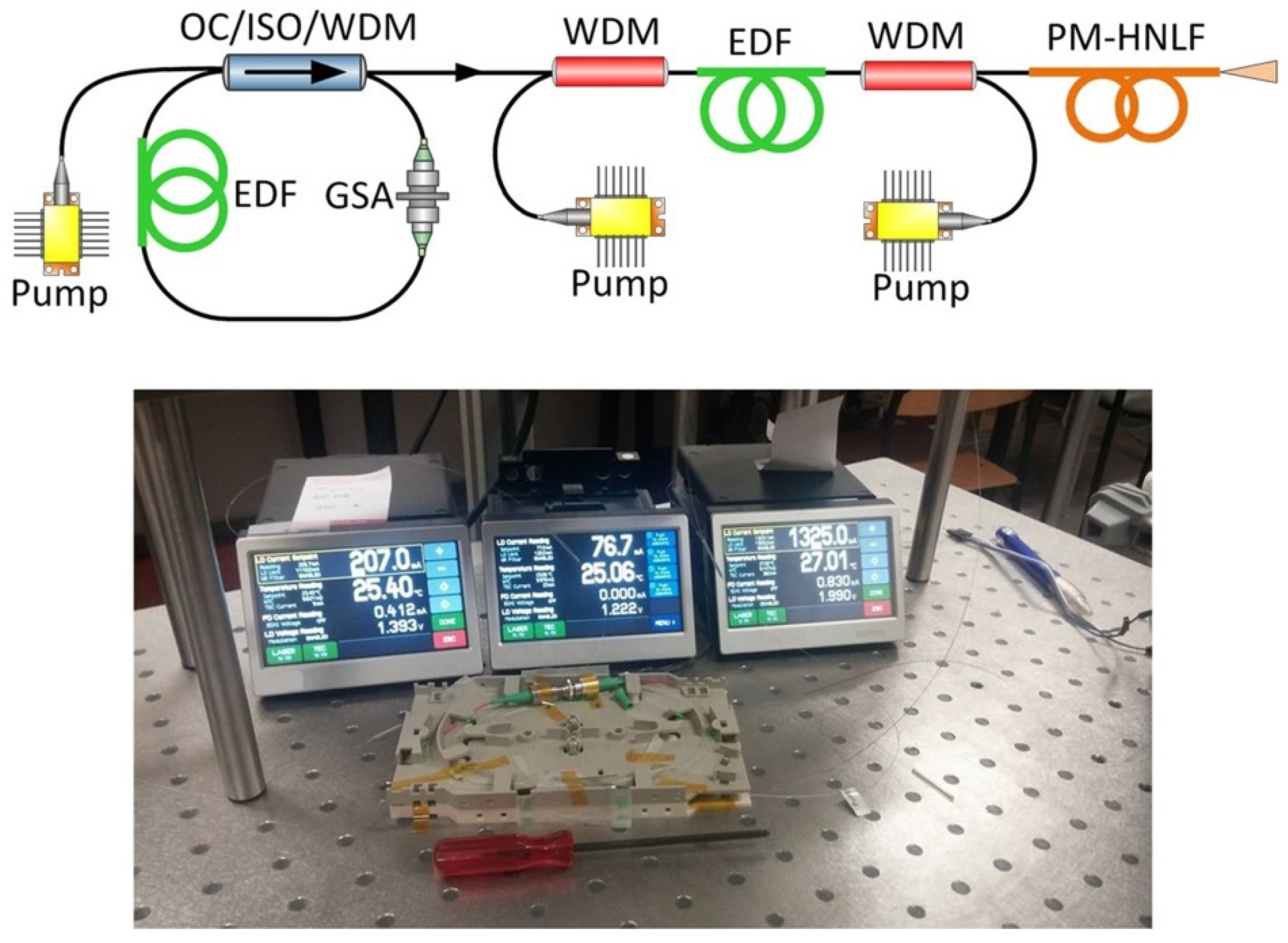
Moreover, Tarnowski et al. reported a very compact all-fiber SC source (see Figure 10). By pumping the 25 fs, 116 mW pulses from Er-doped fiber into an all-normal dispersion MOF, a SC from 1.1 to 2.2 μm was obtained [67], which is simple and opens the path to outside-lab applications of SCG. In 2021, Zhu et al. used a dual-band MOPA system (1 μm and 1.5 μm) to pump a cascaded PCF to generate a 500~3000 nm SC with a maximum output power of 9 W [68]. Which is the highest power ever achieved from a SC source spanning from the visible to mid-infrared at that time.

3.2.2. UV Generation

Ultrafast UV lasers have significant value in many applications due to their unique properties. Short-wavelength light has a smaller focusing area and higher photon energy, which are important in fields such as attosecond science [9], photolithography [69], etc. Ultrafast UV generation can be sorted by mechanisms, such as high harmonic generation (HHG) [70,71], third harmonic generation of NIR [72,73], filtering out the UV portion of the SCG, dispersive wave emission [74], and so on. We take the gas-filled HC-PCF as a clue to illustrate its application for UV generation in terms of HHG and dispersive wave emission. Using gas-filled HC-PCF to generate ultrafast UV lasers can eliminate the diffraction of light in gases so that the UV output has excellent beam quality. Moreover, HC-PCF has high UV transparency and is less susceptible to material damage than solid materials.
HHG can produce very short wavelength output in extreme UV or even soft X-ray regions, and the mechanism can be explained by the three-step model [75]. Conventionally, intense infrared laser pulses are tightly focused into a noble gas jet to obtain HHG, which restricts the interaction length to the Rayleigh range of the focus. Utilizing a gas-filled HC-PCF to generate HHG can increase the interaction distance and obtain excellent conversion efficiency at low-energy pulses. In 2009, Heckl et al. first obtained HHG up to the 13th harmonic in a 15 mm-long kagome-type HC-PCF filled with Xe (see Figure 11). The system was pumped by an 800 nm, 10 μJ, 30 fs, 1 kHz Ti:sapphire laser, implying a UV wavelength that reaches near 50 nm [76], but the conversion efficiency was very low (10−9). Imperfect phase-matching leads to a significant reduction in the efficiency of HHG. Wiegandt et al. developed a time-multiplexed multimodal quasi-phase-matching technique that can solve the problem of efficiency. They used a negative-curvature PCF filled with Ne to obtain HHG up to 39th when pumped by pulses of 30 fs and 15 μJ at 790 nm, implying a high harmonic wavelength down to 20 nm, photon energy up to 61.6 eV, and a 60-fold enhancement of the HHG flux [77]. Tani et al. combined a gas-filled HC-PCF with a gas jet for HHG driven by laser pulses of a few tens of microjoules and obtained an output tunable from 17 to 45 eV [78].
The UV generation from filtered SCG in a solid-core PCF has low brightness and is limited to 280 nm [57]. In contrast, the UV generated by the dispersive wave mechanism of a gas-filled HC-PCF can concentrate the energy into a narrower bandwidth, which is an excellent method to obtain a tunable UV output. The dispersive wave emission originates from the fundamental soliton propagation perturbed by high-order dispersion [79]. Joly et al. utilized 800 nm, 30 fs, and 1 μJ pulses to pump an Ar-filled HC-PCF and generate 200~320 nm tunable UV light. The wavelength tuning was achieved by varying the pulse energy, gas pressure, and IR to UV conversion efficiencies of up to 8%, with a threshold as low as 290 nJ [80]. Mak et al. conducted further study by pumping a HC-PCF filled with different gases using a light source of 800 nm and obtained a tunable output from 176 nm to 550 nm (see Figure 12). They also carried out numerical simulations, which were in good agreement with the experimental results [81].
Lowering the pumping energy threshold for obtaining UV output is desired. Recently, Sabbah et al. utilized an Ar-filled ARF with a core diameter of just 6 µm, which is much smaller than previous studies, and obtained a 220~700 nm spectrum with an input pulse energy of as low as 50 nJ [82]. While dispersive waves are usually used as a means of generating UV light, Meng et al. obtained additional NIR output, along with the 267~460 nm spectrum, by pumping a 42 cm-long Ar-filled kagome PCF with pulses of 40 fs at 1 μm and interpreting it with a more accurate antiresonant tube model [83].

3.2.3. IR Generation

Raman soliton self-frequency shift (SSFS) is one of the most effective methods to extend the wavelength to a longer region. It is the redshift of the wavelength of a high-peak power pulse under the effect of stimulated Raman scattering when it is transmitted in a nonlinear medium with anomalous dispersion. SSFS generates continuously tunable femtosecond pulses with a relatively concentrated spectrum, avoiding the utilization of extra nonlinear frequency conversion efforts such as optical parametric oscillators. There has been a lot of research on the SSFS since the emergence of PCF. Washburn et al. used a 110 fs, 806 nm Ti:sapphire laser-pumped 1.7 m PCF to produce Raman solitons tunable from 850 nm to 1050 nm [84]. Liu et al. launched 200 fs, 1.3 μm, 80 MHz pulses into a tapered air-silica MOF and obtained soliton pulses tunable in the range of 1.3 μm to 1.65 μm with a compressed pulse duration of less than 100 fs [85]. Nishizawa et al. used a 780 nm frequency-doubled Er-doped fiber laser to pump a 60 cm PCF and produced femtosecond tunable soliton pulses in the range of 780 nm to 900 nm [86]. A shorter pulse width benefits the SFSS effect greatly. Ishii et al. shifted a 6 fs Ti:sapphire laser pulse from 800 nm to 1.35 μm continuously by the SSFS effect in the PCF [87]. Using a highly nonlinear PCF, Chan et al. produced a 1245~2160 nm tunable output, and the range has reached the upper boundary of silica material, with pump pulses of 65 fs at 1245 nm [88].
OH absorption is a limiting factor in the SSFS when pumping below 1380 nm. Dekker et al. designed a PCF with reduced OH loss and produced a tunable output over more than an octave from 801 nm to 1708 nm [89]. Yuan et al. purified the silica material of PCF by the complex method of rectification and adsorption, greatly reduced the contents of OH, metal ions, and metallic and non-metallic oxides, and then obtained soliton pulses above 2 μm with a tuning range of 300 nm when coupled at 870 nm into a highly birefringent PCF [90]. While many fibers for SSFS are designed for only one wavelength, Szewczyk et al. designed a highly birefringent MOF that can be applied to SSFS at both 1.04 μm and 1.55 μm. With 1.04 μm pumping, the soliton pulses can be continuously tuned from 1.04 μm to 1.67 μm, and with 1.55 μm pumping, the pulse can be continuously tuned from 1.55 μm to 1.95 μm [91]. This has promising applications in multiphoton imaging and other areas.
The absorption loss of silica limits the SSFSs ability to achieve wavelengths longer than 2 μm. However, light sources above 2 μm are in the eye-safe range and have important applications, such as medical treatment. Bi et al., using a tellurite MOF, obtained the wavelength shift range from 1990 nm to 2264 nm by merely varying the pump power of a Tm-doped mode-locked fiber laser with a pulse width of 2.9 ps and a center wavelength near 2 μm [92]. Alamgir et al. employed an 8 cm highly nonlinear As2S3 tapered suspended core MOF for achieving tunable outputs from 2.04 μm to 2.66 μm [93].

3.3. Pulse Compression

Generally, fiber lasers are not the best candidates for the generation of femtosecond pulses with a duration less than 100 fs due to their high order dispersions and relatively narrow gain bandwidth, which hampers their merits of excellent long-term stability and tractability of thermal problems and limits their applications where high power and short pulse duration are both important [94]. Conventionally, chirped mirrors, grating pairs, or prism pairs are used to compress ultrafast pulses, but they are designed and manufactured for a specific wavelength range, whereas HC-PCF offers a much less complex and lower-cost route to pulse compression, and it can be used in any spectral region. The soliton dynamics in a gas-filled HC-PCF combine both nonlinearity and dispersion, leading directly to extreme self-compression.
The use of nonlinear effects in optical fibers for pulse duration compression has been studied for a long time. In 1983, Mollenauer et al. compressed 1.5 μm, 7 ps pulses to 260 fs using a single-mode fiber [95]. The emergence of PCF makes ultrashort laser pulse compression effective by bringing about flexible dispersion and nonlinearity engineering. Limpert et al. first demonstrated the compression of 1040 nm pulses that had been broadened to 1.9 ps to 100 fs using a HC-PBGF [96]. With the development of PCFs, anomalous dispersion at shorter wavelengths has been achieved. Travers et al. used a tapered PCF to compress 1.06 μm, 830 fs pulses to 55 fs [97].
Utilizing solid-core PCF for compression, the maximum peak power is limited to a few megawatts by material damage and the self-focusing threshold. While HC-PBGFs effectively alleviate this problem, their narrow transmission bandwidth and strongly varying dispersion limit their applications in few-cycle pulse compression. The kagome-PCFs have substantially broader guidance windows, with weakly anomalous dispersion. Mak et al. utilized two-stage kagome-PCF to compress 250 fs, 1 μJ pulses from a mode-locked Yb:YAG thin-disk oscillator to 9.1 fs, in which the first stage was a 70 cm Kr-filled kagome-PCF with a 36 μm core diameter, and the second stage was a 25 cm kagome-PCF of the same configuration filled with Ar [98]. Ermolov et al. used a 10 cm kagome-PCF with a 33 μm hollow core diameter to compress 9 fs, 3.5 μJ, 800 kHz pulses at 800 nm output from the optical parametric chirped-pulse amplification (OPCPA) system to 4.4 fs, and the pulse carrier-envelope phase (CEP) was stabilized [99]. With kagome-PCFs, it is possible to compress UV pulses as well as IR pulses. For UV pulse compression, Luan et al. generate 7.6 fs near-UV pulses centered at 400 nm in an Ar-filled HC kagome-PCF [100]. For IR pulse compression, Murari et al. utilized a two-stage kagome-PCF to compress 140 μJ, 3.3 ps pulses at 2 μm to 48 fs, leaving 11 μJ pulse energy after compression. The first stage was a 3 m HC-kagome PCF filled with Ar-gas to broaden the spectrum, and the second stage was a 2 m HC-kagome PCF filled with air for pulse compression [101].
The ARF developed from the Kagome PCF is also characterized by broadband low loss and a high damage threshold and is also suitable for high-power laser compression. Elu et al. used a 16.9 cm Ar-filled ARF with 12 bar pressure to compress the pulses from a CEP stable mid-IR OPCPA. The pulses of 3.3 μm, 97 fs, and 131 μJ were compressed to 14.5 fs, and the system output power was 9.6 W [102]. Köttig et al. utilized a two-stage compression system to compress 320 fs pulses from a Yb-doped fiber laser and obtained 3.8 fs, 5 µJ output pulses at a 9.6 MHz repetition rate, with total transmission exceeding 66% (see Figure 13). The first stage was used for spectral broadening with a Kr-filled ARF, and phase compensation was achieved with chirped mirrors. In the second stage, pulses were compressed to single-cycle duration by soliton self-compression in a Ne-filled ARF [103]. Moreover, Travers et al. investigated the soliton dynamics of self-compression and UV generation in HC-PCF through a series of experiments, providing guidance on the new generation of table-top light sources for ultrafast strong-field physics [104].
Furthermore, in the aspect of using MOFs for high power or high pulse energy compression, some works from ELI employed MOFs to compress ultrafast lasers of 45 mJ [105] or 580 W [106] to tens of femtoseconds.

3.4. High-Harmonic Mode-Locking Soliton Lasers

Optical soliton is a special form of ultrashort pulse, i.e., a pulse whose shape, amplitude, and speed remain constant during propagation. Optical solitons can be used as soliton communications, which completely eliminates the limitation of fiber dispersion on transmission speed and communication capacity. Under certain conditions, it can realize ultra-long-distance and ultra-large-capacity communication and is regarded as the most promising next-generation communication transmission method.
As early as 1987, Mitschke and Mollenauer realized a 50 fs soliton laser [107]. Whereas for communication, it is required that the laser have a high repetition frequency, to generate pulses with a high repetition frequency, high harmonic mode-locking (HHML) schemes have been proposed, including active mode-locking [108] or passive mode-locking [109]. The HHML is a result of long-range repulsive interactions of solitons, where pulse splits in the buildup process of mode locking and the solitons repel each other as a result of time-dependent gain depletion and recovery, which impose phase shifts and consequently relative group velocity changes on the solitons [110]. However, many approaches to HHML require complex and precision modulation devices, while mode-locking at high harmonics can be easily achieved based on the mechanism of optoacoustic interaction in the PCF. Pang et al. utilized a short-length (60 cm) PCF with a small solid glass core, passively mode-locked at a high harmonic (~2 GHz) of its fundamental frequency [111]. The key is that the long-lived acoustic vibration provides strong modulation of the refractive index in the PCF core. In the same team, He et al. inserted a Fabry–Perot-based tunable filter into an optoacoustic interaction HHML fiber laser system and realized wavelength tunability from 1532 nm to 1566 nm without affecting the HHML of the laser system at 1.88 GHz [112] (see Figure 14). He et al. also realized a stretched soliton all-fiber laser that reduced the energy for producing solitons to only tens of pJ and produced sub-100-fs pulses at 1.87 GHz [113]. Yeh et al. used a 2 m tapered PCF to make the pulse repetition rate tunable over 66 MHz (from 2.042 to 2.108 GHz) of an optoacoustically mode-locked soliton fiber laser at 1.55 μm [114].
Moreover, HHML can also be performed using nonlinear multimode interference. Li et al. achieved a stable mode-lock at 1.26 GHz using tapered graded-index multimode fiber, corresponding to the 22nd harmonic of the fundamental frequency [115].

3.5. Coherent Anti-Stokes Raman Scattering

As one of the important development directions of traditional optical microscopic imaging technology, nonlinear optical microscopic imaging takes the light generated by nonlinear processes in the sample as the signal, which can realize the specific observation of the sample and break through the diffraction limit of resolution. In the two decades of rapid development, the coherent anti-Stokes Raman scattering (CARS) technique, as a kind of nonlinear optical micro-imaging, has received wide attention because it can realize label-free and non-invasive imaging of the sample [116]. Since the CARS system requires tuning the frequency difference between the pump pulse and the Stokes pulse, many CARS systems are based on OPO constructs. Conventional OPO systems are complex and require regular maintenance by specialists. The combination of CARS and PCF makes the CARS system expected to go out of the laboratory.
The CARS signal was first observed experimentally in 1965 by Maker et al. [117]. Subsequently, the theory of CARS has been intensively investigated. In 1982, Duncan et al. used the CARS signal for micro-imaging, built the first CARS microscope based on a picosecond dye laser, and obtained CARS images of onion epidermal cells [118]. However, the drawbacks, such as its non-collinear structure, resulted in a not-very-high resolution. In 1999, Zumbusch et al. improved Duncan’s design to a collinear, tight focus structure and replaced the light source, obtaining a lateral resolution close to the diffraction limit [119]. After that, researchers mostly focused on getting higher spatial resolution, faster imaging speed, a more compact structure, etc.
PCFs play important roles in providing light sources and transmitting signals in CARS systems. Groß et al. used the SSFS in the MOF to generate solitons in the range of 800~1150 nm as the Stokes light source for the CARS system and successfully obtained CARS images of polystyrene beads and lipid distribution in an emulsion [120]. Lee et al. utilized PM-PCF to transmit the pump light and the Stokes light, which simplified the CARS system and improved its stability [121].
Most of the spectral detection techniques can only detect a species at the same time, whereas Tyumenev et al. achieved simultaneous multi-species CARS with a detection limit of 20 ppm using tapered PCF combined with single-ring ARF, where the long collinear path length offered by the ARF strongly enhanced the efficiency of the Raman interactions [122]. Alternatively, simultaneous detection of multiple Raman resonances can be realized by a multiplex CARS system. Zhang et al. used a PM-PCF to generate dual-Stokes pulses based on SSFS and birefringence effects and realized a source with two independent-tunable Stokes wavelengths [123].

4. Conclusions and Outlook

We have reviewed the applications of MOFs in ultrafast optics, including laser amplification, spectral engineering, pulse compression, high-harmonic mode-locking, etc. Many of them are based on flexible dispersion and nonlinearity engineering by modifying the structures and materials of MOFs. It is precisely this property of MOFs that can make them involved in so many applications of ultrafast optics. Among MOFs, gas-filled HC-PCF can be used for UV generation, HHG, pulse compression, and so on. It can not only realize the control of dispersive wave emission and obtain a continuously tunable ultraviolet light source but also generate high harmonics down to extreme ultraviolet and even soft X-rays and compress the pulse to a few optical cycles. For long wavelengths, soft glasses extend the spectrum generated from PCFs to the mid-IR region beyond 2.5 μm.
It is reasonable to expect that tabletop tunable deep-UV to mid-IR ultrafast lasers with sub-femtosecond pulse duration and complex mode profiles are commonly commercially available, promoting fields such as precision microscopy, atto-sciences, communications, biomedical sciences, etc.

Author Contributions

Conceptualization, J.S. and B.L.; investigation, Z.T. and Z.Z.; writing—original draft preparation, Z.T.; writing—review and editing, Z.T. and J.S.; supervision, J.S.; funding acquisition, Z.W. and J.S. All authors have read and agreed to the published version of the manuscript.

Funding

This research was funded by the National Key Research and Development Program of China, grant number 2022YFB4601103, and the Basic and Applied Basic Research Foundation of Guangdong Province, China, grant number 2022A1515140054.

Institutional Review Board Statement

Not applicable.

Informed Consent Statement

Not applicable.

Data Availability Statement

The data for this study are available from the corresponding author upon request.

Conflicts of Interest

The authors declare no conflicts of interest.

References

  1. Siek, F.; Neb, S.; Bartz, P.; Hensen, M.; Strüber, C.; Fiechter, S.; Torrent-Sucarrat, M.; Silkin, V.M.; Krasovskii, E.E.; Kabachnik, N.M. Angular momentum–induced delays in solid-state photoemission enhanced by intra-atomic interactions. Science 2017, 357, 1274–1277. [Google Scholar] [CrossRef]
  2. Géneaux, R.; Kaplan, C.J.; Yue, L.; Ross, A.D.; Bækhøj, J.E.; Kraus, P.M.; Chang, H.-T.; Guggenmos, A.; Huang, M.-Y.; Zürch, M. Attosecond time-domain measurement of core-level-exciton decay in magnesium oxide. Phys. Rev. Lett. 2020, 124, 207401. [Google Scholar] [CrossRef]
  3. Calegari, F.; Ayuso, D.; Trabattoni, A.; Belshaw, L.; De Camillis, S.; Anumula, S.; Frassetto, F.; Poletto, L.; Palacios, A.; Decleva, P. Ultrafast electron dynamics in phenylalanine initiated by attosecond pulses. Science 2014, 346, 336–339. [Google Scholar] [CrossRef] [PubMed]
  4. Mara, M.W.; Hadt, R.G.; Reinhard, M.E.; Kroll, T.; Lim, H.; Hartsock, R.W.; Alonso-Mori, R.; Chollet, M.; Glownia, J.M.; Nelson, S. Metalloprotein entatic control of ligand-metal bonds quantified by ultrafast X-ray spectroscopy. Science 2017, 356, 1276–1280. [Google Scholar] [CrossRef] [PubMed]
  5. Sansone, G.; Kelkensberg, F.; Pérez-Torres, J.; Morales, F.; Kling, M.F.; Siu, W.; Ghafur, O.; Johnsson, P.; Swoboda, M.; Benedetti, E. Electron localization following attosecond molecular photoionization. Nature 2010, 465, 763–766. [Google Scholar] [CrossRef] [PubMed]
  6. Scherer, N.; Knee, J.; Smith, D.; Zewail, A. Femtosecond photofragment spectroscopy: The reaction ICN→CN + I. J. Phys. Chem. 1985, 89, 5141–5143. [Google Scholar] [CrossRef]
  7. McClung, F.J.; Hellwarth, R.W. Giant optical pulsations from ruby. Appl. Opt. 1962, 1, 103–105. [Google Scholar] [CrossRef]
  8. Fork, R.; Greene, B.; Shank, C.V. Generation of optical pulses shorter than 0.1 psec by colliding pulse mode locking. Appl. Phys. Lett. 1981, 38, 671–672. [Google Scholar] [CrossRef]
  9. Hentschel, M.; Kienberger, R.; Spielmann, C.; Reider, G.A.; Milosevic, N.; Brabec, T.; Corkum, P.; Heinzmann, U.; Drescher, M.; Krausz, F. Attosecond metrology. Nature 2001, 414, 509–513. [Google Scholar] [CrossRef]
  10. Strycker, B.D.; Han, Z.; Commer, B.; Shaw, B.D.; Sokolov, A.V.; Scully, M.O. CARS spectroscopy of Aspergillus nidulans spores. Sci. Rep. 2019, 9, 1789. [Google Scholar] [CrossRef]
  11. Lee, J.H.; Cho, E.H.; Shin, S.-M.; Oh, M.-K.; Ko, D.-K. Comparative study of breast normal and cancer cells using coherent anti-Stokes Raman scattering microspectroscopy imaging. Appl. Phys. Express 2012, 5, 082401. [Google Scholar] [CrossRef]
  12. Kurokawa, K.; Tajima, K.; Nakajima, K. 10-GHz 0.5-ps pulse generation in 1000-nm band in PCF for high-speed optical communication. J. Light. Technol. 2007, 25, 75–78. [Google Scholar] [CrossRef]
  13. Schibli, T.; Hartl, I.; Yost, D.; Martin, M.; Marcinkevičius, A.; Fermann, M.; Ye, J. Optical frequency comb with submillihertz linewidth and more than 10 W average power. Nat. Photonics 2008, 2, 355–359. [Google Scholar] [CrossRef]
  14. Zhu, W.; Yi, Y.; Yi, Z.; Bian, L.; Yang, H.; Zhang, J.; Yu, Y.; Liu, C.; Li, G.; Wu, X. High confidence plasmonic sensor based on photonic crystal fibers with a U-shaped detection channel. Phys. Chem. Chem. Phys. 2023, 25, 8583–8591. [Google Scholar] [CrossRef]
  15. Wang, D.; Zhu, W.; Yi, Z.; Ma, G.; Gao, X.; Dai, B.; Yu, Y.; Zhou, G.; Wu, P.; Liu, C. Highly sensitive sensing of a magnetic field and temperature based on two open ring channels SPR-PCF. Opt. Express 2022, 30, 39055–39067. [Google Scholar] [CrossRef] [PubMed]
  16. Jing, J.; Liu, K.; Jiang, J.; Xu, T.; Wang, S.; Liu, T. Highly sensitive and stable probe refractometer based on configurable plasmonic resonance with nano-modified fiber core. Opto-Electron. Adv. 2023, 6, 220072-1–220072-14. [Google Scholar] [CrossRef]
  17. Yang, L.; Li, Y.; Fang, F.; Li, L.; Yan, Z.; Zhang, L.; Sun, Q. Highly sensitive and miniature microfiber-based ultrasound sensor for photoacoustic tomography. Opto-Electron. Adv. 2022, 5, 200076-1–200076-8. [Google Scholar] [CrossRef]
  18. Russell, P.S.J. Photonic band gaps. Phys. World 1992, 5, 37. [Google Scholar] [CrossRef]
  19. Knight, J.; Birks, T.; Russell, P.S.J.; Atkin, D. All-silica single-mode optical fiber with photonic crystal cladding. Opt. Lett. 1996, 21, 1547–1549. [Google Scholar] [CrossRef]
  20. Mangan, B.; Knight, J.; Birks, T.; Russell, P.S.J.; Greenaway, A. Experimental study of dual-core photonic crystal fibre. Electron. Lett. 2000, 36, 1. [Google Scholar] [CrossRef]
  21. Xiang, H.; Jiang, Y. Fiber Bragg grating inscription in multi-core photonic crystal fiber by femtosecond laser. Optik 2018, 171, 9–14. [Google Scholar] [CrossRef]
  22. Birks, T.A.; Knight, J.C.; Russell, P.S.J. Endlessly single-mode photonic crystal fiber. Opt. Lett. 1997, 22, 961–963. [Google Scholar] [CrossRef]
  23. Knight, J.C.; Broeng, J.; Birks, T.A.; Russell, P.S.J. Photonic band gap guidance in optical fibers. Science 1998, 282, 1476–1478. [Google Scholar] [CrossRef]
  24. Chen, X.; Huang, L.; Yang, H.; Xi, X.; An, Y.; Yan, Z.; Chen, Y.; Pan, Z.; Zhou, P. Large-mode-area multi-resonant all-solid photonic bandgap fiber with low bending loss and robust single-mode operation. Opt. Laser Technol. 2023, 157, 108668. [Google Scholar] [CrossRef]
  25. Cregan, R.; Mangan, B.; Knight, J.; Birks, T.; Russell, P.S.J.; Roberts, P.; Allan, D. Single-mode photonic band gap guidance of light in air. Science 1999, 285, 1537–1539. [Google Scholar] [CrossRef]
  26. Benabid, F.; Knight, J.C.; Antonopoulos, G.; Russell, P.S.J. Stimulated Raman scattering in hydrogen-filled hollow-core photonic crystal fiber. Science 2002, 298, 399–402. [Google Scholar] [CrossRef]
  27. Smith, C.M.; Venkataraman, N.; Gallagher, M.T.; Müller, D.; West, J.A.; Borrelli, N.F.; Allan, D.C.; Koch, K.W. Low-loss hollow-core silica/air photonic bandgap fibre. Nature 2003, 424, 657–659. [Google Scholar] [CrossRef] [PubMed]
  28. Pryamikov, A.D.; Biriukov, A.S.; Kosolapov, A.F.; Plotnichenko, V.G.; Semjonov, S.L.; Dianov, E.M. Demonstration of a waveguide regime for a silica hollow-core microstructured optical fiber with a negative curvature of the core boundary in the spectral region >3.5 μm. Opt. Express 2011, 19, 1441–1448. [Google Scholar] [CrossRef] [PubMed]
  29. Gao, S.-F.; Wang, Y.-Y.; Ding, W.; Jiang, D.-L.; Gu, S.; Zhang, X.; Wang, P. Hollow-core conjoined-tube negative-curvature fibre with ultralow loss. Nat. Commun. 2018, 9, 2828. [Google Scholar] [CrossRef] [PubMed]
  30. Sakr, H.; Chen, Y.; Jasion, G.T.; Bradley, T.D.; Hayes, J.R.; Mulvad, H.C.H.; Davidson, I.A.; Numkam Fokoua, E.; Poletti, F. Hollow core optical fibres with comparable attenuation to silica fibres between 600 and 1100 nm. Nat. Commun. 2020, 11, 6030. [Google Scholar] [CrossRef] [PubMed]
  31. Duguay, M.; Kokubun, Y.; Koch, T.; Pfeiffer, L. Antiresonant reflecting optical waveguides in SiO2-Si multilayer structures. Appl. Phys. Lett. 1986, 49, 13–15. [Google Scholar] [CrossRef]
  32. Litchinitser, N.; Abeeluck, A.; Headley, C.; Eggleton, B. Antiresonant reflecting photonic crystal optical waveguides. Opt. Lett. 2002, 27, 1592–1594. [Google Scholar] [CrossRef] [PubMed]
  33. Cerqueira, S.A.; Luan, F.; Cordeiro, C.; George, A.; Knight, J. Hybrid photonic crystal fiber. Opt. Express 2006, 14, 926–931. [Google Scholar] [CrossRef]
  34. Paschotta, R.; Nilsson, J.; Tropper, A.C.; Hanna, D.C. Ytterbium-doped fiber amplifiers. IEEE J. Quantum Electron. 1997, 33, 1049–1056. [Google Scholar] [CrossRef]
  35. Limpert, J.; Clausnitzer, T.; Liem, A.; Schreiber, T.; Fuchs, H.-J.; Zellmer, H.; Kley, E.-B.; Tnnermann, A. High-average-power femtosecond fiber chirped-pulse amplification system. Opt. Lett. 2003, 28, 1984–1986. [Google Scholar] [CrossRef] [PubMed]
  36. Limpert, J.; Deguil-Robin, N.; Manek-Hönninger, I.; Salin, F.; Röser, F.; Liem, A.; Schreiber, T.; Nolte, S.; Zellmer, H.; Tünnermann, A. High-power rod-type photonic crystal fiber laser. Opt. Express 2005, 13, 1055–1058. [Google Scholar] [CrossRef] [PubMed]
  37. Röser, F.; Eidam, T.; Rothhardt, J.; Schmidt, O.; Schimpf, D.; Limpert, J.; Tünnermann, A. Millijoule pulse energy high repetition rate femtosecond fiber chirped-pulse amplification system. Opt. Lett. 2007, 32, 3495–3497. [Google Scholar] [CrossRef] [PubMed]
  38. Eidam, T.; Hanf, S.; Seise, E.; Andersen, T.V.; Gabler, T.; Wirth, C.; Schreiber, T.; Limpert, J.; Tünnermann, A. Femtosecond fiber CPA system emitting 830 W average output power. Opt. Lett. 2010, 35, 94–96. [Google Scholar] [CrossRef]
  39. Wan, P.; Yang, L.-M.; Liu, J. All fiber-based Yb-doped high energy, high power femtosecond fiber lasers. Opt. Express 2013, 21, 29854–29859. [Google Scholar] [CrossRef] [PubMed]
  40. Müller, M.; Kienel, M.; Klenke, A.; Gottschall, T.; Shestaev, E.; Plötner, M.; Limpert, J.; Tünnermann, A. 1 kW 1 mJ eight-channel ultrafast fiber laser. Opt. Lett. 2016, 41, 3439–3442. [Google Scholar] [CrossRef]
  41. Stark, H.; Buldt, J.; Müller, M.; Klenke, A.; Limpert, J. 1 kW, 10 mJ, 120 fs coherently combined fiber CPA laser system. Opt. Lett. 2021, 46, 969–972. [Google Scholar] [CrossRef]
  42. Stark, H.; Benner, M.; Buldt, J.; Klenke, A.; Limpert, J. Pulses of 32 mJ and 158 fs at 20-kHz repetition rate from a spatiotemporally combined fiber laser system. Opt. Lett. 2023, 48, 3007–3010. [Google Scholar] [CrossRef]
  43. Müller, M.; Aleshire, C.; Klenke, A.; Haddad, E.; Légaré, F.; Tünnermann, A.; Limpert, J. 10.4 kW coherently combined ultrafast fiber laser. Opt. Lett. 2020, 45, 3083–3086. [Google Scholar] [CrossRef]
  44. Limpert, J.; Stutzki, F.; Jansen, F.; Otto, H.-J.; Eidam, T.; Jauregui, C.; Tünnermann, A. Yb-doped large-pitch fibres: Effective single-mode operation based on higher-order mode delocalisation. Light Sci. Appl. 2012, 1, e8. [Google Scholar] [CrossRef]
  45. Alfano, R.; Shapiro, S. Emission in the region 4000 to 7000 Å via four-photon coupling in glass. Phys. Rev. Lett. 1970, 24, 584. [Google Scholar] [CrossRef]
  46. Knight, J.; Arriaga, J.; Birks, T.; Ortigosa-Blanch, A.; Wadsworth, W.; Russell, P.S.J. Anomalous dispersion in photonic crystal fiber. IEEE Photonics Technol. Lett. 2000, 12, 807–809. [Google Scholar] [CrossRef]
  47. Ranka, J.K.; Windeler, R.S.; Stentz, A.J. Visible continuum generation in air–silica microstructure optical fibers with anomalous dispersion at 800 nm. Opt. Lett. 2000, 25, 25–27. [Google Scholar] [CrossRef] [PubMed]
  48. Husakou, A.; Herrmann, J. Supercontinuum generation of higher-order solitons by fission in photonic crystal fibers. Phys. Rev. Lett. 2001, 87, 203901. [Google Scholar] [CrossRef] [PubMed]
  49. Husakou, A.V.; Herrmann, J. Supercontinuum generation, four-wave mixing, and fission of higher-order solitons in photonic-crystal fibers. JOSA B 2002, 19, 2171–2182. [Google Scholar] [CrossRef]
  50. Birks, T.; Wadsworth, W.; Russell, P.S.J. Supercontinuum generation in tapered fibers. Opt. Lett. 2000, 25, 1415–1417. [Google Scholar] [CrossRef] [PubMed]
  51. Genty, G.; Lehtonen, M.; Ludvigsen, H.; Broeng, J.; Kaivola, M. Spectral broadening of femtosecond pulses into continuum radiation in microstructured fibers. Opt. Express 2002, 10, 1083–1098. [Google Scholar] [CrossRef]
  52. Coen, S.; Chau, A.H.L.; Leonhardt, R.; Harvey, J.D.; Knight, J.C.; Wadsworth, W.J.; Russell, P.S.J. Supercontinuum generation by stimulated Raman scattering and parametric four-wave mixing in photonic crystal fibers. JOSA B 2002, 19, 753–764. [Google Scholar] [CrossRef]
  53. Sakamaki, K.; Nakao, M.; Naganuma, M.; Izutsu, M. Soliton induced supercontinuum generation in photonic crystal fiber. IEEE J. Sel. Top. Quantum Electron. 2004, 10, 876–884. [Google Scholar] [CrossRef]
  54. Genty, G.; Lehtonen, M.; Ludvigsen, H.; Kaivola, M. Enhanced bandwidth of supercontinuum generated in microstructured fibers. Opt. Express 2004, 12, 3471–3480. [Google Scholar] [CrossRef]
  55. Stone, J.M.; Knight, J.C. Visibly “white” light generation in uniform photonic crystal fiber using a microchip laser. Opt. Express 2008, 16, 2670–2675. [Google Scholar] [CrossRef]
  56. Chen, H.; Chen, Z.; Zhou, X.; Hou, J. Ultraviolet-extended flat supercontinuum generation in cascaded photonic crystal fiber tapers. Laser Phys. Lett. 2013, 10, 085401. [Google Scholar] [CrossRef]
  57. Stark, S.; Travers, J.; Russell, P.S.J. Extreme supercontinuum generation to the deep UV. Opt. Lett. 2012, 37, 770–772. [Google Scholar] [CrossRef]
  58. Qi, X.; Chen, S.; Li, Z.; Liu, T.; Ou, Y.; Wang, N.; Hou, J. High-power visible-enhanced all-fiber supercontinuum generation in a seven-core photonic crystal fiber pumped at 1016 nm. Opt. Lett. 2018, 43, 1019–1022. [Google Scholar] [CrossRef] [PubMed]
  59. Zhang, H.; Li, Y.; Yan, D.; Dong, K.; Lin, H.; Wang, J.; Jing, F. All-fiber high power supercontinuum generation by cascaded photonic crystal fibers ranging from 370 nm to 2400 nm. IEEE Photonics J. 2020, 12, 1–8. [Google Scholar] [CrossRef]
  60. Ermolov, A.; Mak, K.F.; Frosz, M.H.; Travers, J.C.; Russell, P.S.J. Supercontinuum generation in the vacuum ultraviolet through dispersive-wave and soliton-plasma interaction in a noble-gas-filled hollow-core photonic crystal fiber. Phys. Rev. A 2015, 92, 033821. [Google Scholar] [CrossRef]
  61. Delmonte, T.; Watson, M.A.; O’Driscoll, E.J.; Feng, X.; Monro, T.M.; Finazzi, V.; Petropoulos, P.; Price, J.H.; Baggett, J.C.; Loh, W. Generation of mid-IR continuum using tellurite microstructured fiber. In Proceedings of the 2006 Conference on Lasers and Electro-Optics and 2006 Quantum Electronics and Laser Science Conference, Long Beach, CA, USA, 21–26 May 2006; pp. 1–2. [Google Scholar]
  62. Domachuk, P.; Wolchover, N.; Cronin-Golomb, M.; Wang, A.; George, A.K.; Cordeiro, C.; Knight, J.C.; Omenetto, F. Over 4000 nm bandwidth of mid-IR supercontinuum generation in sub-centimeter segments of highly nonlinear tellurite PCFs. Opt. Express 2008, 16, 7161–7168. [Google Scholar] [CrossRef]
  63. Buczynski, R.; Bookey, H.; Klimczak, M.; Pysz, D.; Stepien, R.; Martynkien, T.; McCarthy, J.E.; Waddie, A.J.; Kar, A.K.; Taghizadeh, M.R. Two octaves supercontinuum generation in lead-bismuth glass based photonic crystal fiber. Materials 2014, 7, 4658–4668. [Google Scholar] [CrossRef]
  64. Liu, L.; Cheng, T.; Nagasaka, K.; Tong, H.; Qin, G.; Suzuki, T.; Ohishi, Y. Coherent mid-infrared supercontinuum generation in all-solid chalcogenide microstructured fibers with all-normal dispersion. Opt. Lett. 2016, 41, 392–395. [Google Scholar] [CrossRef] [PubMed]
  65. Wang, Y.; Dai, S.; Li, G.; Xu, D.; You, C.; Han, X.; Zhang, P.; Wang, X.; Xu, P. 1.4–7.2 μm broadband supercontinuum generation in an As-S chalcogenide tapered fiber pumped in the normal dispersion regime. Opt. Lett. 2017, 42, 3458–3461. [Google Scholar] [CrossRef] [PubMed]
  66. Xing, S.; Kharitonov, S.; Hu, J.; Brès, C.-S. Linearly chirped mid-infrared supercontinuum in all-normal-dispersion chalcogenide photonic crystal fibers. Opt. Express 2018, 26, 19627–19636. [Google Scholar] [CrossRef] [PubMed]
  67. Tarnowski, K.; Martynkien, T.; Mergo, P.; Sotor, J.; Soboń, G. Compact all-fiber source of coherent linearly polarized octave-spanning supercontinuum based on normal dispersion silica fiber. Sci. Rep. 2019, 9, 12313. [Google Scholar] [CrossRef] [PubMed]
  68. Zhu, Y.; Zheng, Z.; Ge, X.; Du, G.; Ruan, S.; Guo, C.; Yan, P.; Hua, P.; Xia, L.; Lü, Q. High-power, ultra-broadband supercontinuum source based upon 1/1.5 µm dual-band pumping. Chin. Opt. Lett. 2021, 19, 041403. [Google Scholar] [CrossRef]
  69. Naulleau, P.; Goldberg, K.A.; Anderson, E.H.; Bradley, K.; Delano, R.; Denham, P.; Gunion, B.; Harteneck, B.; Hoef, B.; Huang, H. Status of EUV micro-exposure capabilities at the ALS using the 0.3-NA MET optic. In Proceedings of the Emerging Lithographic Technologies VIII, Santa Clara, CA, USA, 24–26 February 2004; pp. 881–891. [Google Scholar]
  70. Ferray, M.; L’Huillier, A.; Li, X.; Lompre, L.; Mainfray, G.; Manus, C. Multiple-harmonic conversion of 1064 nm radiation in rare gases. J. Phys. B At. Mol. Opt. Phys. 1988, 21, L31. [Google Scholar] [CrossRef]
  71. L’Huillier, A.; Schafer, K.; Kulander, K. Higher-order harmonic generation in xenon at 1064 nm: The role of phase matching. Phys. Rev. Lett. 1991, 66, 2200. [Google Scholar] [CrossRef]
  72. Rines, G.; Zenzie, H.; Schwarz, R.; Isyanova, Y.; Moulton, P. Nonlinear conversion of Ti: Sapphire laser wavelengths. IEEE J. Sel. Top. Quantum Electron. 1995, 1, 50–57. [Google Scholar] [CrossRef]
  73. Rothhardt, J.; Rothhardt, C.; Müller, M.; Klenke, A.; Kienel, M.; Demmler, S.; Elsmann, T.; Rothhardt, M.; Limpert, J.; Tünnermann, A. 100 W average power femtosecond laser at 343 nm. Opt. Lett. 2016, 41, 1885–1888. [Google Scholar] [CrossRef]
  74. Cristiani, I.; Tediosi, R.; Tartara, L.; Degiorgio, V. Dispersive wave generation by solitons in microstructured optical fibers. Opt. Express 2004, 12, 124–135. [Google Scholar] [CrossRef]
  75. Corkum, P.B. Plasma perspective on strong field multiphoton ionization. Phys. Rev. Lett. 1993, 71, 1994. [Google Scholar] [CrossRef] [PubMed]
  76. Heckl, O.; Baer, C.; Kränkel, C.; Marchese, S.; Schapper, F.; Holler, M.; Südmeyer, T.; Robinson, J.; Tisch, J.; Couny, F. High harmonic generation in a gas-filled hollow-core photonic crystal fiber. Appl. Phys. B 2009, 97, 369–373. [Google Scholar] [CrossRef]
  77. Wiegandt, F.; Anderson, P.N.; Yu, F.; Treacher, D.J.; Lloyd, D.T.; Mosley, P.J.; Hooker, S.M.; Walmsley, I.A. Quasi-phase-matched high-harmonic generation in gas-filled hollow-core photonic crystal fiber. Optica 2019, 6, 442–447. [Google Scholar] [CrossRef]
  78. Tani, F.; Frosz, M.H.; Travers, J.C.; Russell, P.S.J. Continuously wavelength-tunable high harmonic generation via soliton dynamics. Opt. Lett. 2017, 42, 1768–1771. [Google Scholar] [CrossRef] [PubMed]
  79. Austin, D.R.; de Sterke, C.M.; Eggleton, B.J.; Brown, T.G. Dispersive wave blue-shift in supercontinuum generation. Opt. Express 2006, 14, 11997–12007. [Google Scholar] [CrossRef] [PubMed]
  80. Joly, N.Y.; Nold, J.; Chang, W.; Hölzer, P.; Nazarkin, A.; Wong, G.; Biancalana, F.; Russell, P.S.J. Bright spatially coherent wavelength-tunable deep-UV laser source using an Ar-filled photonic crystal fiber. Phys. Rev. Lett. 2011, 106, 203901. [Google Scholar] [CrossRef] [PubMed]
  81. Mak, K.F.; Travers, J.C.; Hölzer, P.; Joly, N.Y.; Russell, P.S.J. Tunable vacuum-UV to visible ultrafast pulse source based on gas-filled Kagome-PCF. Opt. Express 2013, 21, 10942–10953. [Google Scholar] [CrossRef] [PubMed]
  82. Sabbah, M.; Harrington, K.; Mears, R.; Brahms, C.; Alisauskas, A.; Murphy, L.R.; Yerolatsitis, S.; Wadsworth, W.J.; Knight, J.C.; Stone, J.M. Low-Threshold Green-Pumped Ultraviolet Resonant Dispersive-Wave Emission in Small-Core Anti-Resonant Hollow-Fibre. In Proceedings of the 2023 Conference on Lasers and Electro-Optics Europe & European Quantum Electronics Conference (CLEO/Europe-EQEC), Munich, Germany, 26–30 June 2023; p. 1. [Google Scholar]
  83. Meng, F.; Liu, B.; Wang, S.; Liu, J.; Li, Y.; Wang, C.; Zheltikov, A.; Hu, M. Controllable two-color dispersive wave generation in argon-filled hypocycloid-core kagome fiber. Opt. Express 2017, 25, 32972–32984. [Google Scholar] [CrossRef]
  84. Washburn, B.; Ralph, S.E.; Lacourt, P.A.; Dudley, J.; Rhodes, W.T.; Windeler, R.S.; Coen, S. Tunable near-infrared femtosecond soliton generation in photonic crystal fibres. Electron. Lett. 2001, 37, 1. [Google Scholar] [CrossRef]
  85. Liu, X.; Xu, C.; Knox, W.; Chandalia, J.; Eggleton, B.; Kosinski, S.; Windeler, R. Soliton self-frequency shift in a short tapered air–silica microstructure fiber. Opt. Lett. 2001, 26, 358–360. [Google Scholar] [CrossRef] [PubMed]
  86. Nishizawa, N.; Ito, Y.; Goto, T. 0.78–0.90-μm wavelength-tunable femtosecond soliton pulse generation using photonic crystal fiber. IEEE Photonics Technol. Lett. 2002, 14, 986–988. [Google Scholar] [CrossRef]
  87. Ishii, N.; Teisset, C.Y.; Köhler, S.; Serebryannikov, E.; Fuji, T.; Metzger, T.; Krausz, F.; Baltuška, A.; Zheltikov, A. Widely tunable soliton frequency shifting of few-cycle laser pulses. Phys. Rev. E 2006, 74, 036617. [Google Scholar] [CrossRef]
  88. Chan, M.-C.; Chia, S.-H.; Liu, T.-M.; Tsai, T.-H.; Ho, M.-C.; Ivanov, A.A.; Zheltikov, A.M.; Liu, J.-Y.; Liu, H.-L.; Sun, C.-K. 1.2-to 2.2-μm tunable Raman soliton source based on a Cr: Forsterite laser and a photonic-crystal fiber. IEEE Photonics Technol. Lett. 2008, 20, 900–902. [Google Scholar] [CrossRef]
  89. Dekker, S.A.; Judge, A.C.; Pant, R.; Gris-Sánchez, I.; Knight, J.C.; de Sterke, C.M.; Eggleton, B.J. Highly-efficient, octave spanning soliton self-frequency shift using a specialized photonic crystal fiber with low OH loss. Opt. Express 2011, 19, 17766–17773. [Google Scholar] [CrossRef]
  90. Yuan, J.; Sang, X.; Yu, C.; Wang, K.; Yan, B.; Shen, X.; Han, Y.; Zhou, G.; Li, S.; Hou, L. Widely wavelength-tunable two-colored solitons and small spectral component for broadband mid-infrared wavelength generation in a highly birefringent photonic crystal fiber. IEEE Photonics Technol. Lett. 2012, 24, 670–672. [Google Scholar] [CrossRef]
  91. Szewczyk, O.; Pala, P.; Tarnowski, K.; Olszewski, J.; Vieira, F.S.; Lu, C.; Foltynowicz, A.; Mergo, P.; Sotor, J.; Soboń, G. Dual-wavelength pumped highly birefringent microstructured silica fiber for widely tunable soliton self-frequency shift. J. Light. Technol. 2021, 39, 3260–3268. [Google Scholar] [CrossRef]
  92. Bi, W.; Li, X.; Xing, Z.; Zhou, Q.; Fang, Y.; Gao, W.; Xiong, L.; Hu, L.; Liao, M. Wavelength conversion through soliton self-frequency shift in tellurite microstructured fiber with picosecond pump pulse. J. Appl. Phys. 2016, 119, 043102. [Google Scholar] [CrossRef]
  93. Alamgir, I.; Shamim, M.H.M.; Correr, W.; Messaddeq, Y.; Rochette, M. Mid-infrared soliton self-frequency shift in chalcogenide glass. Opt. Lett. 2021, 46, 5513–5516. [Google Scholar] [CrossRef]
  94. Jager, M.F.; Ott, C.; Kaplan, C.J.; Kraus, P.M.; Neumark, D.M.; Leone, S.R. Attosecond transient absorption instrumentation for thin film materials: Phase transitions, heat dissipation, signal stabilization, timing correction, and rapid sample rotation. Rev. Sci. Instrum. 2018, 89, 013109. [Google Scholar] [CrossRef]
  95. Mollenauer, L.F.; Stolen, R.H.; Gordon, J.P.; Tomlinson, W. Extreme picosecond pulse narrowing by means of soliton effect in single-mode optical fibers. Opt. Lett. 1983, 8, 289–291. [Google Scholar] [CrossRef]
  96. Limpert, J.; Schreiber, T.; Nolte, S.; Zellmer, H.; Tünnermann, A. All fiber chirped-pulse amplification system based on compression in air-guiding photonic bandgap fiber. Opt. Express 2003, 11, 3332–3337. [Google Scholar] [CrossRef]
  97. Travers, J.; Stone, J.M.; Rulkov, A.; Cumberland, B.; George, A.; Popov, S.; Knight, J.; Taylor, J. Optical pulse compression in dispersion decreasing photonic crystal fiber. Opt. Express 2007, 15, 13203–13211. [Google Scholar] [CrossRef] [PubMed]
  98. Mak, K.; Seidel, M.; Pronin, O.; Frosz, M.; Abdolvand, A.; Pervak, V.; Apolonski, A.; Krausz, F.; Travers, J.; Russell, P.S.J. Compressing μJ-level pulses from 250 fs to sub-10 fs at 38-MHz repetition rate using two gas-filled hollow-core photonic crystal fiber stages. Opt. Lett. 2015, 40, 1238–1241. [Google Scholar] [CrossRef] [PubMed]
  99. Ermolov, A.; Heide, C.; Dienstbier, P.; Köttig, F.; Tani, F.; Hommelhoff, P.; Russell, P.S.J. Carrier-envelope-phase-stable soliton-based pulse compression to 4.4 fs and ultraviolet generation at the 800 kHz repetition rate. Opt. Lett. 2019, 44, 5005–5008. [Google Scholar] [CrossRef] [PubMed]
  100. Luan, J.; Russell, P.S.J.; Novoa, D. High-quality 8-fold self-compression of ultrashort near-UV pulses in an Ar-filled ultrathin-walled photonic crystal fiber. Photonics Res. 2022, 10, 2405–2409. [Google Scholar] [CrossRef]
  101. Murari, K.; Cirmi, G.; Cankaya, H.; Stein, G.J.; Debord, B.; Gérôme, F.; Ritzkosky, F.; Benabid, F.; Muecke, O.; Kärtner, F.X. Sub-50 fs pulses at 2050 nm from a picosecond Ho: YLF laser using a two-stage Kagome-fiber-based compressor. Photonics Res. 2022, 10, 637–645. [Google Scholar] [CrossRef]
  102. Elu, U.; Baudisch, M.; Pires, H.; Tani, F.; Frosz, M.H.; Köttig, F.; Ermolov, A.; Russell, P.S.J.; Biegert, J. High average power and single-cycle pulses from a mid-IR optical parametric chirped pulse amplifier. Optica 2017, 4, 1024–1029. [Google Scholar] [CrossRef]
  103. Köttig, F.; Schade, D.; Koehler, J.; Russell, P.S.J.; Tani, F. Efficient single-cycle pulse compression of an ytterbium fiber laser at 10 MHz repetition rate. Opt. Express 2020, 28, 9099–9110. [Google Scholar] [CrossRef] [PubMed]
  104. Travers, J.C.; Grigorova, T.F.; Brahms, C.; Belli, F. High-energy pulse self-compression and ultraviolet generation through soliton dynamics in hollow capillary fibres. Nat. Photonics 2019, 13, 547–554. [Google Scholar] [CrossRef]
  105. Nagy, T.; von Grafenstein, L.; Ueberschaer, D.; Griebner, U. 2 µm pulse compression in a hollow-core fiber at a 1 kHz repetition rate—86 fs pulses with 0.2 TW peak power. In Proceedings of the Laser Congress 2021 (ASSL, LAC), Washington, DC, USA, 3 October 2021; p. AW2A.3. [Google Scholar]
  106. Nagy, T.; Hädrich, S.; Simon, P.; Blumenstein, A.; Walther, N.; Klas, R.; Buldt, J.; Stark, H.; Breitkopf, S.; Jójárt, P.; et al. Pulse compression to 3-cycle duration beyond 300 W average power. In Proceedings of the Conference on Lasers and Electro-Optics, Washington, DC, USA, 10 May 2020; p. SM2H.1. [Google Scholar]
  107. Mitschke, F.M.; Mollenauer, L. Ultrashort pulses from the soliton laser. Opt. Lett. 1987, 12, 407–409. [Google Scholar] [CrossRef]
  108. Carruthers, T.F.; Duling, I.N.; Horowitz, M.; Menyuk, C.R. Dispersion management in a harmonically mode-locked fiber soliton laser. Opt. Lett. 2000, 25, 153–155. [Google Scholar] [CrossRef] [PubMed]
  109. Amrani, F.; Haboucha, A.; Salhi, M.; Leblond, H.; Komarov, A.; Grelu, P.; Sanchez, F. High order harmonic passive mode-locking in double-clad fiber laser. In Proceedings of the 2009 11th International Conference on Transparent Optical Networks, Ponta Delgada, Portugal, 28 June–2 July 2009; pp. 1–4. [Google Scholar]
  110. Wang, X.; Peng, J.; Huang, K.; Yan, M.; Zeng, H. Experimental study on buildup dynamics of a harmonic mode-locking soliton fiber laser. Opt. Express 2019, 27, 28808–28815. [Google Scholar] [CrossRef]
  111. Pang, M.; Jiang, X.; He, W.; Wong, G.; Onishchukov, G.; Joly, N.; Ahmed, G.; Menyuk, C.; Russell, P.S.J. Stable subpicosecond soliton fiber laser passively mode-locked by gigahertz acoustic resonance in photonic crystal fiber core. Optica 2015, 2, 339–342. [Google Scholar] [CrossRef]
  112. He, W.; Pang, M.; Russell, P.S.J. Wideband-tunable soliton fiber laser mode-locked at 1.88 GHz by optoacoustic interactions in solid-core PCF. Opt. Express 2015, 23, 24945–24954. [Google Scholar] [CrossRef] [PubMed]
  113. He, W.; Pang, M.; Menyuk, C.; Russell, P.S.J. Sub-100-fs 1.87 GHz mode-locked fiber laser using stretched-soliton effects. Optica 2016, 3, 1366–1372. [Google Scholar] [CrossRef]
  114. Yeh, D.-H.; He, W.; Pang, M.; Jiang, X.; Wong, G.; Russell, P.S.J. Pulse-repetition-rate tuning of a harmonically mode-locked fiber laser using a tapered photonic crystal fiber. Opt. Lett. 2019, 44, 1580–1583. [Google Scholar] [CrossRef]
  115. Li, X.; Jin, L.; Wang, R.; Xie, S.; Zhang, X.; Zhang, H.; Xu, Y.; Ma, X. GHz-level all-fiber harmonic mode-locked laser based on microfiber-assisted nonlinear multimode interference. Opt. Laser Technol. 2022, 155, 108367. [Google Scholar] [CrossRef]
  116. Camp, C.H., Jr.; Cicerone, M.T. Chemically sensitive bioimaging with coherent Raman scattering. Nat. Photonics 2015, 9, 295–305. [Google Scholar] [CrossRef]
  117. Maker, P.; Terhune, R. Study of optical effects due to an induced polarization third order in the electric field strength. Phys. Rev. 1965, 137, A801. [Google Scholar] [CrossRef]
  118. Duncan, M.D.; Reintjes, J.; Manuccia, T. Scanning coherent anti-Stokes Raman microscope. Opt. Lett. 1982, 7, 350–352. [Google Scholar] [CrossRef] [PubMed]
  119. Zumbusch, A.; Holtom, G.R.; Xie, X.S. Three-dimensional vibrational imaging by coherent anti-Stokes Raman scattering. Phys. Rev. Lett. 1999, 82, 4142. [Google Scholar] [CrossRef]
  120. Groß, P.; Kleinschmidt, L.; Beer, S.; Cleff, C.; Fallnich, C. Single-laser light source for CARS microscopy based on soliton self-frequency shift in a microstructured fiber. Appl. Phys. B 2010, 101, 167–172. [Google Scholar] [CrossRef]
  121. Lee, J.H.; Park, S.; Shin, J.G.; Kim, H.; Moon, D.; Lee, S.; Park, H.; Lee, B.H. Coherent anti-Stokes Raman scattering microscopy based on polarization maintaining photonics crystal fiber. In Proceedings of the 2017 25th Optical Fiber Sensors Conference (OFS), Jeju, Republic of Korea, 24–28 April 2017; pp. 1–4. [Google Scholar]
  122. Tyumenev, R.; Späth, L.; Trabold, B.M.; Ahmed, G.; Frosz, M.H.; Russell, P.S.J. Pump-probe multi-species CARS in a hollow-core PCF with a 20 ppm detection limit under ambient conditions. Opt. Lett. 2019, 44, 2486–2489. [Google Scholar] [CrossRef]
  123. Zhang, Y.; Jiang, J.; Liu, K.; Wang, S.; Ma, Z.; Chen, W.; Liu, T. Dual-frequency CARS excitation source with two independent-tunable Stokes wavelengths using PM-PCF and vector adjustment. J. Light. Technol. 2020, 38, 2392–2399. [Google Scholar] [CrossRef]
Figure 1. Scanning electron microscope (SEM) images of the cross-section of the solid-core PCFs. (a) The first solid PCF [19]; (b) Four-core PCF [20]; (c) Multi-core PCF [21].
Photonics 11 00151 g001
Figure 2. SEM images of the cross section of the PBGFs. (a) The first honeycomb structure PBGF [23]; (b) All-solid PBGF (Ge-doped capillary rods inserted in the silica substrate) [24]; (c) The first HC-PBGF [25]; (d) Kagome HC-PCF [26]. (The core diameters of these PBGFs are (a) 0.8 μm, (b) 39.5 μm, (c) 14.8 μm, and (d) 170 μm).
Photonics 11 00151 g002
Figure 3. Guidance mechanisms of (a) Frustrated tunneling PBG effect and (b) Bragg PBG effect [25].
Photonics 11 00151 g003
Figure 4. SEM image of the cross-section of the ARFs. (a) Single ring ARF with touching point [28], (core diameter is 36 μm, the outer diameter of the single ring is 22.5 μm, inner diameter is 17.1 μm); (b) Conjoined-tube ARF [29], (core diameter is 30.5 μm, the yellow numbers label the five dielectric layers in the cladding); (c) Nested ARF [30], (core diameter is 32.5 μm, outer diameter is 25.6 μm, inner diameter is 12.1 μm).
Photonics 11 00151 g004
Figure 5. The guidance mechanism of ARF (equivalent Fabry–Perot cavity model).
Photonics 11 00151 g005
Figure 6. SEM image of the cross-section of the first Hybrid PCF [33]. The hybrid PCF is composed of air holes (black) and Ge-doped silica rods (gray rods in horizontal direction) disposed around an undoped silica core.
Photonics 11 00151 g006
Figure 7. Schematic diagram of CPA technology.
Photonics 11 00151 g007
Figure 8. (a) Schematic of the coherently combined fiber CPA laser system [41] (CFBG, chirped fiber Bragg gratings; FDPS, Fourier-domain pulse shaper; AOM, acousto-optic modulator; LPF, large-pitch fiber; QWP, quarter-wave plate; HWP, half-wave plate; PBS, polarizing beam splitter; TFP, thin-film polarizer); (b) SEM image of the cross-section of the LPF [44] (the core diameter is 135 μm).
Photonics 11 00151 g008
Figure 10. Experimental setup of the compact SC source [67] (EDF: Erbium-doped fiber; GSA: graphene saturable absorber; OC: output coupler; ISO: isolator; WDM: wavelength division multiplexer; PM-HNLF: polarization maintaining highly nonlinear fiber).
Photonics 11 00151 g010
Figure 11. (a) SEM image of the cross section of the kagome-type HC-PCF used for HHG, where the effective mode diameter (corresponding to the hollow center core) is about 15 μm; (b) Measured spectrum of the HHG [76].
Photonics 11 00151 g011
Figure 12. Experimental generation of coherent ultrashort pulses through resonant dispersive wave emission in gas-filled kagome HC-PCF [81]. Each peak is the individual normalized spectrum for a specific gas, pressure, and pump energy. All the tuning was carried out in an identical length of kagomé HC-PCF (27 µm core diameter), except in the case of neon, where the core diameter was 37 µm.
Photonics 11 00151 g012
Figure 13. (a) Experimental setup of the two-stage ARF compressor. λ/2: half-wave plate. λ/4: quarter-wave plate. TFP: thin-film polarizer. CM: negatively chirped mirror. FM: flip mirror. OAPM: off-axis parabolic mirror. W: glass wedge. (b,c) SEM images of the ARFs, core diameters 86 µm in the first compression stage and 59 µm in the second stage [103].
Photonics 11 00151 g013
Figure 14. (a) Experiment setup of HHML for high repetition rate soliton generation, LD: laser diode, ISO: isolator, PC: polarization controller, SMF: single mode fiber; (b) left: SEM of the solid-core PCF, right: zoom-in of the core region. The two slightly smaller hollow channels marked by the red arrows render the PCF polarization-maintaining [112].
Photonics 11 00151 g014
Table 1. SCG for the UV-to-NIR region.
Spectrum RangeSC Output PowerType of MOFsCore DiameterPump ParametersRef.
350~2450 nm12.4 mWPCF4.7 μm600 ps, 1064 nm,
8.6 μJ, 60 mW
[55]
352~1750 nm8.5 mWcascade tapered PCF4.5 μm to ~1.7 μm700 ps, 1064 nm[56]
280~1650 nm\tapered PCF5.4 μm to ~620 nm130 fs, 800 nm, 2 nJ[57]
350~2400 nm80 WMulti-core PCF4.5 μm120 ps, 1016 nm,
4.2 μJ, 114 W
[58]
370~2400 nm104 Wcascade PCF4.8 μm, 3 μm74 ps, 1064 nm,
6.25 μJ, 375 W
[59]
113~1000 nm\He-filled HC-PCF26 μm35 fs, 800 nm,
5 μJ, 5 mW
[60]
Table 2. SCG for the IR region.
Spectrum RangeSC Output PowerType of MOFsCore DiameterPump ParametersRef.
0.9~2.5 μm30 mWtellurite wagon wheel MOF2.7 μm180 fs, 1.5 μm,
2.1 nJ, 160 mW
[61]
0.8~4.8 μm90 mWtellurite MOF2.5 μm100 fs, 1.5 μm,
3.1 nJ, 250 mW
[62]
0.7~3.0 μm\lead-bismuth-gallate glass PCF3.1 μm150 fs, 1.5 μm,
12 nJ, 12 μW
[63]
2.2~3.3 μm\ChG MOF2.4 μm200 fs, 2.7 μm,
1 nJ, 83 mW
[64]
1.4~7.2 μm1.06 mWChG tapered fibers60 μm to ~5.4 μm150 fs, 3.25 μm,
25 μJ, 25 mW
[65]
1.7~2.8 μm2.5 mWChG PCF4 μm79 fs, 2 μm,
0.23 nJ, 4.4 mW
[66]
Disclaimer/Publisher’s Note: The statements, opinions and data contained in all publications are solely those of the individual author(s) and contributor(s) and not of MDPI and/or the editor(s). MDPI and/or the editor(s) disclaim responsibility for any injury to people or property resulting from any ideas, methods, instructions or products referred to in the content.