1. Introduction
High-energy short-pulse laser generation has been a current research hotspot due to its unique characteristics of short pulse duration and high peak power, which have good application prospects in fields including laser processing [
1,
2], laser ranging [
3,
4] and laser ignition [
5,
6]. At present, there are several methods for obtaining short-pulse lasers, such as Q-switched technology [
7,
8] and mode-locked technology [
9,
10,
11]. Q-switched technology is used for generating high-energy short pulses with low cost, but it can only output sub-nanosecond pulses due to the size limitations of the gain medium imposed by the cavity length. Mode-locked technology enables the output of picosecond or even femtosecond pulses of several
. Further amplification suffers from deterioration of the beam quality and damage to the optical element [
12].
In addition to the above-mentioned schemes, utilizing optical nonlinear effects to achieve pulse peak-power enhancement and energy amplification has become an effective way to overcome the limitations in the power enhancement process. One of the effects is that the pulse compression technology based on stimulated Brillouin scattering (SBS) exhibits significant advantages in achieving short pulses owing to its phase conjugation, high energy efficiency and simple structure [
13,
14,
15]. It has been demonstrated to be an effective technology for generating short pulses with energy up to the joule level [
16]. Hon et al. proposed and practically realized the pulse duration compression of SBS in gas and used CH
4 gas to compress the pump pulse duration from 20 ns to 3 ns in the tapered waveguide structure [
17]. Liu et al. employed a focused single-cell structure to compress the pump pulse from 8.05 ns and 145 mJ to 1.35 ns and 94.5 mJ, and the energy efficiency reached 65% [
18]. SBS pulse compression technology can compress nanosecond laser pulses to sub-nanosecond levels. Further compression for achieving shorter pulse duration output has become a primary area of research focus. However, when the laser wavelength is 1064
, the application of SBS pulse duration compression technology is constrained by the theoretical compression limit of phonon lifetime, making it difficult to obtain short pulses within 100
.
The SRS pulse compression technology provides a wide gain bandwidth, making it more possible to acquire picosecond pulses, and it has been reported to successfully compress pulses on the picosecond scale [
19,
20]. Chevalier et al. achieved a high backward SRS efficiency of 40% by selecting acetone as the medium under the condition of the maximum pump energy, which was 1
[
21]. Despite its small compression limit, the wider application of SRS is hindered by its low energy efficiency. Currently, enhancing the energy efficiency of SRS pulse compression remains a significant challenge. SBS pulse compression technology is characterized by its high energy efficiency, but it is unable to achieve the generation of short pulses within the 100
range due to the limit of the theoretical compression imposed by the phonon lifetime. Additionally, SRS pulse compression technology has a smaller compression limit, while its energy efficiency is lower. SBS pulse duration compression can efficiently compress nanosecond pulses to hundreds of picoseconds and provide a high-power pump for SRS compression. In this case, a narrow pulse duration can lower the gain of nonlinear effects such as SBS and improve the efficiency of SRS. It is an effective method to obtain short pulses by combining them for pulse compression, aiming to overcome their respective shortcomings.
In this study, an effective pulse compression method is proposed based on the combination of SBS and SRS. The sub-nanosecond short pulses obtained through the SBS are the input of the SRS. The short pulse within 100 is output, and the energy efficiency of SRS is improved. The experiment finally outputs short pulses with a pulse duration of 48.3 , and the energy efficiency of the SRS reaches 21.84%.
2. Theoretical Analysis
During the amplification process, the backward Stokes generated in the SRS generator is taken as the seed to extract pump energy. The low energy efficiency of SRS is caused by the existence of a high-order Stokes, which is excited by a first-order Stokes after reaching a certain energy level. Only the first-order Stokes absorbs energy for amplification, while the high-order Stokes does not participate in the amplification process. To improve energy efficiency, it provides a feasible way to raise the first-order generation threshold, which makes the high-order Stokes less likely to occur. The generation threshold formula is shown below [
22]:
where
is the transmission of the output coupler;
refers to the absorption coefficient of the medium;
denotes the length of the medium;
signifies the Raman gain coefficient of the medium; and
means the waist radius of the pump beam at the center of the medium. The expression for the gain coefficient of SRS is given by Equation (2) [
23]:
where
is the angular frequency of the light wave;
denotes the third-order nonlinear polarizability;
means the phonon lifetime;
refers to the dispersion response of nonlinear polarization intensity;
indicates the refractive index;
signifies the amplitude of the electric field;
presents the speed of light in a vacuum; and
is the angular frequency of phonon vibration. When
, according to the light intensity expression
, Equation (2) can be expressed as follows:
where
is the permittivity of free space. Based on the relationship
between light intensity and incident energy, Equation (3) can be expressed as:
Substituting Equation (4) into Equation (1) yields:
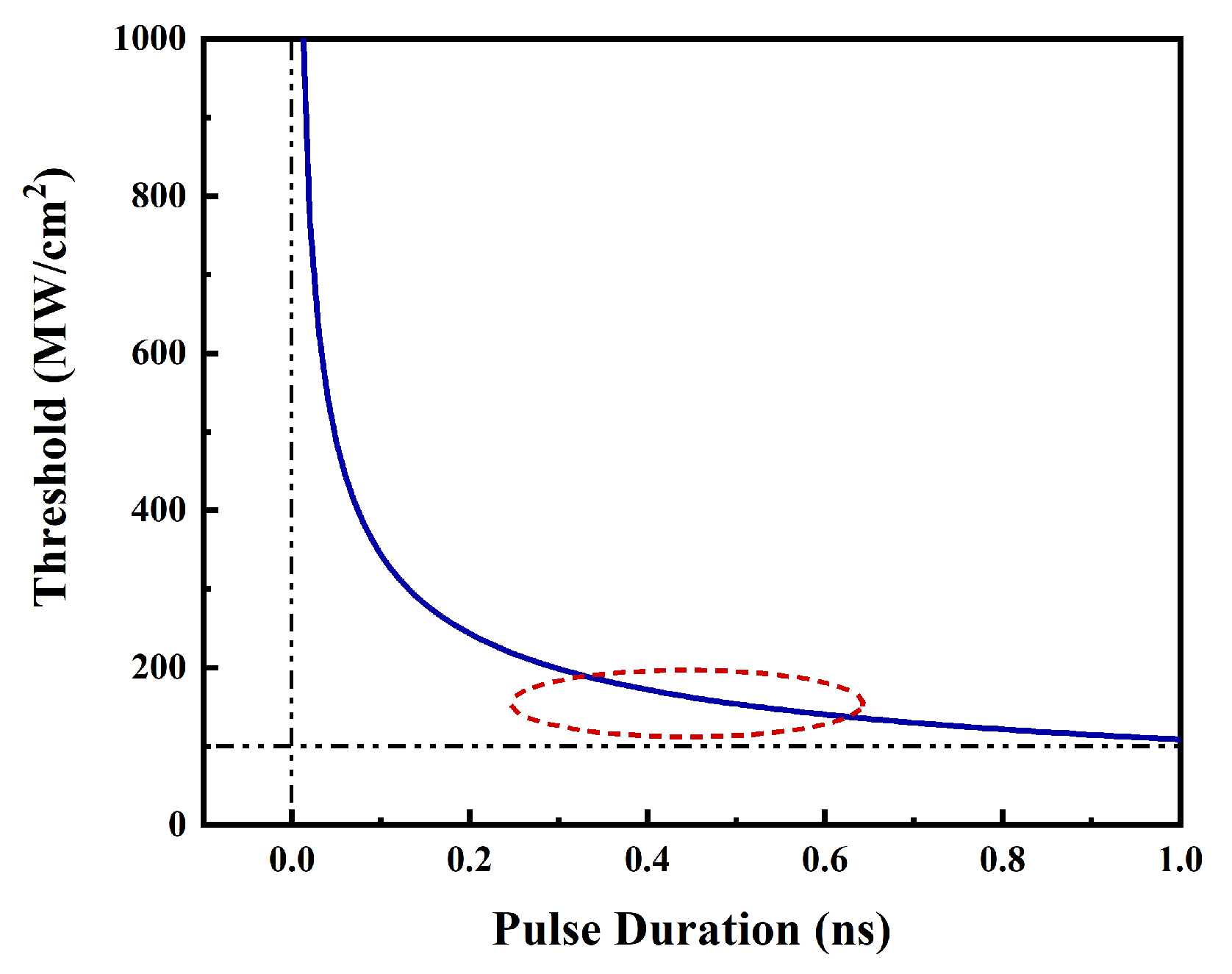
In
Figure 1, the relationship between the input pulse duration and the generation threshold determined through numerical simulation is illustrated. In the SRS pulse compression, the backward Stokes generated in the generator meets the pump light in the amplifier, and the Stokes generated in the generator is used as the seed light to extract the pump energy because the higher-order Stokes are stimulated by the accumulation of first-order Stokes energy to a certain extent. In addition, the existence of the higher-order Stokes inevitably consumes the first-order Stokes. The higher-order Stokes does not participate in the amplification process, and only the first-order Stokes extracts the pump energy to be compressed and amplified, causing a lower energy efficiency. To improve the energy efficiency of SRS pulse compression, a feasible method involves raising the threshold of first-order Stokes, and thus its energy accumulation cannot reach levels that would excite higher-order Stokes. As can be seen from the red dashed circle in
Figure 1, a substantial change occurs in the threshold when the input pulse duration is 0.6
or less. Therefore, to enhance the energy efficiency of the SRS, the input pulse duration should be shorter than 0.6
. With this adjustment, the intensity of the generated Stokes experiences a significant improvement, effectively fulfilling the objective of enhancing energy efficiency.
3. Experiment Setup
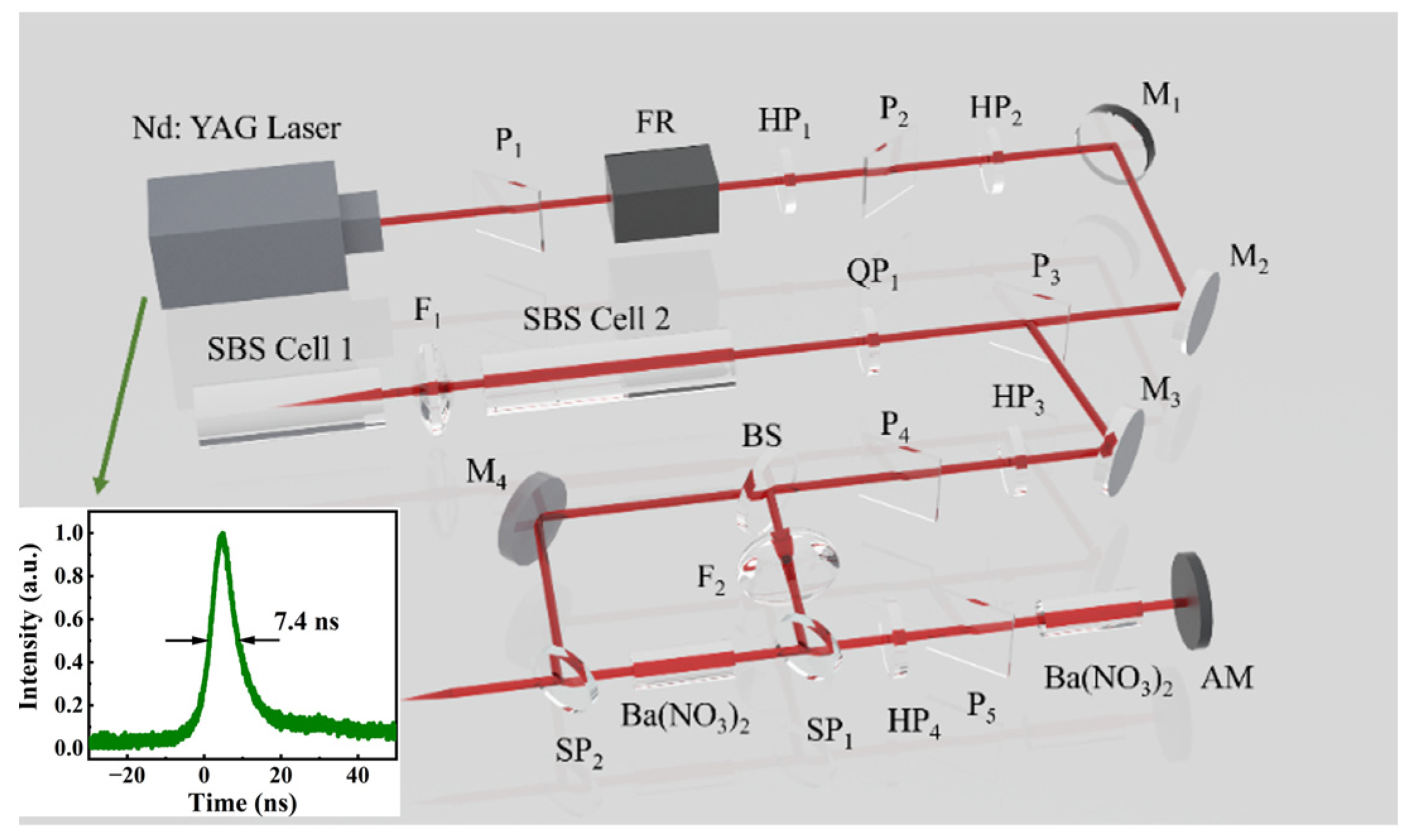
The experimental setup diagram of the SBS and SRS combined compression system is depicted in
Figure 2. The pump is a passively Q-switched Nd: YAG laser [
24], and its output is the Gaussian waveform with a wavelength of 1064
, a pulse duration of 7.4
and a beam quality factor of
= 1.2. P
1, P
2, FR and HP
1 form a spatial optical isolator. HP
2 and P
3 are combined to form an energy regulator that controls the pumping of energy into the SBS compression. In the current experiment, the pump pulse output is detected by the laser, and a time-domain waveform with a pulse duration of 7.4
is obtained. The details are illustrated in
Figure 2. The medium used in the SBS compression is FC-40 (
= 1.6
,
= 0.3
), and a compact double-cell structure is employed to output 28.6
of Stokes with a pulse duration of 580
at a pump energy of 35.2
. On this basis, SRS compression is conducted, and the SRS adopts a generation–amplification double-cell structure with a medium of Ba(NO
3)
2 crystal whose length is 5 cm (
= 11
,
= 0.4
). After being compressed by SBS, a portion of the output light is reflected by the beam splitter (BS) and focused by the lens (F
2) on the generator cell to generate backward Stokes, serving as seed light during the amplification process. However, the other portion is transmitted as the pump through the BS and then meets the Stokes seed in the amplifier through the half-wave plate (HP
4) and polarizer (P
5). The seed light extracts energy from the pump for compression and amplification, and the Stokes is ultimately output through the dichroic mirror (SP
2). Additionally, energy is recorded using an energy meter (OPHIR PE50BB-DIF-C and OPHIR NOVA II); pulse duration characteristics are measured using an ultrafast phototube (UPD-35-IR2-D, Alphalas; rise time < 35
, wavelength range: 800–1700
) combined with a digital oscilloscope (DPO71254C, Tektronix; bandwidth: 12.5
, sampling rate: 100
); and a beam quality analyzer (CCD, Dataray, Redding, CA, USA) is used to detect and explore the spatial profile of the beam.
4. Results and Discussion
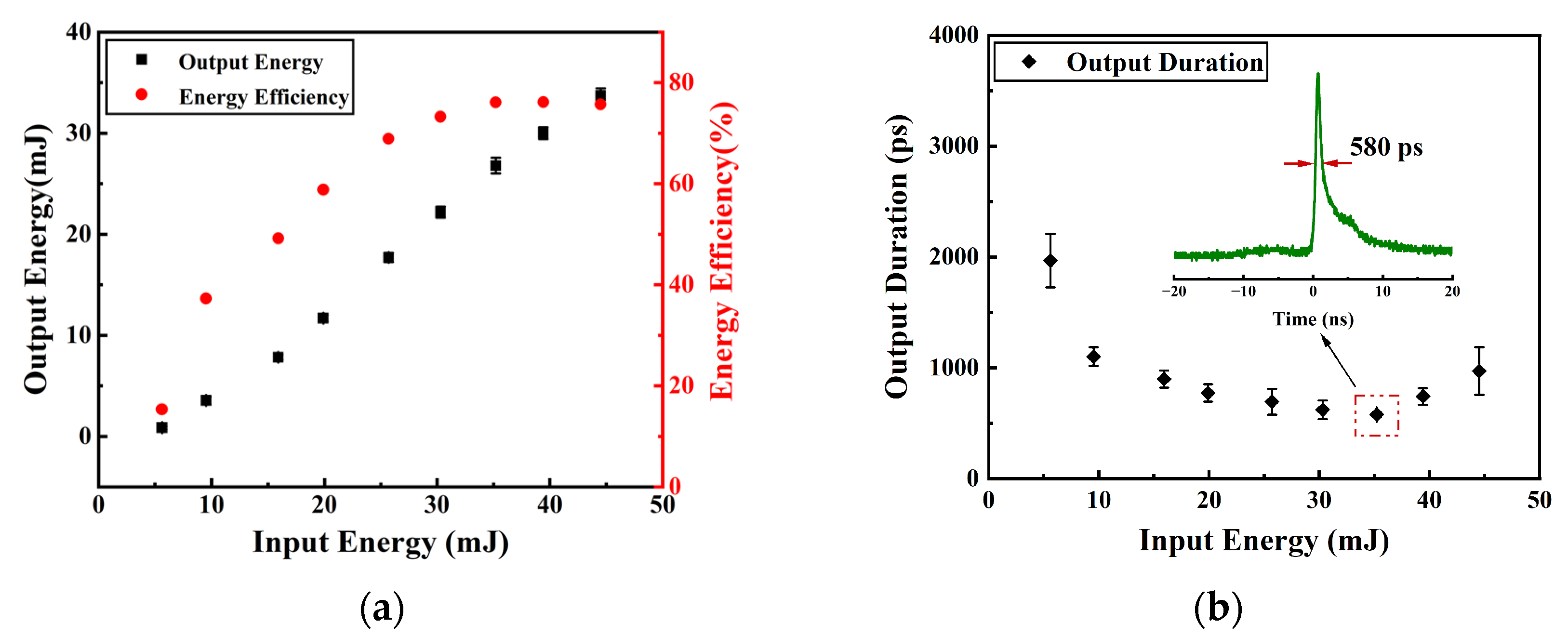
The output characteristics of SBS compression are measured. As shown in
Figure 3a, the output energy and energy efficiency are recorded simultaneously. With the increase in input energy, the output energy increases linearly and the corresponding energy efficiency initially rises rapidly at low input energy levels and later reaches a stable value. At the low energy range of 5–30
, with the increase in input energy, the energy efficiency exhibits a steep upward trend, and the pump energy extracted by seed light is compressed and amplified by SBS. When it is characterized by higher energy, the extraction speed decreases and the energy efficiency slowly increases. Then, the pumping energy extracted by Stokes seed light reaches a saturation point. Finally, the energy efficiency stabilizes at approximately 75%. The evolution of the output pulse duration in relation to the input energy is shown in
Figure 3b. With the increase in input energy, the output pulse duration first decreases to the minimum value and subsequently increases slowly. The reason for this phenomenon is that the Stokes leading edge absorbs pump energy to saturation, and then, with the continuous increase in input energy, the leading edge is in a saturated state and no longer absorbs energy, while the trailing edge absorbs energy and is amplified, resulting in a phenomenon in which the output Stokes pulse duration is widened. At a pump energy of 35.2
, the output Stokes pulse duration is 580
and the corresponding output energy is 26.8
.
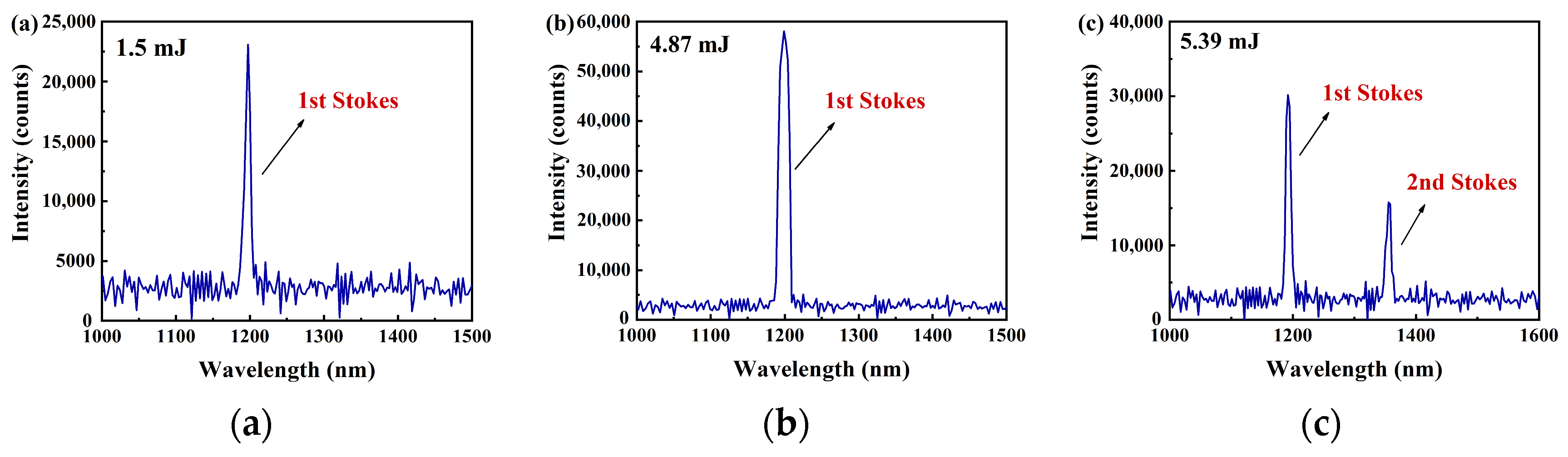
On this basis, the input characteristics of the SRS generator are determined. A stable output of Stokes is observed when the input energy reaches 1.5 . The generation of SRS is cascaded, where higher-order Stokes are directly excited by first-order Stokes after reaching a certain energy level. Therefore, the energy of the first-order Stokes is consumed subsequently by the generated high-order Stokes. Moreover, the first-order Stokes acts as the seed to extract pump energy during the amplification process of SRS, while the higher-order Stokes is not involved, further leading to the existence of high-order Stokes significantly affecting the energy efficiency of first-order Stokes. To improve the energy efficiency of the SRS generator, an effective method is to ensure that the high-order Stokes is not generated in the generator. The use of short pulses with a pulse duration of 580 as the input for SRS generator has a high generation threshold, which prevents the first-order Stokes energy from reaching the excitation level for high-order Stokes.
As displayed in
Figure 4, the spectrum of the Stokes output by the generator under various input energies was recorded, including values such as 1.5
, 4.87
and 5.39
. Only the first-order Stokes is present in
Figure 4a,b, while in
Figure 4c, the second-order Stokes appears at an energy of 5.39
. The maximum input energy used in the experiment for the generator is 4.87
. Only the first-order Stokes with a wavelength of 1198
is present under this condition.
In the experiment, the output pulse duration is detected by an ultrafast phototube connected to a digital oscilloscope with a bandwidth of 12.5
. As the theoretical detection limit of an oscilloscope is generally considered to be the reciprocal of the bandwidth, it can be concluded that the theoretical detection limit of the digital oscilloscope used in the experiment is 80
. Due to the theoretical detection limit, the rise time of the ultrafast photocell and the response time of the digital oscilloscope have a certain impact on the measured results. The actual pulse duration (
) output by SRS pulse compression is calculated according to Equation (6) [
25]:
where
is the result of the experiment;
refers to the rising time of the ultrafast photoelectric probe; and
denotes the response time of the digital oscilloscope. Based on the experimental measurement results, the actual pulse duration output by the generator and the amplifier is calculated according to the above formula.
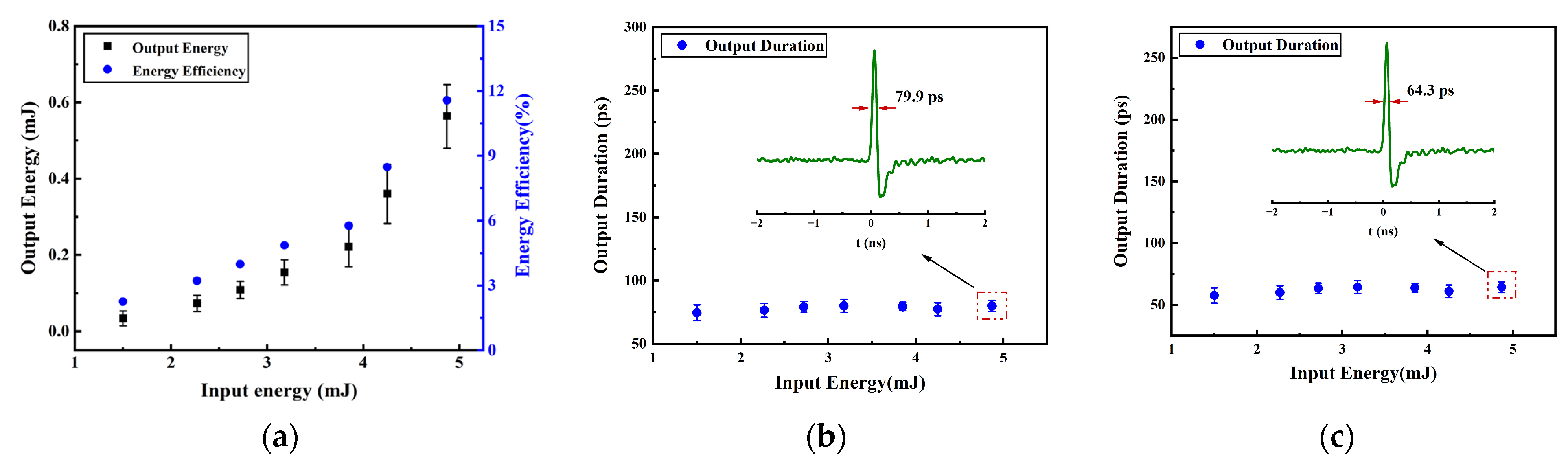
As shown in
Figure 5a, the output energy of the generator has been rapidly increasing with the rise in input energy, and the corresponding energy efficiency has also been increasing. With the increase in input energy, the energy of backward Stokes generated in the generator also increases. The output energy is 0.56
and the energy efficiency is 11.6%, while the input energy is 4.87
. As the actual output pulse duration is affected by the bandwidth of the oscilloscope and the photoprobe, the actual output pulse duration is obtained by subtracting the bandwidth of both from the pulse duration displayed by the oscilloscope. The measured and actual results of the generator are respectively shown in
Figure 5b,c. There is no significant fluctuation in the output pulse duration within the range of the input energy of the generator cell. As can be seen in
Figure 5b,c, the pulse waveforms of insets are classified into positive and negative signals. In general, it is shown that the positive signal values are the normal measured optical signals, and the negative signal values are the electromagnetic oscillation caused by a short falling edge of the pulse waveform. Therefore, the area with positive signal values is considered the pulse duration. When the input energy is 4.87
, the actual output pulse duration is 64.3
.
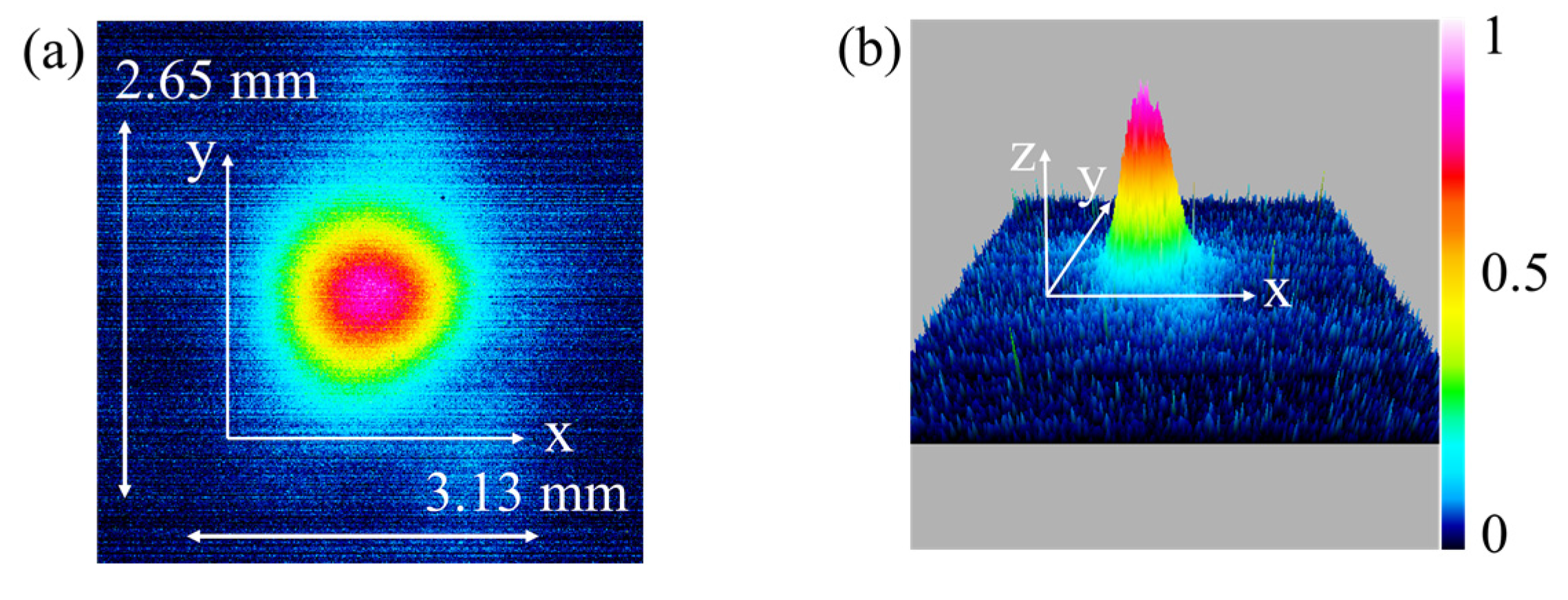
Figure 6 shows the spatial distribution pattern of the light beam output by the SRS generator. It is measured at a position of 3
after leaving the generating cell. The transverse diameter and longitudinal diameter of the spatial beam profile are respectively marked as 3.13 and 2.65
in
Figure 6a. The
z-axis in
Figure 6b only represents the intensity of light at varying positions. The color change on the right side of
Figure 6b indicates that the light intensity, in turn, shifts from blue to red (from weak to strong), and the corresponding relative intensity changes from 0 to 1. The spatial profile of the beam output by the generator features a well-defined Gaussian distribution.
The input energy of the SRS generator is fixed at 4.87
, with an output energy of 0.56
, an energy efficiency of 11.6% and an output pulse duration of 64.3
. The Stokes pulse generated in this case serves as the seed in the amplifier. The 580
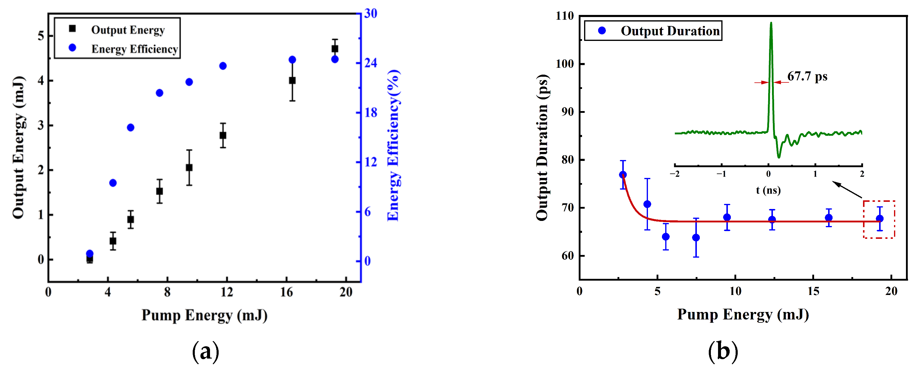
output by the SBS compression is taken as the pump in the SRS amplification process. The characteristics of the SRS amplifier are displayed in
Figure 7. The output energy increases continuously with the increase in pump energy, as shown in
Figure 7a. The energy efficiency first increases rapidly with the increase in pump energy, and, subsequently, it slows down while the extraction of pump energy by the Stokes seed gradually reaches saturation, ultimately stabilizing at around 24%. The evolution of the output pulse duration displayed by the oscilloscope is recorded in
Figure 7b. With the increase in pump energy, the output pulse duration first decreases at a fast speed, and then its change is inconspicuous. When the pump energy is 2.79
, the lower pump power limits the higher power seed from extracting energy. The pump power is already higher than the Stokes seed, while the pump energy reaches 4.35
. In this case, the Stokes seed can effectively extract energy from the pump, leading to further compression of the output pulse. As the energy further increases, the extraction gradually reaches saturation and the output pulse duration tends to stabilize. The illustration in
Figure 7b shows the time-domain waveform of the output pulse at an input energy of 19.26
. In this case, the output pulse duration is 67.7
, consistent with an output energy of 4.71
and an energy efficiency of 24.5%.
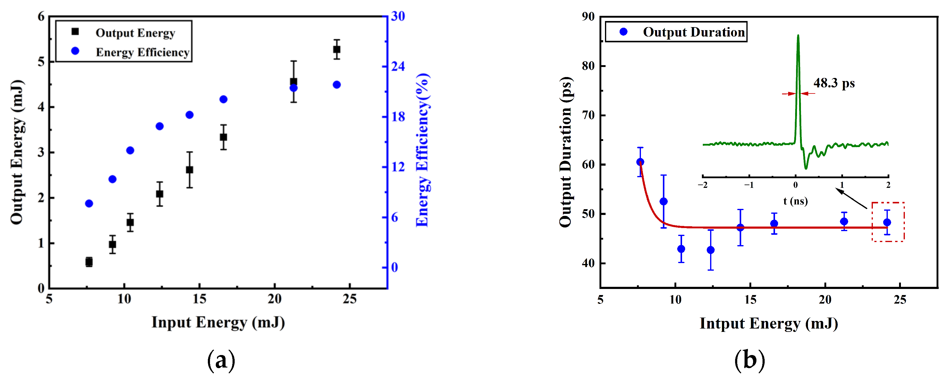
The characteristics of SRS compression are presented in
Figure 8.
Figure 8b illustrates the actual pulse duration, which is the pulse duration output by the oscilloscope minus the bandwidth influence of the oscilloscope and photoelectric probe. The horizontal axis indicates the total input energy of the combination of the SRS generator and the amplifier. A total output energy of 5.27
, an energy efficiency of 21.84% and an actual output pulse duration of 48.3
are finally obtained at an input energy of 24.13
.
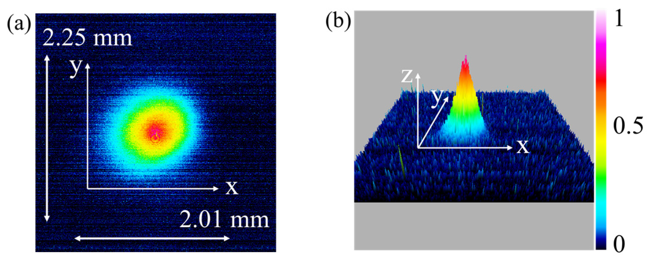
The spatial profile of the final output Stokes from the SRS system is collected, as shown in
Figure 9. It is measured at a position of 3
after leaving the generating cell. According to the observation, the transverse diameter and longitudinal diameter of the spatial profile section of the beam are respectively marked as 2.01 and 2.25
. The
z-axis in
Figure 9b only suggests the intensity of light at different positions. The color change on the right side of
Figure 9b indicates that the light intensity, in turn, shifts from blue to red (from weak to strong), and the corresponding relative intensity varies from 0 to 1. Compared with the spatial beam profile output by the SRS generator, the distribution of radiant intensity output by the SRS generator–amplifier is more concentrated on the laser spot center. Therefore, during the SRS process, the center of the beam undergoes higher compression and amplification than the edge of the beam, thus increasing the concentration of energy distribution. The beam quality is measured, and a beam quality factor M
2 of 1.3 is obtained.


 ,
, 