1. Introduction
Today, many applications, including fundamental science, industrial materials processing, and medicine, widely use continuous fiber lasers with powers in the range of several kW. The key components of these lasers are active single-mode fibers with a large mode area, which must have low bending losses to ensure the compactness of the lasers. Concurrently, research is ongoing in the area of passive single-mode optical fibers with a large mode area, which are crucial for delivering laser radiation over the required distance with the necessary beam parameters. A variety of microstructured optical fibers (MOFs), including photonic bandgap fibers [
1], Bragg fibers [
2], and leakage channel fibers (LCFs) [
3,
4,
5], can be used for these purposes, in addition to traditional optical fibers with a stepped refractive index profile.
A salient characteristic of leakage channel MOFs (LC MOFs) is the occurrence of non-zero loss levels for all modes, including fundamental modes. The geometrical structure of LC MOFs is relatively simple, which facilitates the search for optimal LC MOF parameters that ensure an effective single-mode regime at a large core diameter while providing low bending losses. The criterion for an efficient single-mode operation is low leakage losses (<0.1 dB/m) for two polarizations of fundamental modes (FMs) and simultaneously high leakage losses (>1.0 dB/m) for higher order modes (HOMs).
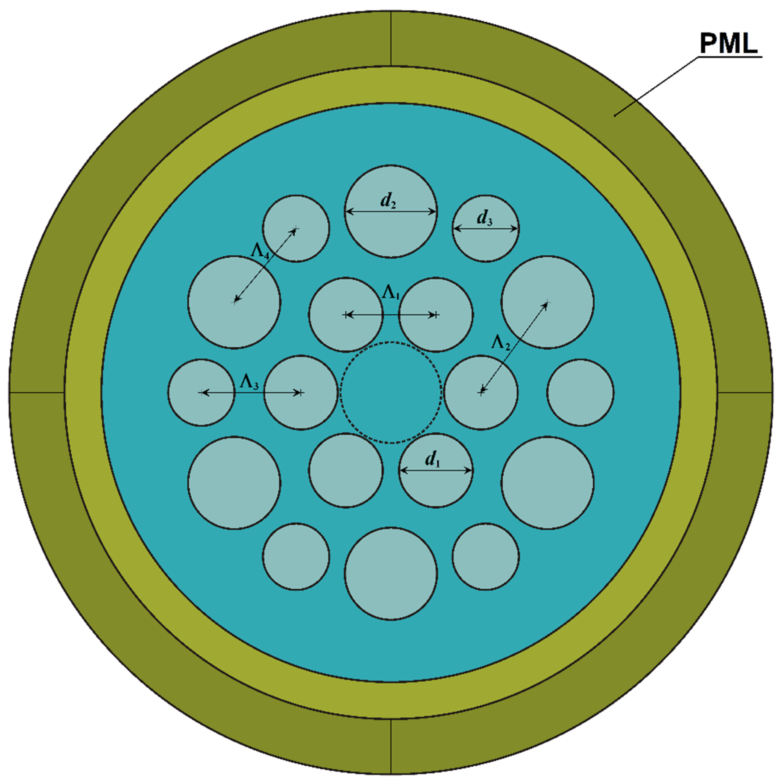
In previous proposals [
6,
7], we investigated an original design of all-glass LC MOFs with two layers of circular elements made of fluorine-doped silica glass with a reduced refractive index, different diameters, and different distances between the nearest elements. The distinctive feature of this design is the ring gap between the first and second layers of elements. It allows us to increase the leakage losses for higher-order modes relative to fundamental modes, providing an efficient single-mode regime. Our calculations have demonstrated that for this LC MOF with a core diameter of 20 μm and specific selected parameters, it is feasible to achieve the spectral range of the effective single-mode regime from 0.92 μm to 1.21 μm at a bending radius of 8 cm [
7]. The experimental studies of the fabricated LC MOFs demonstrated that the measured losses for a sample with a core diameter of 22.5 μm at a bending radius of 10 cm in the free coil were less than 0.1 dB/m in the wavelength range from 0.9 to 1.5 μm [
7]. It should be noted, however, that in order to achieve a single-mode regime with minimal bending losses in our studies, we had to use a coil with a radius of 10 cm instead of 8 cm as calculated for the model LC MOF structure. It was therefore essential to conduct a comprehensive theoretical (numerical) study of the bending properties of all-glass LC MOFs across a wide range of bending radii.
Previous research has examined bending losses in various optical fibers [
8,
9,
10], including LC MOFs [
11,
12]. The observed variations in the bending losses of these fibers have been attributed to the coupling of the fundamental core modes to the leaked cladding modes. No compelling physical evidence has been presented to support this hypothesis, except for the supposed coincidence of the real parts of their effective refractive indices (index-matched coupling [
13,
14]). However, the mere coincidence of the effective refractive indices of the core and cladding modes is not a compelling argument. These modes are localized in different parts of the optical fibers, specifically in the core and in the cladding, respectively. From a physical standpoint, the exact mechanism by which they could interact with each other, and thus be coupled, remains unclear. Notwithstanding, this hypothesis remains widely endorsed and has been accepted as fact until recently [
10].
The coupled-mode theory has been in widespread use for over five decades and has been applied to theoretical studies of distributed feedback lasers [
15], as well as to the modeling of various optical fiber gratings [
16,
17,
18]. All of these studies are characterized by the presence of longitudinal inhomogeneity in the investigated fibers, which, in fact, determines the coupling of modes. It is essential to emphasize that, as documented in a recently published paper [
19], coupled-mode theory is a phenomenological theory that relies on fitted coupling coefficients and is devoid of a foundational validation based on electromagnetic principles.
An interesting approach to mode control and tuning in anisotropic optical microresonators with whispering gallery modes (WGM) was put forth in [
20]. In these resonators, regular occurrences of anticrossings (and couplings) between different modes have been observed. However, the underlying physics of this phenomenon remains poorly understood, presenting a significant challenge for mode control and tuning. The prevailing view of WGMs as scalar modes obeying the scalar Helmholtz equation has contributed significantly to the uncertainty surrounding anticrossing behavior. The authors of [
20] have demonstrated that the anticrossings are intrinsic to the o- and e-modes due to the vectorial characteristics of Maxwell’s equations. A novel perturbative approach was employed, utilizing a strong localization of the modes in the vicinity of the resonator rim. The anticrossings were quantified using the electric field component
Ez and the magnetic field component
Hz as a pair of independent variables. The derived values of the avoidance gaps were experimentally confirmed in lithium niobate resonators.
A comprehensive theoretical investigation of anticrossing and mode coupling in a bent LC MOF, comparable to that conducted in reference [
20], appears to be quite challenging due to the complex geometrical structure involved. Nevertheless, Maxwell’s equations possess a fundamental character, providing the foundation for a significant portion of the software utilized in the field of numerical calculations. In our recent work [
21], we investigated how the spatial distributions of the electric field components of different modes change as the bending radius of the LC MOF is varied in the interval between 3 cm and 11 cm. By combining this analysis with standard parameters such as effective refractive indices, bending losses, and spatial intensity distributions of the modes, we were able to provide a more accurate and well-founded interpretation of the numerical results from a physical standpoint.
A detailed analysis revealed the necessity of considering three modes for each polarization to ensure accurate calculation of bending losses [
21]. These modes exhibit a complex spatial intensity distribution, with local maxima both in the LC MOF core and in the ring gap between the element layers. Therefore, these modes cannot be attributed to the fundamental core modes or to the leaked cladding modes; they are, in fact, LC MOF modes in general. Two pairs of these three modes are coupled in two different ranges of bending radii, specifically near 3.68 cm and near 5.95 cm. The dependences of the effective refractive indices of the modes exhibit a distinctive anticrossing behavior. The degree of coupling between the modes can be quantified by the difference in their effective refractive indices. The minimum of this difference at the corresponding bending radii indicates the maximum coupling of these modes in pairs, which indicates the resonant character of modes coupling.
It is crucial to underscore that the maximum coupling between modes in pairs is observed precisely at the bending radius where their spatial intensity distributions exhibit the greatest similarity. This is evidenced by the presence of similar local maxima in the core and in the ring gap. Furthermore, the spatial distributions of the electric field components
Ex are practically identical, both in terms of shape and in terms of absolute value, and this provides a compelling argument from a physical standpoint [
20]. Such a conclusion differs fundamentally from the index-matched hypothesis of coupling between the fundamental core modes and the leaked cladding modes [
8,
9,
10,
11,
12,
13,
14].
One of the important factors affecting the bending losses of optical fibers is the presence of a polymer coating. Theoretical and experimental investigations of macro bending losses for standard single-mode fibers have been performed in a number of papers [
22,
23,
24]. An interesting study has also been carried out in [
25], where the effect of polymer coating on losses in Bragg fibers has been investigated, but only in straight ones. In [
26], the losses in LC MOFs have been studied, also only for straight variants, but for different polymer coatings and for different diameters of the silica cladding.
This paper represents a continuation of our recent study, which was presented in [
21]. We performed a systematic and comprehensive analysis of the numerical results, employing the same approach as in a previous study.
In the present work, we present the results of a detailed theoretical (numerical) study of the bending properties of all-glass LC MOFs with polymer coating across a range of bending radii from 4.8 cm to 10 cm. In addition to the usual parameters, such as effective refractive indices, bending losses, and spatial intensity distributions, we have determined the spatial distributions of the electric field components of different modes. Furthermore, additional quantitative data have been determined, namely the integral values of the intensities in three separate regions of the LC MOF: the core, the ring gap, and the outer silica cladding. Additionally, integral values of the electric field components of different modes in the core and in the ring gap of the LC MOF have been determined. This has enabled us to provide a physically accurate interpretation of the numerical results.
One of the most striking contrasts between the results for the LC MOF with polymer coating and the uncoated LC MOF is the significant difference in all LC MOF parameters for two polarizations in the presence of a polymer coating. Furthermore, the analysis revealed that eight modes for each polarization must be taken into account to ensure accurate calculation of the bending losses for the LC MOF with polymer coating.
A second notable distinction between the LC MOF with a polymer coating and an uncoated LC MOF is the markedly disparate behavior of the effective refractive indices of the LC MOF modes when the bending radius is altered. In the case of an uncoated LC MOF, anticrossings were observed for two pairs of the three actual modes. In contrast, an LC MOF with a polymer coating displayed a multitude of crossings and anticrossings for various pairs of modes. In the case of the anticrossing behavior, the corresponding modes in pairs exhibit complex changes of their parameters within a very narrow bend radius range. This may be conventionally described as a quasi-resonant transformation of modes [
21]. In the case of the crossing behavior, the corresponding modes in pairs have a relatively low value of the overlap integral of the spatial distributions of the electric field components,
Ex or
Ey. It is important to note, however, that the dependence of the overlap integrals on the bending radius exhibits a striking similarity in form with regard to both the crossing behavior and the anticrossing behavior.
3. Calculation Results
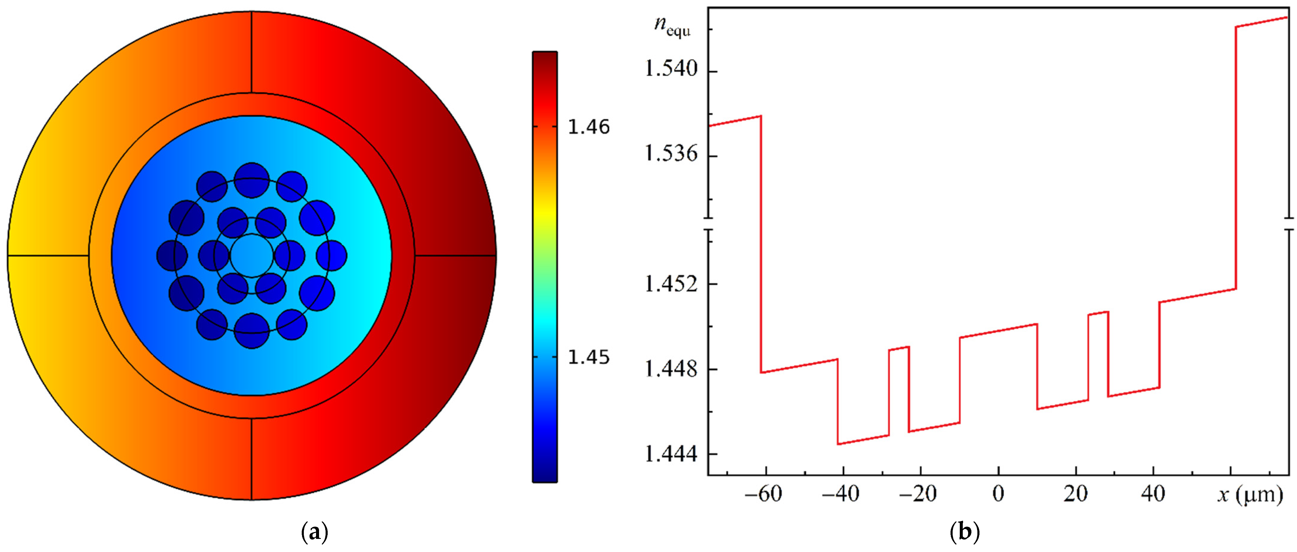
The MOF-18 characteristics were calculated numerically by the finite element method (FEM) with a cylindrical perfectly matched layer (PML) for a wavelength of 1.05 μm. The width of the PML layer was determined by the COMSOL 6.0 software algorithm, as described in the package manual, “Leaky Modes in a Microstructured Optical Fiber”, for each bending radius and appropriate effective refractive index range.
For the sake of convenience, the modes polarized along the x-axis and along the y-axis have been denoted by the numbers 1 and 2, respectively. Eight modes for each polarization must be considered, and their effective refractive indices exhibit complex dependencies on bending radius. Accordingly, the three strongest modes were denoted by letters “a”, “b”, and “c”, in descending order of the real part of their effective refractive indexes for a bending radius of R = 10 cm. The five relatively weaker modes were denoted by letters “d”, “e”, “f”, “g”, and “h”, in descending order of the real part of their effective refractive indexes and simultaneously in descending order of the bending radius.
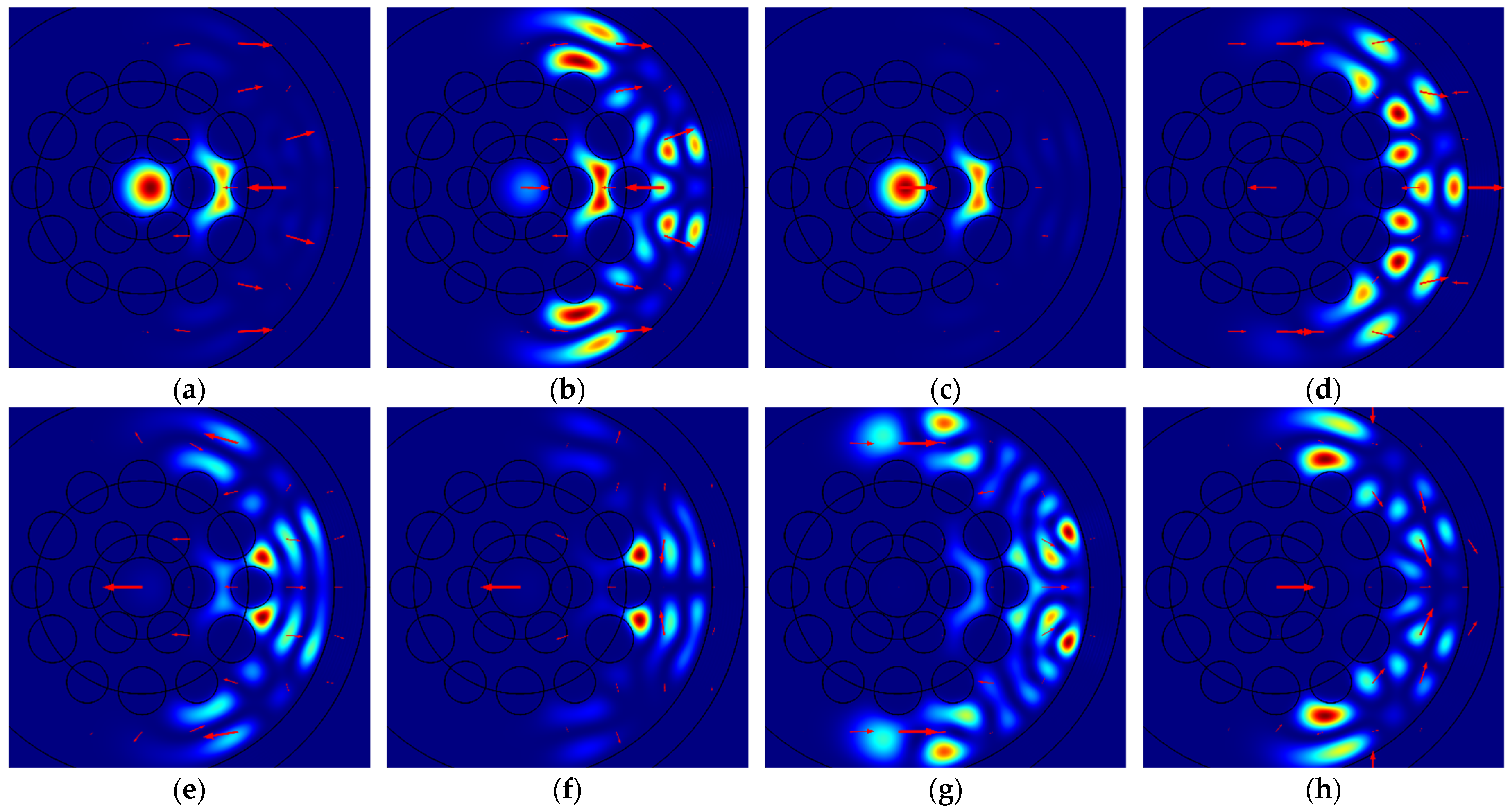
Figure 3 illustrates the spatial intensity distributions of different modes polarized along the
x-axis for specific bending radii
R: (a) Mode 1a for
R = 5.92 cm; (b) Mode 1b for
R = 5.98 cm; (c) Mode 1c for
R = 5.88 cm; (d) Mode 1d for
R = 8.05 cm; (e) Mode 1e for
R = 6.55 cm; (f) Mode 1f for
R = 6.15 cm; (g) Mode 1g for
R = 6.80 cm; and (h) Mode 1h for
R = 5.60 cm. The red arrows indicate the direction and relative magnitude of the electric field.
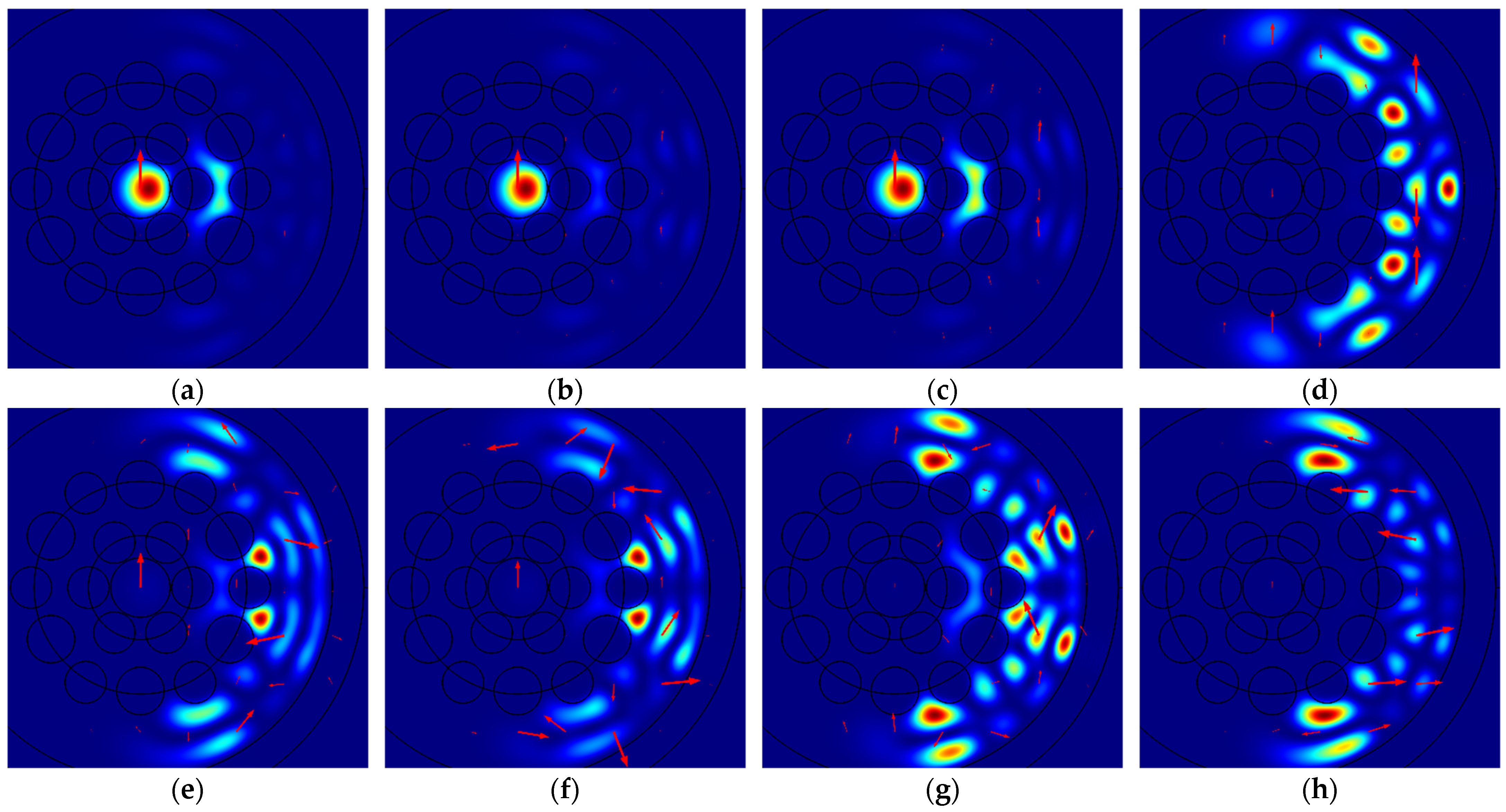
Figure 4 illustrates the spatial intensity distributions of different modes polarized along the
y-axis for specific bending radii
R: (a) Mode 2a for
R = 6.00 cm; (b) Mode 2b for
R = 5.90 cm; (c) Mode 2c for
R = 5.81 cm; (d) Mode 2d for
R = 8.05 cm; (e) Mode 2e for
R = 6.50 cm; (f) Mode 2f for
R = 6.30 cm; (g) Mode 2g for
R = 6.70 cm; and (h) Mode 2h for
R = 5.55 cm. The red arrows in this and the following figures, where present, indicate the direction and relative magnitude of the electric field.
As illustrated in
Figure 3 and
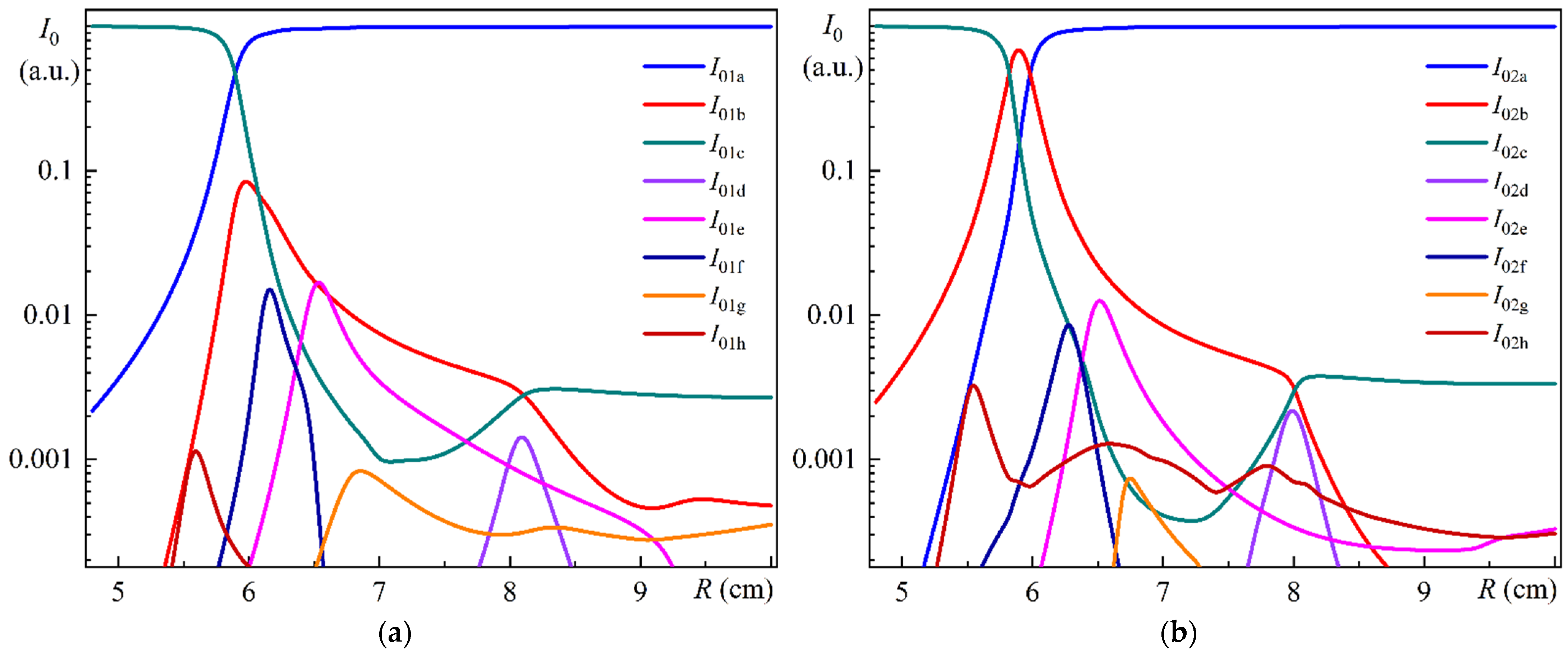
Figure 4, the intensity of five relatively weaker modes, denoted by letters “d”, “e”, “f”, “g”, and “h”, is very low in the core of the MOF-18, rendering it invisible under the ordinary color scheme. Information regarding the non-zero intensity of these modes can be obtained from the red arrows, which indicate the direction and relative magnitude of the electric field. For a quantitative comparison of the intensities of different modes, the integral intensities of these modes in the core of MOF-18 have been used, with the values being normalized to the sum of the intensities of all corresponding modes.
Figure 5a illustrates the dependences of the relative integral intensities of Modes 1a–h on the bending radius of the MOF-18.
Figure 5b illustrates the dependences of the relative integral intensities of Modes 2a–h on the bending radius of the MOF-18.
As illustrated in
Figure 5a,b, the intensities of five relatively weaker modes, denoted by letters “d”, “e”, “f”, “g”, and “h”, are less than approximately 1% of the sum of the intensities of all corresponding modes. It is nevertheless important to consider all these modes in order to correctly describe the calculated results. Consequently, during the calculations, the integral intensities of the modes were estimated for each particular bending radius, and those exceeding a specified threshold value were selected for further analysis. It is also worth noting that the values of bending radii
R selected for
Figure 3 and
Figure 4 correspond approximately to the maximum values of integral intensities for relatively weaker modes and to specific radii for the three strongest modes.
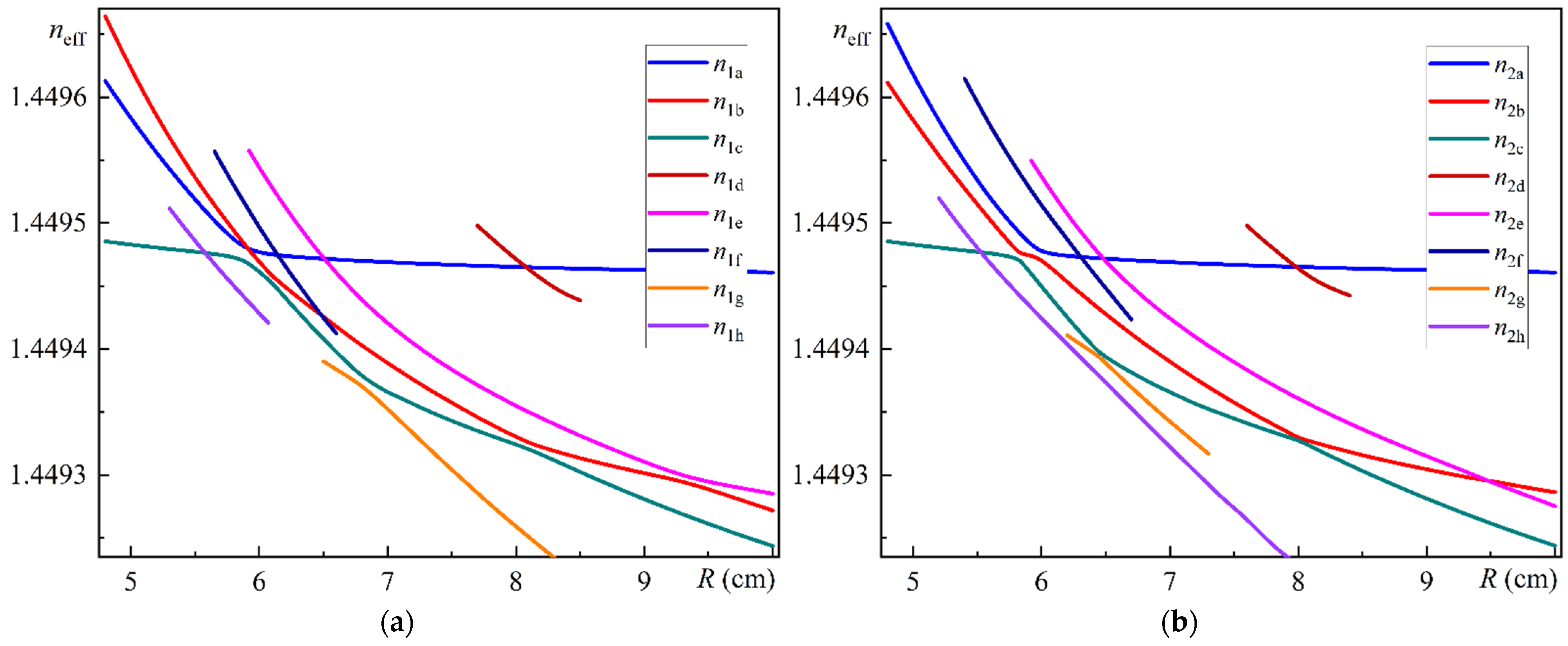
Figure 6a illustrates the dependences of the effective refractive indices of MOF-18 Modes 1a–h on the bending radius
R.
Figure 6b illustrates the dependences of the effective refractive indices of MOF-18 Modes 2a–h on the bending radius
R.
As can be seen in
Figure 6a,b, there are notable differences in the dependences of the effective refractive indices of MOF-18 modes polarized along the
x-axis and along the
y-axis. One of the most striking differences is the behavior of the dependences for Modes 1a and 1b in comparison to the behavior of the dependences for Modes 2a and 2b. In the former case, these dependences intersect at the bending radius
R = 5.90 cm, whereas in the latter case, there is a typical anticrossing behavior with a minimum of refractive index differences at the bending radius of 5.98 cm. A directly opposite pattern is observed for the behavior of the dependences for Modes 1b and 1e compared to Modes 2b and 2e. In the first case, a typical anticrossing behavior is observed with a minimum of the refractive index difference at a bending radius of 9.35 cm, whereas in the second case, their dependencies intersect at a bending radius of
R = 9.50 cm.
In general, the dependencies of the effective refractive indices of the MOF-18 modes on the bending radius have a number of crossings and anticrossings, which raises the question of their influence on the mode coupling at the corresponding bending radii.
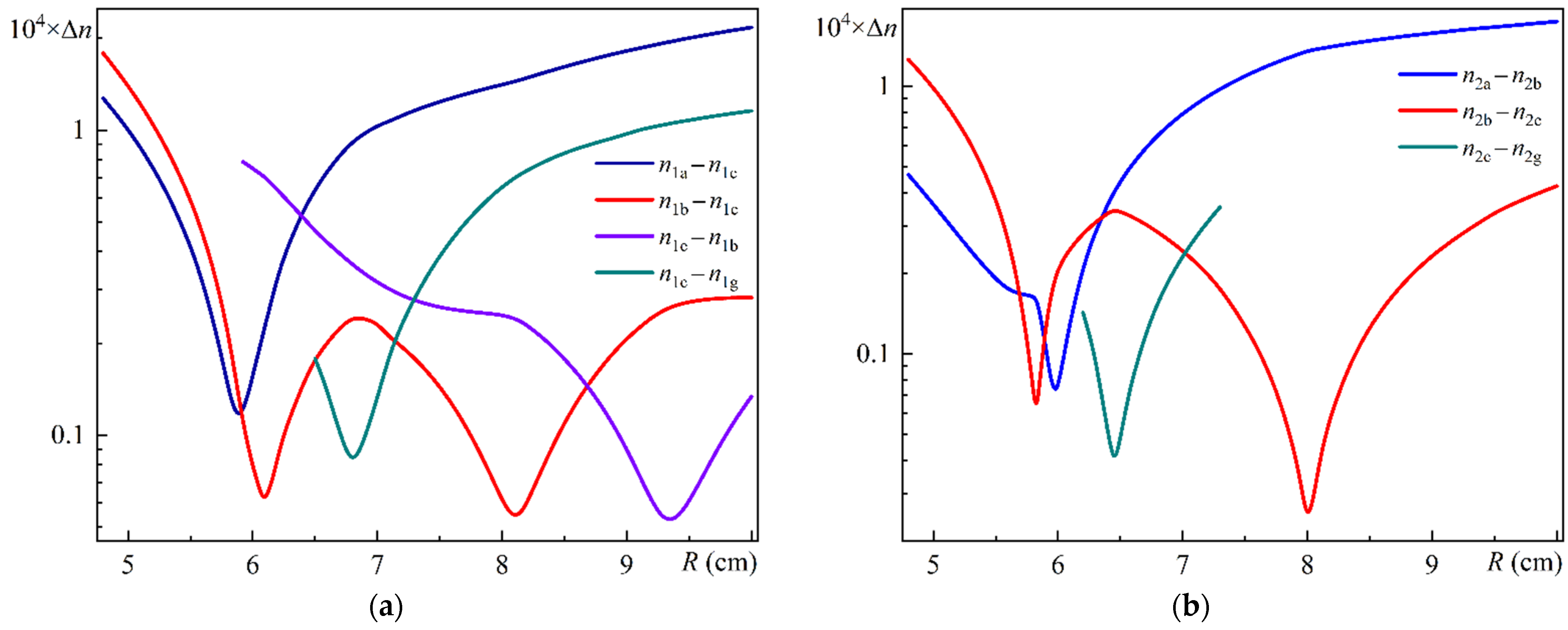
Figure 7a shows the differences in effective refractive index for different MOF-18 mode pairs polarized along the
x-axis vs. bending radius
R;
Figure 7b shows the differences in effective refractive index for different MOF-18 mode pairs polarized along the
y-axis vs. bending radius
R.
As can be seen from the comparison of these figures, the minimum values of the effective refractive indices for modes polarized along the y-axis are significantly, approximately by a factor of 2, smaller than for modes polarized along the x-axis (taking into account the different scale along the y-axis for these figures). It is also clear that the above dependencies for the modes polarized along the y-axis have a narrower range of bending radius in which significant changes occur. Although it is difficult to draw any significant conclusions about the nature of the mode coupling from these dependencies, it does raise the question of the need for further, more detailed studies.
In order to conduct the studies in question, two pairs of Modes, 2b and 2c and 1a and 1d, were selected as objects for detailed investigation.
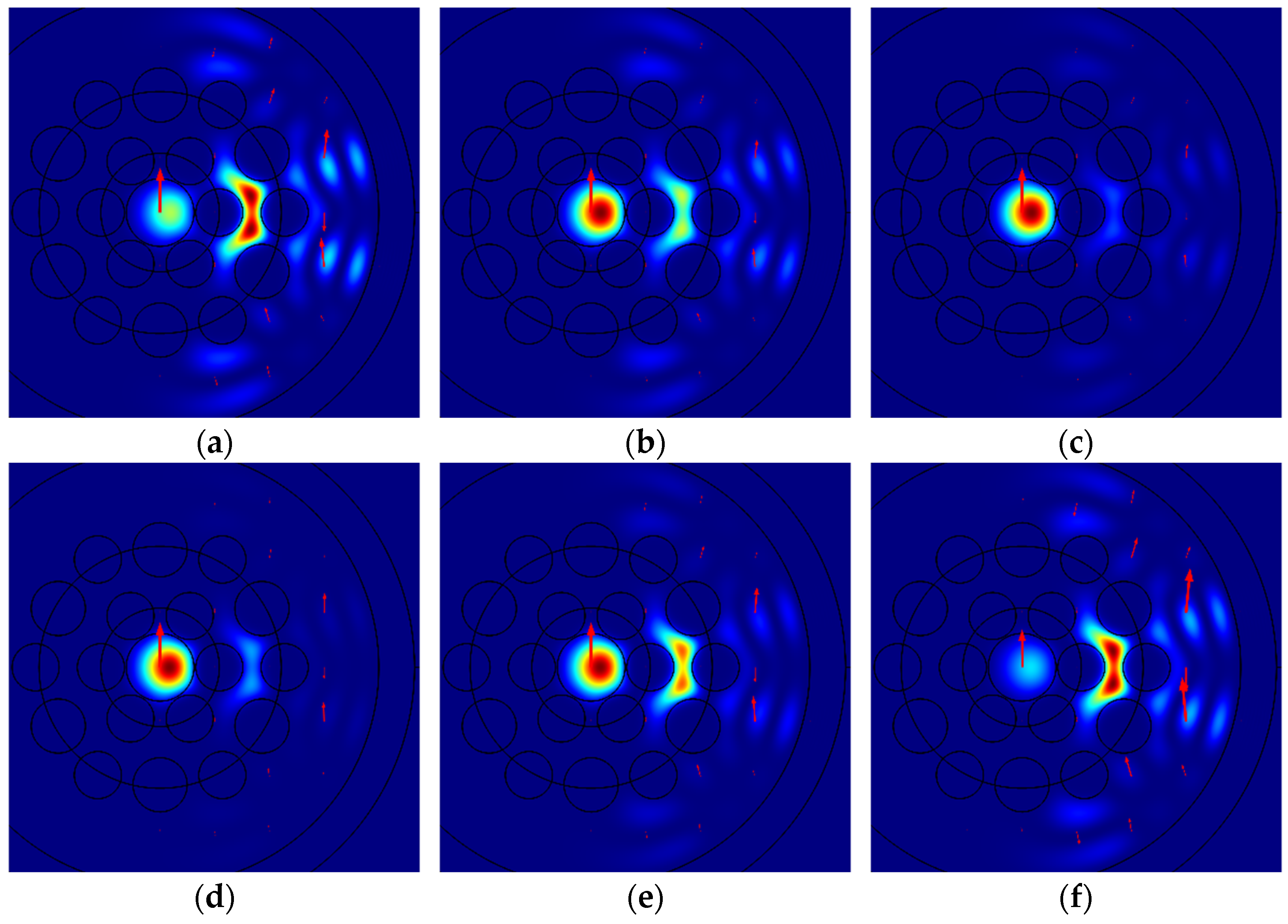
Figure 8 illustrates the spatial intensity distributions of Mode 2b for different bending radii: (a) 5.77 cm; (b) 5.82 cm; (c) 5.87 cm; and the spatial intensity distributions of Mode 2c for the same bending radii: (d) 5.77 cm; (e) 5.82 cm; (f) 5.87 cm.
As illustrated in
Figure 8b,e, Mode 2b and Mode 2c exhibit a striking similarity in their spatial intensity distributions for a bending radius of 5.82 cm. This similarity is evident throughout the entire range of regions of MOF-18, including the core, the ring gap, and the outer silica cladding. As illustrated in
Figure 7b, the bending radius of 5.82 cm corresponds to the minimum of the difference of effective refractive indexes for Modes 2b and 2c. The minimum of this difference indicates the maximum coupling of these modes, which indicates the resonant character of modes coupling. Thus, the maximum coupling between Modes 2b and 2c occurs precisely when their spatial intensity distributions are maximally close and contain similar local maxima in the core, ring gap, and outer silica cladding. This is consistent with our results for MBC-18 without polymer coating [
21], but fundamentally different from the outdated index-matched coupling hypothesis of coupling between the fundamental and the cladding modes [
13,
14].
As shown in
Figure 8a, for a bending radius of 5.77 cm, the intensity of mode 2b in the core of MOF-18 becomes smaller. Conversely, as shown in
Figure 8d, the intensity of mode 2c in the ring gap of MOF-18 becomes smaller for this bending radius. A similar picture is observed for a bending radius of 5.87 cm, but with the modes 2b and 2c reversed (see
Figure 8c,f). Since these changes occur within a very narrow bend radius range, they can be conventionally described as a quasi-resonant transformation of modes.
As previously stated, a comprehensive theoretical investigation of mode coupling in a bent MOF-18, analogous to that observed in [
20], is a challenging undertaking. Nevertheless, the spatial distributions of the electric field components of different modes offer valuable insights into these phenomena. For illustrative purposes, we have selected the electric field components
Ey for Mode 2b and Mode 2c of MOF-18 at a range of bending radii, identical to those employed in
Figure 8.
Figure 9 shows the spatial distributions of the electric field components
Ey of Mode 2b for different bending radii: (a) 5.77 cm; (b) 5.82 cm; (c) 5.87 cm; and also, the spatial distributions of the electric field components
Ey of Mode 2c for the same bending radii: (d) 5.77 cm; (e) 5.82 cm; (f) 5.87 cm. Legends for these figures are given in V/m.
As illustrated in
Figure 9b,e, the spatial distributions of electric field components Ey for Modes 2b and 2c of MOF-18 are essentially identical at the bending radius of 5.82 cm, both in terms of shape and in terms of absolute value. The authors of [
20] suggested that the coupling between the different WGMs they studied is solely due to the boundary conditions of their components, which are integral parts of Maxwell’s equations. Therefore, it may be assumed that the observed agreement of the spatial distributions of the electric field components
Ey for Modes 2b and 2c of MOF-18 indicates the maximum coupling of these modes at the given bending radius of 5.82 cm.
When the bending radius differs from 5.82 cm, discrepancies arise in the spatial distributions of the electric field components
Ey for Modes 2b and 2c (see
Figure 9a,c,d,f). The overlap integral of the spatial distributions of the electric field components
Ey for Modes 2b and 2c may provide quantitative insights into the coupling of these modes for varying bending radii. Moreover, this integral may prove more informative than the difference of effective refractive indexes for these modes, which merely indicates the presence of mode coupling. Furthermore, it may provide a more compelling physical confirmation of the coupling of the corresponding modes, in accordance with the findings of [
20]. It is also crucial to highlight that the spatial distributions of the electric field components
Ey for Modes 2b and 2c contain significantly more detailed information about these modes than, for example, their spatial intensity distributions. This can be observed by comparing
Figure 8 and
Figure 9.
As for the pair of Modes 1a and 1d for the bending radius range from 7.97 cm to 8.17 cm, their spatial intensity distributions can provide significantly less information than for Modes 2b and 2c. This is due to the fact that in this range of bending radii, the relative intensity of Mode 1a practically does not change and is close to 1, while for Mode 1d it is difficult to detect any changes since its intensity in the core is practically invisible even for a bending radius of 8.05 cm (see
Figure 3d and
Figure 5b). Therefore, we have limited ourselves to the spatial distribution of the electric field component
Ex for Mode 1d.
Figure 10 shows the spatial distributions of the electric field components
Ex of Mode 1d for different bending radii: (a) 7.97 cm; (b) 8.07 cm; (c) 8.17 cm. Legends for these figures are given in V/m. The two main conclusions that can be drawn from
Figure 10 are as follows: firstly, there is a clear similarity between the spatial distribution of the electric field components
Ex of Mode 1d in the core of MBC-18 and that of the classical fundamental mode; secondly, there is a noticeable difference in the magnitude of this electric field, which reaches its maximum value at the bending radius of 8.07 cm. This coincides with the bending radius where the dependences of the effective refractive indices of Modes 1a and 1d intersect each other (see
Figure 6a).
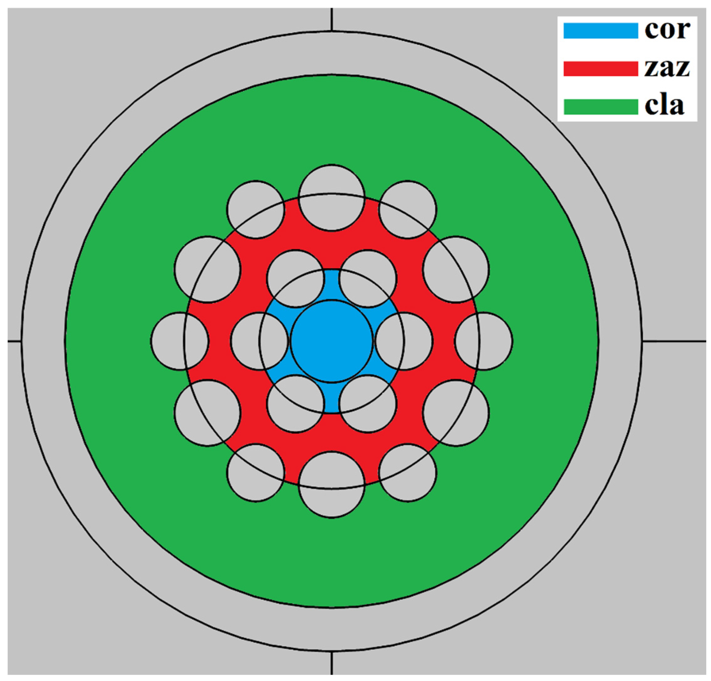
To provide a more detailed and quantitative analysis of the transformation process of some MOF-18 modes when the bending radius is altered, we calculated the integral intensities of Modes 1a, 1b, and 1c in distinct regions of MBC-18: the core, the ring gap, and the outer cladding.
Figure 11 illustrates a schematic division of the MOF-18 cross-section into distinct regions: the core (cor), indicated in blue; the ring gap (zaz), indicated in red; and the outer silica cladding (cla), indicated in green.
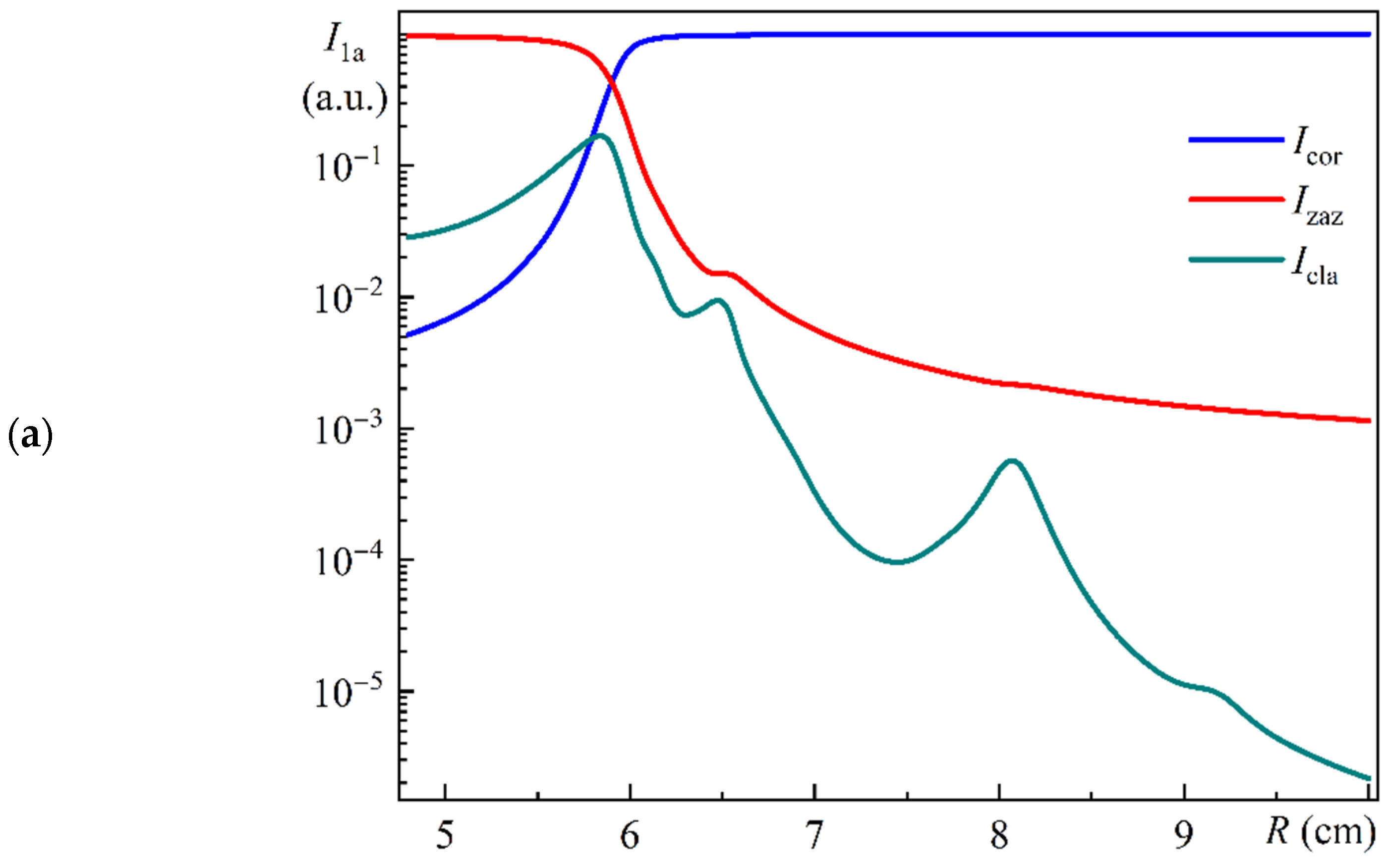
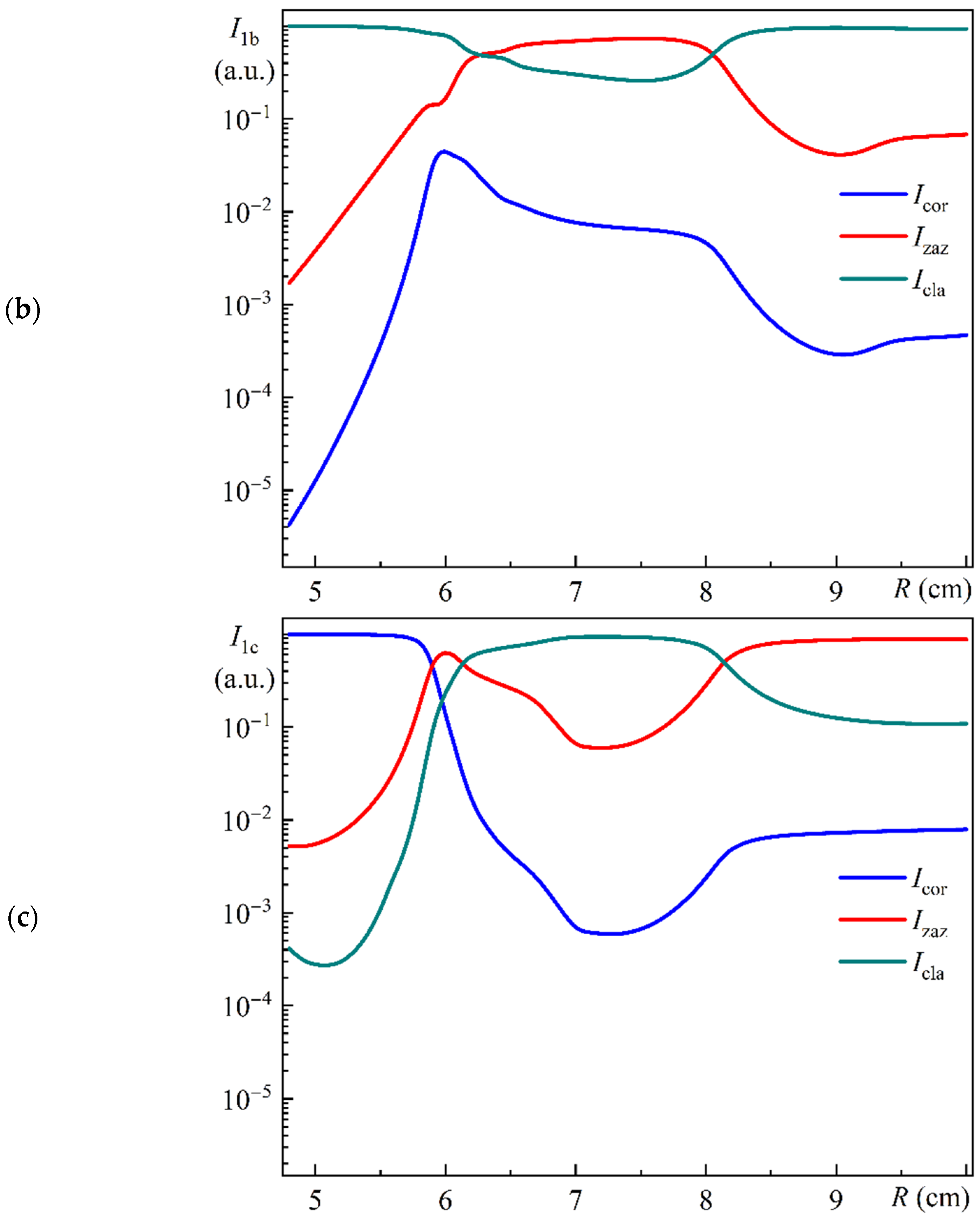
Figure 12 illustrates the dependence of the relative integral intensities of Modes 1a (a), 1b (b), and 1c (c) in the core (
Icor), in the ring gap (
Izaz), and in the cladding (
Icla) on the bending radius. All of these values have been normalized by the sum for the corresponding mode.
Figure 12a–c illustrate notable discrepancies in the behavior of Modes 1a, 1b, and 1c within the specified radius range.
Figure 12a,b illustrate that the relative intensities of Modes 1a and 1b in the core, in the ring gap, and in the cladding of MOF-18 exhibit a variation of approximately six orders of magnitude within the selected radius range.
Figure 12c illustrates that the relative intensities of Mode 1c in the core, in the ring gap, and in the cladding of MOF-18 vary by approximately four orders of magnitude in the selected radius range.
From
Figure 12a, we can see that for a bending radius greater than 6.20 cm, the relative intensity of Mode 1a in the core is greater than 95%, and for a bending radius greater than 6.57 cm, the relative intensity of Mode 1a in the core is greater than 98%. It can be stated with a considerable degree of accuracy (95% or 98%) that for these conditional intervals of bending radius, Mode 1a is in close accordance with the fundamental core mode, that is, the LP
01 mode polarized along the
x-axis.
From
Figure 12c, we can see that for a bending radius less than 5.60 cm, the relative intensity of Mode 1c in the core is greater than 95%, and for a bending radius less than 5.50 cm, the relative intensity of Mode 1c in the core is greater than 98%. It can be stated with a considerable degree of accuracy (95% or 98%) that for these conditional intervals of bending radius, Mode 1c is in close accordance with the fundamental core mode, that is, the LP
01 mode polarized along the
x-axis.
From
Figure 12b, we can see that for a bending radius of 5.98 cm, the relative intensity of Mode 1b in the core reaches a maximum value of about 4.5% of the total intensity.
It should be emphasized that these values are somewhat different from those shown in
Figure 5a, since they are completely different parameters. For
Figure 5a, the integral intensities were calculated only inside the circular core with diameter
Dcore. This was due to the requirement of determining the leakage losses for radiation entering the MOF-18 using a conventional single-mode fiber with the same core diameter
Dcore. Furthermore, the normalization of the integral intensities for
Figure 5a was conducted using the totality of the integral intensities for the eight corresponding modes. As an illustration, the resulting relative intensity of Mode 1b for a bending radius of 5.98 cm was determined to be 8.5%.
As previously stated, the overlap integral of the spatial distributions of the electric field components,
Ex or
Ey, for different mode pairs may provide quantitative insights into the coupling of these modes. Furthermore, it may provide a more compelling physical confirmation of the coupling of the corresponding modes, in accordance with the findings of [
20]. The direct calculation of the overlap integrals is a relatively time-consuming process. To streamline the process, we employed a straightforward product of the integral values of the corresponding electric field components over two regions of MBS-18: the core and the ring gap. Given that these distributions are similar in shape, this approach allows us to approximate the overlap integrals with a high degree of accuracy.
In addition to
Figure 9, we calculated the product of the integral values of the spatial distributions of the electric field components
Ey of Modes 2b and 2c:
Ey2b ×
Ey2c. Also, in addition to
Figure 10, we calculated the product of the integral values of the spatial distributions of the electric field components
Ex of Modes 1a and 1d:
Ex1a ×
Ex1d.
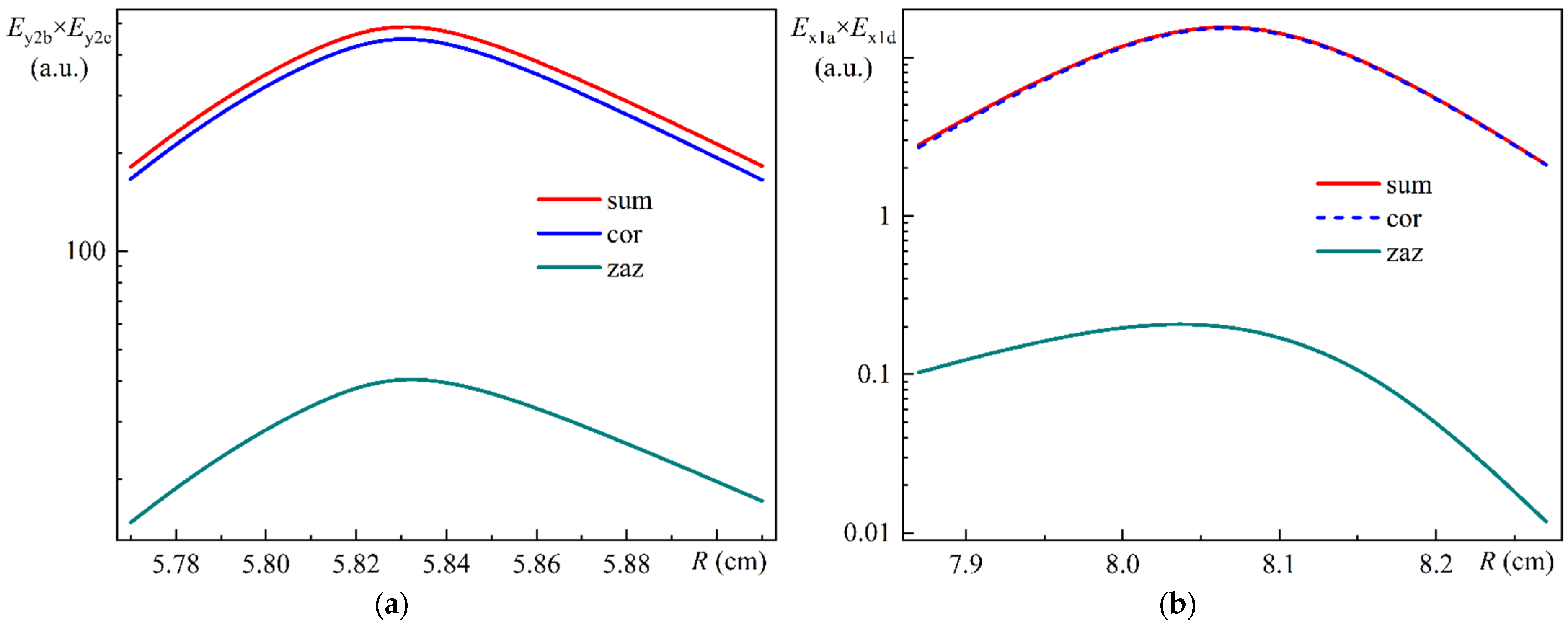
Figure 13a illustrates the relative values of the overlap integral of the electric field components
Ey of Modes 2b and 2c in the core (cor), in the ring gap (zaz), and in total (sum) as a function of the bending radius.
Figure 13b illustrates the relative values of the overlap integral of the electric field components
Ex of Modes 1a and 1d in the core (cor), in the ring gap (zaz), and in total (sum) as a function of the bending radius.
As can be seen in
Figure 13a,b, the dependences of the overlap integrals on the bending radius exhibit a remarkable similarity in form, yet their absolute values differ by a factor of about 25. It is worth noting that for
Figure 13a,b, the proportionality coefficients were selected to be identical. We now return to
Figure 6a,b, which illustrate the dependencies of the effective refractive indices of the MOF-18 modes on the bending radius, which exhibits a number of crossings and anticrossings. For the purpose of a detailed investigation of the anticrossing behavior, Modes 2b and 2c have been selected as objects of study. Similarly, Modes 1a and 1d have been selected for detailed investigation of the crossing behavior. Based on this particular example, we can tentatively conclude that in the case of anticrossing behavior, the overlap integral is significantly larger than in the case of crossing behavior.
We now turn to the problem of determining the losses for radiation that is polarized along the x-axis or along the y-axis and enters the MOF-18 segment of length L and bending radius R. For the sake of simplicity, we will assume that the radiation entering MOF-18 is that of a single-mode optical fiber with a pure silica glass core. This fiber has the same core diameter (Dcore) and bending radius (R) and is spliced with MOF-18 and wound together with it on a coil. In accordance with the accepted notations, the fundamental mode of this fiber polarized along the x-axis is designated as Mode 1, representing the LP01 mode polarized along the x-axis. Similarly, the fundamental mode of the fiber polarized along the y-axis is Mode 2, representing the LP01 mode polarized along the y-axis.
For simplicity, we assume that the spatial intensity distributions of Modes 1 and 2 have the same form as the spatial intensity distributions of Modes 1i and 2i (i = a ÷ h) in the core of MOF-18, differing only in magnitude. In general, it is necessary to use the integral of the overlap of the spatial intensity distributions of corresponding modes to calculate the transition of intensity between fibers.
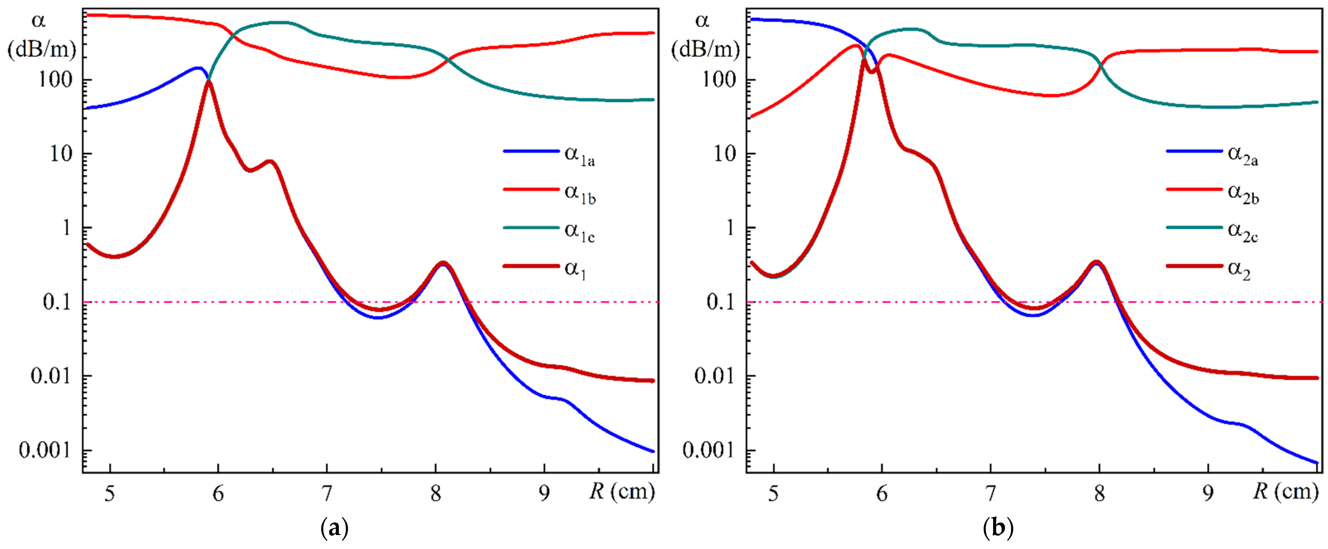
Figure 14a illustrates the calculated dependence of the leakage losses α
1a, α
1b, and α
1c of Modes 1a, 1b, and 1c on the bending radius.
Figure 14b illustrates the calculated dependence of the leakage losses α
2a, α
2b, and α
2c of Modes 2a, 2b, and 2c on the bending radius. It should be noted that the calculated leakage losses of relatively weaker Modes 1
i and 2
i (
i = d ÷ h) are of the order of 250 to 900 dB/m in the entire bending radius range. For the sake of simplicity, their dependencies on
Figure 14a,b have been omitted. Furthermore,
Figure 14a,b show a 0.1 dB/m loss level, which serves to identify the edge of the single-mode range.
To provide a quantitative description of losses for radiation entering MOF-18, we utilized the integrated intensities of Modes 1
i and 2
i (
i = a ÷ h) within the MOF-18 core, normalized by their sum, as illustrated in
Figure 5a,b. It is evident that for each specific bending radius, the incoming radiation polarized along the
x-axis or along the
y-axis is distributed, respectively, between Modes 1
i or 2
i (
i = a ÷ h) in proportion to their intensities in the core, as illustrated in
Figure 5a,b, respectively. Subsequently, as the radiation propagates along a segment of MOF-18 of length
L, the intensity in each of these modes will attenuate in accordance with their respective inherent losses.
Consequently, the overall intensities of Mode 1 and 2 are the sum of Modes 1i and 2i (i = a ÷ h) at the output of the MOF-18 segment with a length of L (which is also spliced with the aforementioned single-mode optical fiber and wound together with the MOF-18 on the coil). In accordance with standard practice, the losses for Modes 1 and 2 can be conventionally determined using the standard expression for losses in decibels per meter.
Figure 14a illustrates the final loss α
1 for radiation polarized along the
x-axis, while
Figure 14b illustrates the final loss α
2 for radiation polarized along the
y-axis for MOF-18 with lengths
L = 2 m. It should be emphasized that these dependencies are dependent on the length
L of the MOF-18 segment, which should be taken into account when performing calculations for a specific task.
As illustrated in
Figure 14a, for a bending radius
R of less than 8.3 cm, the resulting loss dependencies are nearly identical to the minimum losses of Mode 1a and Mode 1c within this radius range. Conversely, for radii exceeding 8.3 cm, the resulting losses exceed those of Mode 1a. To explain this phenomenon, we must consider
Figure 5a, which illustrates that within this range of bending radii, the intensities of Modes 1b and 1c remain at a noticeable level. Concurrently, Modes 1b and 1c exhibit considerable leakage losses (see
Figure 14a). Consequently, the limited intensity that enters these modes at the MOF-18 input is nearly entirely lost within a brief section.
The results for radiation polarized along the
y-axis show a slight deviation from the previously observed behavior. As illustrated in
Figure 14b, for a bending radius
R of less than 8.3 cm, the resulting loss dependencies are nearly identical to the minimum losses of Mode 2a, 2b, and 2c within this radius range. This allows us to use these modes to approximate the resulting losses. The slight influence of Mode 2b results in a double maximum peak, with the remainder of the behavior remaining consistent with that observed for radiation polarized along the
x-axis.
It is worth noting that the direct impact of the other relatively weaker modes on the final losses is relatively minimal and not readily noticeable in
Figure 14. It is important to note that these modes influence the results through their coupling with Modes 1a and 2a. This coupling is evident in the form of crossing dependencies of the effective refractive indices of the modes on the bending radius (see
Figure 6a,b). To illustrate this fact, we previously considered the coupling of Modes 1a and 1d, which is responsible for the emergence of a local loss maximum for Mode 1a in the vicinity of the bending radius of 8.07 cm.
Based on the data in
Figure 6a,b, it can be reasonably assumed that Modes 1e and 1f have comparable coupling with Mode 1a; also, Modes 2d, 2e, and 2f have comparable coupling with Mode 2a. This provides further insight into the local loss maximum near the bending radius of approximately 6.3 cm for Mode 1a (see
Figure 14a), as well as local loss maxima near the bending radii of 8.1 cm and 6.3 cm for Mode 2a (see
Figure 14b).
In the case of unpolarized radiation at the input to MOF-18, the issue of determining radiation losses in MOF-18 is addressed using the same scheme with minor adjustments. First, the incoming radiation intensity is divided equally between the two polarizations. Then, for each polarization, the intensities of all modes at the MOF-18 output are calculated. These are then added together to determine the total losses for MOF-18. The output radiation may be partially polarized, and if necessary, the degree of polarization can be determined.
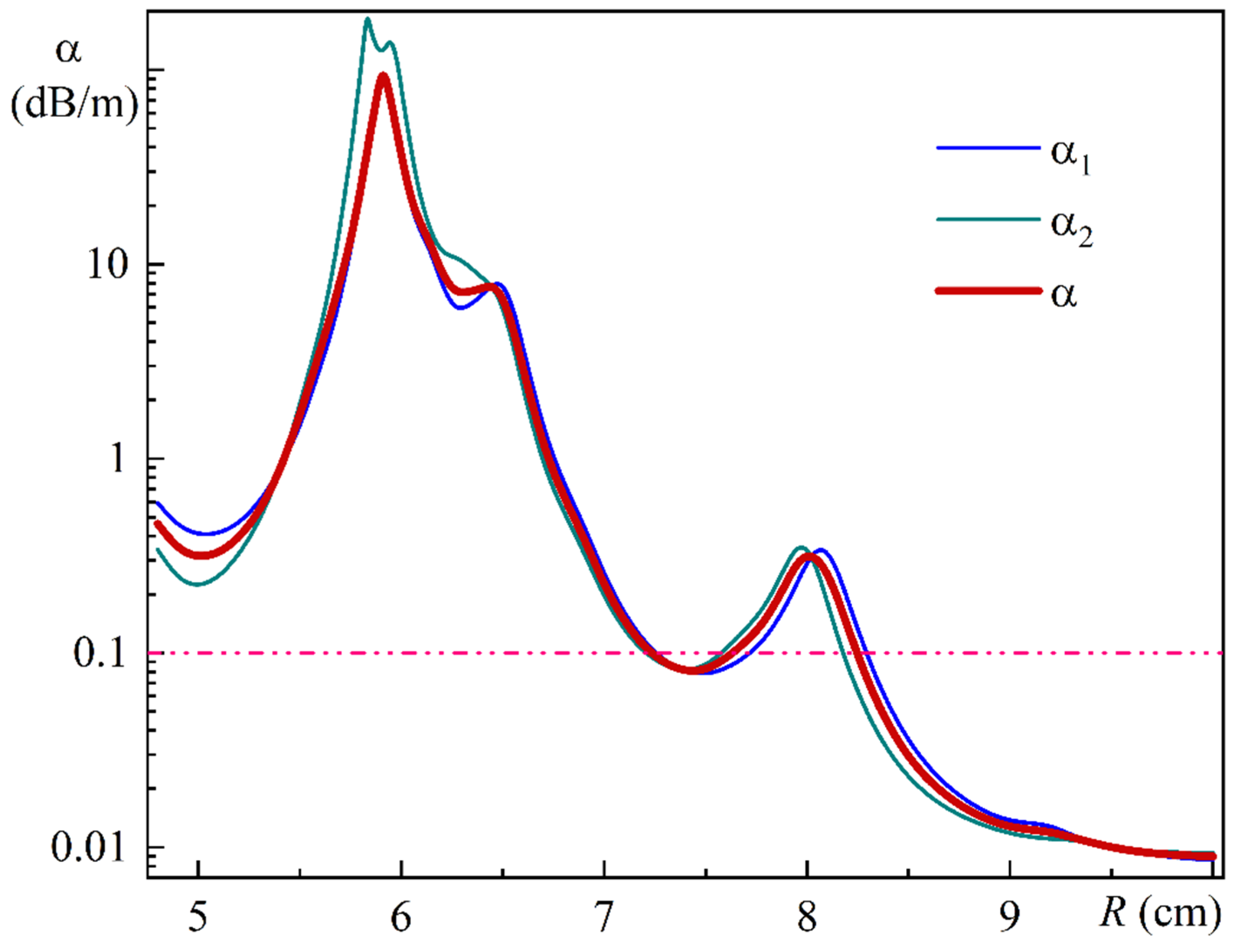
Figure 15 illustrates the MOF-18 leakage losses dependence on bending radius for radiation polarized along the
x-axis (α
1), along the
y-axis (α
2), and for unpolarized radiation (α).
As illustrated in
Figure 15, at a bending radius of 10 cm, the leakage loss of the MOF-18 with a polymer coating is approximately four times less than that of the uncoated MOF-18 [
21].
