Article

An Analysis and Optimization of Distortion Effect Caused by Pupil Decentering in Optical Gun Scope

Kunming Institute of Physics, Kunming 650223, China
*
Author to whom correspondence should be addressed.
Photonics 2024, 11(11), 995; https://doi.org/10.3390/photonics11110995
Submission received: 10 August 2024 / Revised: 1 October 2024 / Accepted: 7 October 2024 / Published: 22 October 2024
(This article belongs to the Special Issue Emerging Topics in Freeform Optics)

Abstract

:
During the use of optical gun scopes, slight movements between the human eye and the instrument can cause the pupil to offset from the optical axis, resulting in a dynamic distortion effect. This affects the accuracy and stability of aiming. Based on the mechanism, this study established parameters of the centroid’s deviation of image spots for marginal field points under pupil decentering and centering conditions and their differences to quantitatively evaluate the distortion. These evaluation parameters were obtained by performing a double integral calculation of the ray aberration distribution function over the entire designed exit pupil. Based on this evaluation method, three optical design strategies for reducing the distortion were proposed: optimizing ray aberrations, optimizing centroid shift of image spots, and utilizing vignetting effects. An optimization process was established by combining increasing vignetting and suppressing centroid shift. For a gun scope with significant distortion, the distortion effect was significantly weakened by increasing the vignetting factor and optimizing the centroid shift of image spots. This proved the effectiveness of the proposed analysis, evaluation, and optimization design methods.

1. Introduction

Optical gun scopes are representative of aiming telescopic systems without photoelectronic imaging devices, designed to provide a clear field of view and enhance accuracy when targeting. In military applications, the increasing demands of modern battlefields place heightened importance on the precision and reliability of these devices, directly influencing the combat effectiveness of personnel. High-quality optical gun scopes not only deliver clear imaging but also significantly enhance the tactical advantage of the shooter. In the civilian sector, optical gun scopes find widespread use in hunting, shooting sports, and personal defense. Modern civilian gun scopes are required to be lightweight, easy to operate, and capable of maintaining high accuracy over prolonged use. Consequently, achieving high performance while ensuring cost-effectiveness and the feasibility of mass production has become a key challenge within the optical manufacturing industry [1].
Optical gun scopes typically employ a continuous zoom telescope system, with the minimum magnification 1× commonly, which is critical for close-range targeting. To meet practical usage requirements, the exit pupil diameter of the optical gun scope (approximately 8 mm) must exceed the pupil diameter of the human eye (approximately 3–5 mm). This ensures that the viewer can observe the scene from various positions within a certain range on the exit pupil plane. During the aiming process, when the magnification is set to 1×, there is inevitably a slight shaking between the human eye and the instrument. This causes the pupil to oscillate laterally back and forth on the exit pupil plane. If the pupil is decentered from the optical axis of the gun scope, the observed scene will be distorted to some extent compared to the view when the pupil is centered [2,3]. The magnitude and direction of this distortion also vary with the shaking. Therefore, the observer perceives the scene through the gun scope as a twisting motion, causing dizziness [4]. This significantly hinders the accuracy of aiming [5,6].
In the literature on distortion analysis and correction, almost all focus on static distortion in the conventional sense, which is a basic aberration of imaging optical systems. Optical designers typically correct this distortion by controlling the deviation between the real image height of the chief ray and the ideal image height [7,8,9], ensuring that it meets the needs of the applications. These conventional methods for analyzing and correcting distortion have become well-established. For most optical gun scopes currently available on the market, distortion aberration is controlled within a small range in the design stage. However, during the actual use of the system, particularly at 1× magnification, the distortion effect caused by decentering of the pupil becomes significantly noticeable. This indicates that the conventional static distortion aberration is different with this dynamic distortion. Designers have yet to fully explore the mechanisms underlying this type of pupil-decentering-induced distortion in optical systems, and current literature offers little in terms of analyses or solutions. This has been a persistent challenge for many high-end optical gun scope manufacturers and designers for years. Therefore, it is necessary to correctly analyze the mechanism behind the pupil-decentering-induced distortion effect, establish effective evaluation parameters, and employ appropriate methods to suppress it, thus reducing the impact of shaking on aiming accuracy.

2. Analysis of Pupil-Decentering-Induced Distortion

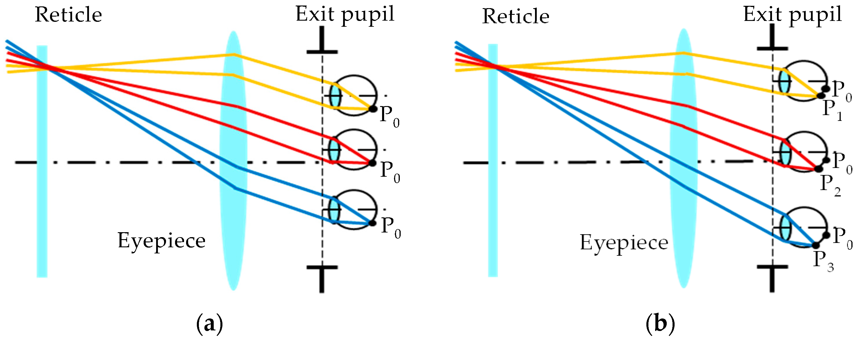
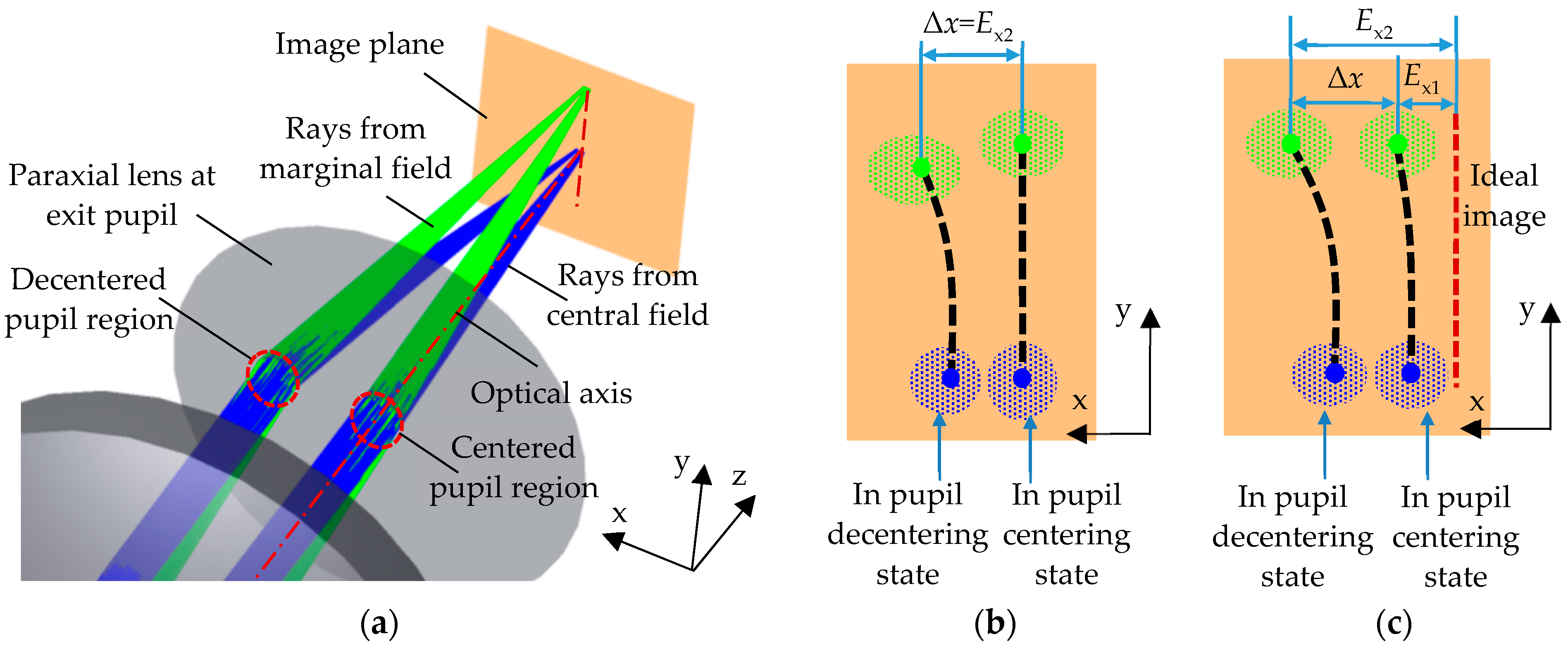
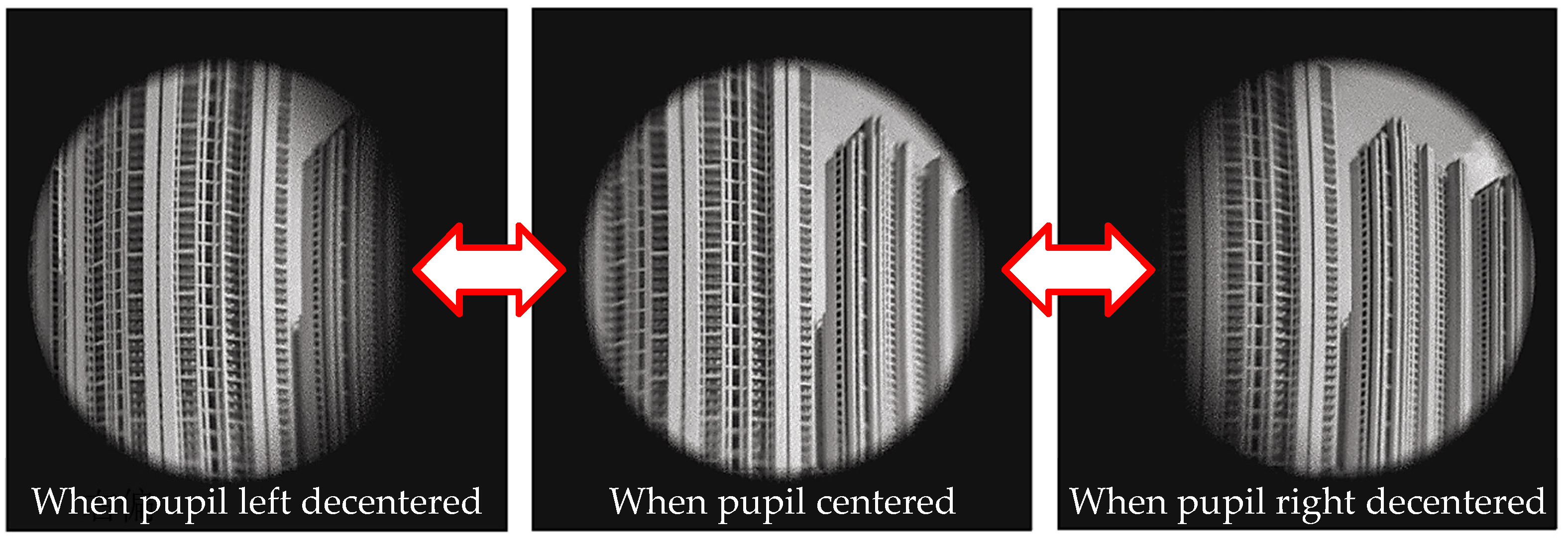
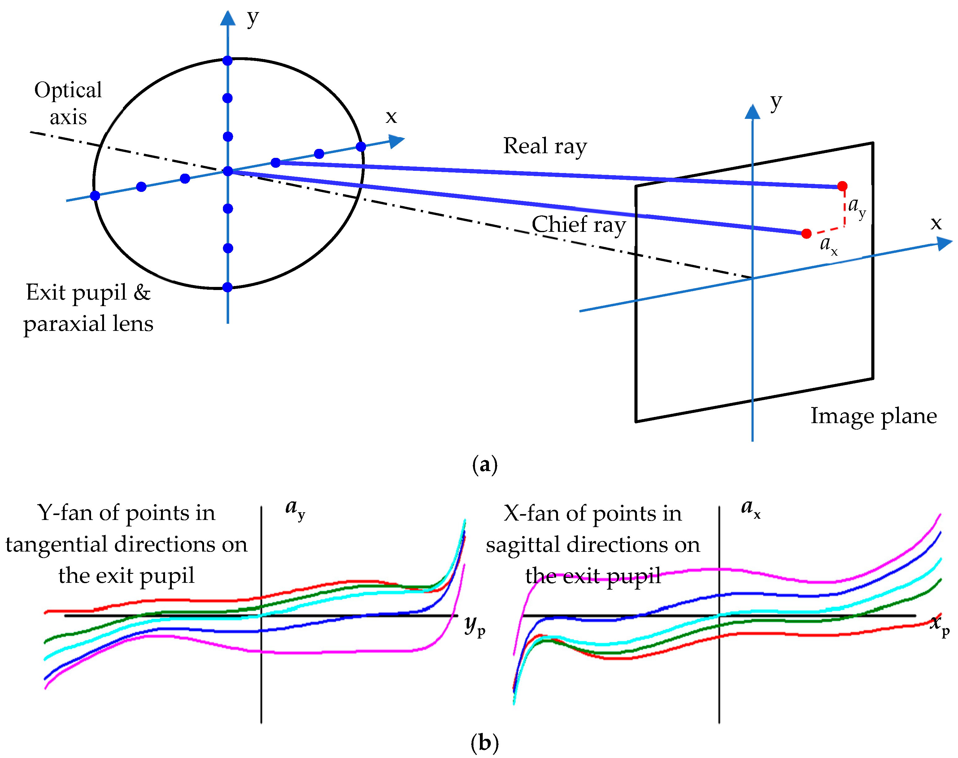
2.1. Mechanism Analysis

Optical gun scopes are typically composed of an objective lens, reticle, and eyepiece [10,11]. In an ideal condition, the exit light rays from the eyepiece are strictly parallel, thus the observed angles of exit light rays for the same object point are consistent when the pupil is at different positions, as shown in Figure 1a. However, real optical systems inevitably exhibit aberrations, and the light rays cannot be perfectly parallel. Consequently, when observing the same object point at different positions, the angles are inconsistent, as shown in Figure 1b. For gun scopes commonly with long eye relief, it is challenging to ensure that the human eye is always positioned precisely on the theoretically designed exit pupil plane during actual aiming. There is typically some axial movement within a certain distance range (approximately ±50 mm), which can increase optical aberrations [12]. If the human eye observes the scene at a different plane from the designed exit pupil plane, the deviation of the angles of the observed light rays becomes even larger. To make the analysis more relevant to practical usage, the term “exit pupil” used in this context refers to the actual plane where the human eyes’ pupil is positioned rather than the theoretically designed exit pupil plane.
If the human eye is considered an ideal optical system, the crystalline lens can be a paraxial lens, and its center corresponds to the optical axis. The pupil, acting as an aperture, is coplanar with the paraxial lens, and the retina serves as the image plane, as shown in Figure 1 [13,14,15]. During shaking, the axis of the human eye undergoes a lateral offset with respect to the axis of the gun scope. Due to the different angles of the light rays received, the deviation of the object point’s imaging position on the retina occurs with respect to the shaking human eye, deviating from P0 in Figure 1b to P1, P2, or P3. According to the features of a paraxial lens, the lateral offset only causes an overall shift in the image without changing its shape or size. Therefore, regardless of the position of the center of the paraxial lens, the relative deviation between the image points P1, P2, and P3 formed by the exit light rays and the ideal image point P0 remains unchanged. Thus, in optical design software such as Zemax 2017 or Code V 11.2, it is only necessary to use a large-aperture paraxial lens that fills the exit pupil to simulate a small-aperture crystalline lens at all positions. By selecting different sampling regions on the exit pupil plane to simulate pupil decentering, the shift of image spots on the retina can be calculated, as shown in Figure 2.
During the use of gun scopes, although the direction of movement between the human eye and the instrument is random, the rotational symmetry of the scope system allows for a simplified analysis. This study focuses on a simplified model where the pupil offsets along the x-axis, which is sufficient to represent the majority of random pupil decentering scenarios. Figure 2 illustrates the formed images after the light rays from two object points located on a vertical line in the object space of the gun scope, corresponding to the central field and the marginal field passing through the gun scope and converging by the paraxial lens. In the figure, the lower light rays and corresponding image spots originate from object points in the central field, while the upper from object points in the marginal field. In Figure 2a, the light rays pass through two circular regions of the pupil at different positions and are then focused by the paraxial lens onto the image plane. One pupil region is coaxial with the gun scope, while the other has an x-directional offset relative to the axis of the gun scope. As depicted in this Figure, the light rays emitted from each object point pass through the respective pupil regions, resulting in two clusters of spread image spots on the image plane, each with a centroid, as shown in Figure 2b,c. Figure 2b displays an image formed by a vertical line in the tangential plane, while Figure 2c depicts an image formed by a vertical line in the non-tangential plane.
In Figure 2b, due to the symmetry of the gun scope, the centroid of the image spots formed by the light rays from object points in the tangential plane, passing through the coaxial pupil region, will be located on the vertical line at the center of the image plane. These centroids have no x-directional deviation from the ideal image point. However, when the light rays pass through the decentered pupil region, the aberrations cause the centroids of the image spots to deviate in the x-direction from the ideal image point. The deviations corresponding to the central field and the marginal field are generally different. As a result, the formed image of a vertical line appears slightly curved, exhibiting subtle distortion. Similarly, in Figure 2c, the images formed by other vertical lines in the non-tangential plane also exhibit similar distortion effects. The difference is that, due to the inherent distortion aberration of the gun scope itself, the centroids of the image spots formed by the light rays passing through the coaxial pupil also deviate from the ideal image point.
Summarizing the two conditions in Figure 2b,c, for the same object point with a centered pupil, the x-directional deviation of the centroid of the image spots from the ideal image point is denoted as Ex1, which also represents the inherent distortion aberration of the gun scope. With a decentered pupil, the x-directional deviation is denoted as Ex2. The difference between the two, denoted as Δx, which is as follows:
Δ x = E x 2 E x 1
Δx represents the amount of shift in the x-coordinate of the centroid of the image spots after and before pupil decentering, and its magnitude and direction are dependent on the magnitude and direction of the pupil’s decentering. As mentioned above, although the optical system of the human eye (including the crystalline lens, pupil, and retina) undergoes a lateral group offset, the relative position between the image spot and the ideal image point remains unchanged regardless of the offset. Therefore, the difference Δx calculated in a model with a shared paraxial lens can reflect the shift of the centroid of image spots on the retina after the lateral group offset of the human eye’s optical system.
With a decentered pupil, the distortion of the entire image is not prominent when viewed statically. However, as shaking is a dynamic process, Δx continuously changes with the position of the eye. As a result, the observed scene appears to be continuously twisting. Even a small value of Δx can be perceived by the human eye during dynamic changes. Moreover, the larger the value of Δx is, the more pronounced the distortion caused by pupil decentering will be. Figure 3 shows the simulated pupil-decentering-induced distortion by LightTools 9.0 (2 mm lateral oscillation in both directions).

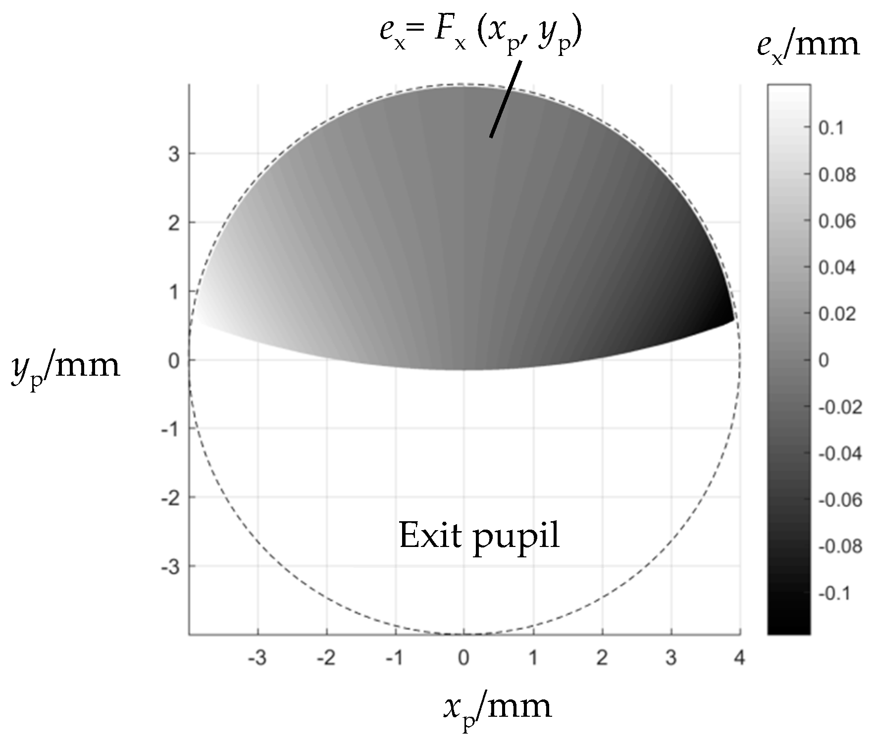
2.2. Distortion Evaluation

To reduce the dynamic distortion, it is necessary to define the parameters to evaluate its strength and then quantify them as an important indicator for the evaluation of gun scope design. These parameters will serve as important merit functions for automatic optimization.
From the analysis above, the strength of the distortion is reflected by Δx. In nature, it is caused by ray aberrations at different positions on the exit pupil. Therefore, the first step is to calculate the ray aberrations corresponding to different pupil regions on the exit pupil plane. For an object point within the field of view, any ray emitted from that point, and passing through the optical system composed of the gun scope and the human eye, forms an image spot on the image plane. The x-directional deviation value of ex between the formed image spot and the ideal image point is related to the ray’s coordinates (xp, yp) on the exit pupil plane. This can be expressed by the function Fx (xp, yp):
e x = F x x p , y p = x i f t a n θ x
xi represents the x-coordinate of the image spot, f′ is the combined focal length of the gun scope and the human eye, and θx is the field angle of the object point. Figure 4 depicts the distribution of ex for a specific object point on the tangential plane as a function of the exit pupil coordinates (xp, yp). In this figure, due to the vignetting, the effective region of Fx (xp, yp) does not fill the entire designed exit pupil.
After obtaining the distribution function Fx (xp, yp) for ex, it is possible to calculate the x-directional deviation of the centroid of image spots, denoted as Ex, through a double integral [16]:
E x = D F x x p , y p d x p d y p D d x p d y p
In the equation, D represents the effective integration region of the human eye’s pupil, as shown in Figure 5. Similarly, due to vignetting, the effective region of Fx (xp, yp) does not completely fill the entire human eye’s pupil in certain positions. By performing integration using Equation (3) for both the centered pupil region and the decentered pupil region, Ex1, Ex2 are obtained, respectively. Then, by using Equation (1) to calculate Δx, it can reflect the distortion in the x-direction when the pupil is decentered during the shaking process.
To accurately evaluate the distortion in practical use, it is necessary to select the decentering value of the pupil based on the actual usage as an evaluation input. For example, if the lateral oscillation for a gun scope is generally within the range of ±2 mm, the value of Δx can be calculated for evaluation by selecting the decentering value of −2 mm or 2 mm in the x-direction. Additionally, it is important to determine the field points being evaluated to ensure a comprehensive assessment of the distortion across the entire field of view. Typically, the distortion is larger at marginal fields. Accordingly, it is necessary to collect points with x-direction field values of negative, zero, and positive at the marginal fields, with one of these points reflecting the maximum distortion as much as possible. For the performance evaluation of optical systems, the normalized coordinates 0, ±0.707, ±1 are commonly used as the typical coordinates selected for evaluation. Since optical gun scopes usually have a circular field of view, the y coordinate appears as 0 when the x coordinate is ±1. Thus, it is difficult for the human eye to observe the distortion effect caused by pupil decentering in the x direction. Therefore, three field points with normalized coordinates of (−0.707, 0.707), (0, 1), and (0.707, 0.707) on the marginal field of view are chosen as specific field points for evaluation. The difference in deviation of the centroid in the pupil decentering and centering state is calculated as Δx, Δx0, Δx+, representing the distortion in the x-direction field values of negative, zero, and positive respectively, as shown in Figure 6.
In this process, the first step is to obtain three functions Fx (xp, yp) that represent the deviation values of image spots of object points in the three field positions shown in Figure 6; then select a maximum decentering value based on the actual usage and, under both pupil decentering and centering conditions, calculate the displacement Ex of the centroids of the three image spots from the ideal image points through integration; utilize Equation (1) to compute the corresponding values of Δx, Δx0, and Δx+. If any of these values are significant, it indicates that the distortion effect is visibly observable to the human eye. In such cases, the gun scope requires optimization and design improvements to reduce this effect.

3. Distortion Reduction

In the optical design of gun scopes, it is crucial to reduce the distortion caused by pupil decentering based on its mechanism and accurate evaluation. This study utilizes the analysis and automatic optimization features, along with macro programming, of optical design software such as Zemax or Code V, to propose three methods, discussing their respective advantages and disadvantages.

3.1. Optimization of Ray Aberration

The pupil-decentering-induced distortion is caused by ray aberration in the entire exit pupil of a gun scope. Ray aberration is the overall transverse aberration properties of an optical system. It can be obtained by real ray tracing and measured in image space with respect to the chief ray. Zemax and Code V provide analysis tools for ray aberrations [17,18]. In these software, ray aberrations, denoted as ax or ay, are distributed with the x-coordinate in the sagittal direction or the y coordinate in the meridian direction on the exit pupil plane. By tracing real rays from points in either the tangential or sagittal directions, as shown in Figure 7a, and subtracting the chief ray height from the real ray height in the x or y direction on the image plane, the corresponding ray aberrations can be listed, as shown in Figure 7b. These values of ray aberrations can then be utilized as the targets of merit functions for optimization.
Zemax also provides optimization operands such as TARX and TARY for ray aberrations, which enables automatic optimization of transverse aberration of rays with different field and pupil coordinates. Multiple configurations for optimization can be set to allow the exit pupil position to move a certain distance along the axis relative to the theoretical design position, thereby constraining the maximum absolute value of optical aberrations within a permissible range. This approach can mitigate the pupil-decentering-induced distortion of the gun scope. This offers readily available optimization operands, ease of implementation within the software, and significant improvement in image resolution for the gun scope.
However, this method imposes overly strict constraints on optimization, which hinders the overall optimization and balance of the optical system. While constraining ray aberration primarily enhances image resolution, it does not specifically target distortion reduction. However, in terms of human perception of ray aberration, its sensitivity to the dynamic distortion is much higher than it to image resolution. If ray aberrations are controlled to meet the requirements for the distortion as perceived by the human eye, the image resolution may far exceed human needs, leading to overdesign. If the gun scope itself is complex (e.g., continuous zoom gun scope with large zoom ranges), applying such overdesign may compromise the optimization of other aspects, such as tolerance, size, and cost, which may not meet the required needs.

3.2. Optimization of the Value of Δx

To control the distortion more effectively, parameters Δx, Δx0 and Δx+ can be used as the specific optimization merit functions. However, the integration calculation in Equation (3) is time-consuming and would lead to low efficiency. By converting the integration calculation to sampling, summation and averaging, the optimization process becomes more efficient [19].
To replace the double integration within the D region, the first is to sample within the pupil area. As the pupil is circular, a local polar coordinate system is established with the pupil center as the origin, and the polar coordinate variables θ and ρ are then sampled. If the number of samples for θ is M and the number of samples for ρ is N, the centroid deviation value Ex can be expressed as:
E x = m = 1 M n = 1 N F x ρ n c o s θ m , ρ n s i n θ m M e N e
m and n are the sampling indices for θ and ρ, respectively, while Me and Ne represent the effective number of samples for θ and ρ within the valid range of the D region. Equation (4) holds true if the principle of equal-area uniform sampling is satisfied, which means that the number of samples per unit area must be equal throughout the entire sampling range. Through derivation, it can be shown that if θ and ρ are sampled according to the rule given in Equation (5), this principle can be satisfied.
θ m = 2 π m Δ θ ρ n = n Δ ρ
Δθ and Δρ are the sampling intervals for θ and ρ respectively, equal to 1/M and 1/N respectively.
By applying the method described in Equation (4) to calculate the centroid deviation for each marginal field point, the Δx values can be obtained. These Δx values can then be incorporated into the macro program of optical design software as optimization operands, allowing for precise control and optimization of Δx, Δx0, and Δx+ values.

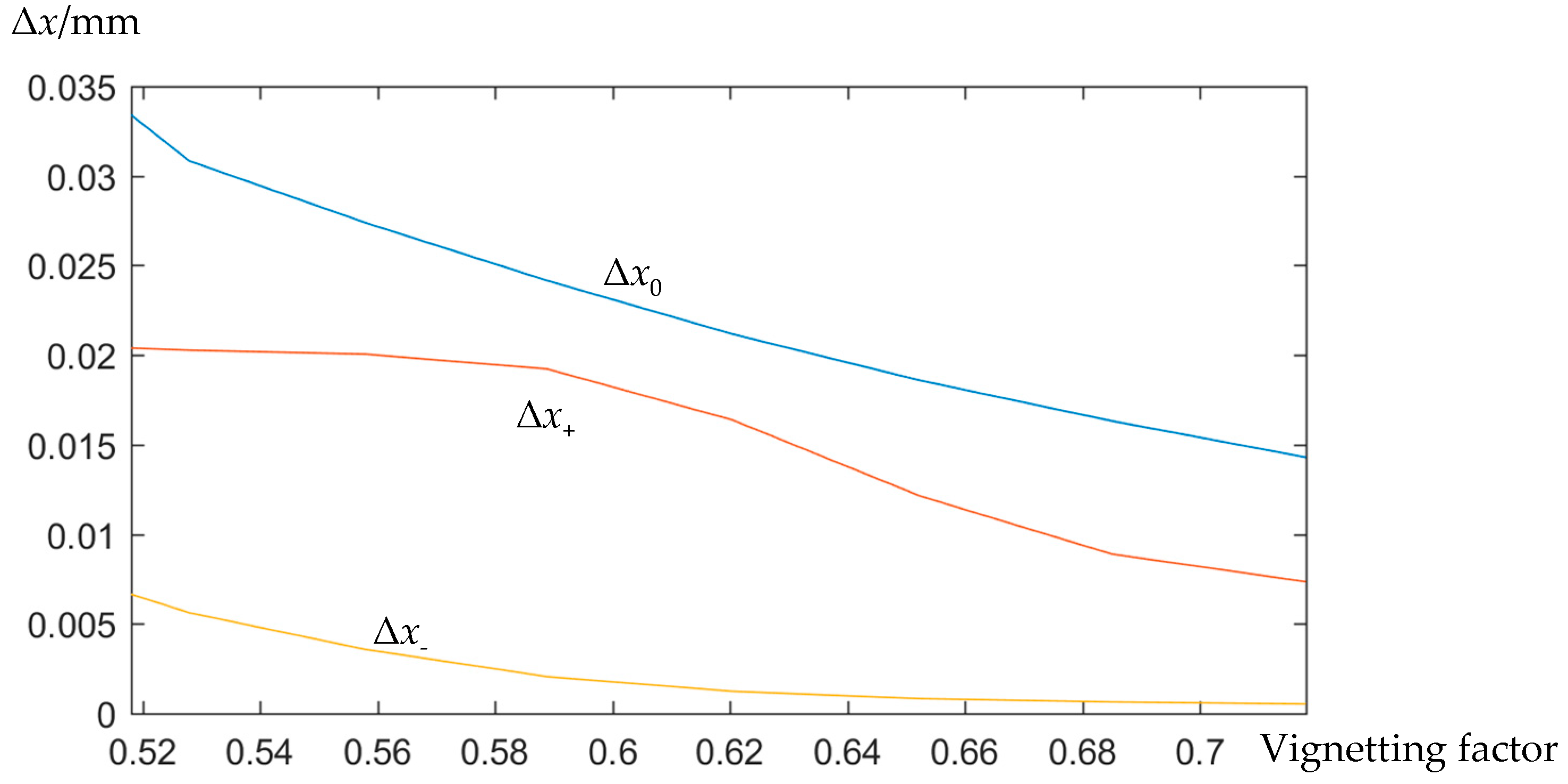
3.3. Utilization of Vignetting

According to Equation (3) and Figure 5, it can be inferred that Ex is closely related to the effective integration region D. Therefore, changing the region D can alter the value of Δx, and D is primarily influenced by vignetting. If Ex2 is significantly different from its corresponding pupil-centering centroid deviation Ex1, it is possible to introduce a small amount of vignetting by setting up a stop at an appropriate position or reducing the lens aperture, while ensuring that the image flux meets the visual requirements. By doing so, the effective integration region of Fx (xp, yp) for the marginal field point in the pupil decentering state is reduced, centralizing its centroid and decreasing the value of Δx [20]. Figure 8 shows the variation of the three Δx values with respect to the vignetting factor for an optical gun scope under a 2 mm pupil offset. For this scope, Δx0 and Δx+ are relatively large, both exceeding 0.01 mm, which could have a significant impact on practical applications. Overall, Δx, Δx0, and Δx+ all decrease as the vignetting factor increases.
The advantage of this method to control distortion is that it does not require drastic changes to the optical system. However, vignetting will lead to a certain amount of attenuation in the light energy of the marginal field, while design must ensure that the image energy meets certain requirements [21,22]. Therefore, the effectiveness of this method in reducing distortion is limited. In practical applications, it can be combined with methods that optimize the value of Δx to achieve better results.

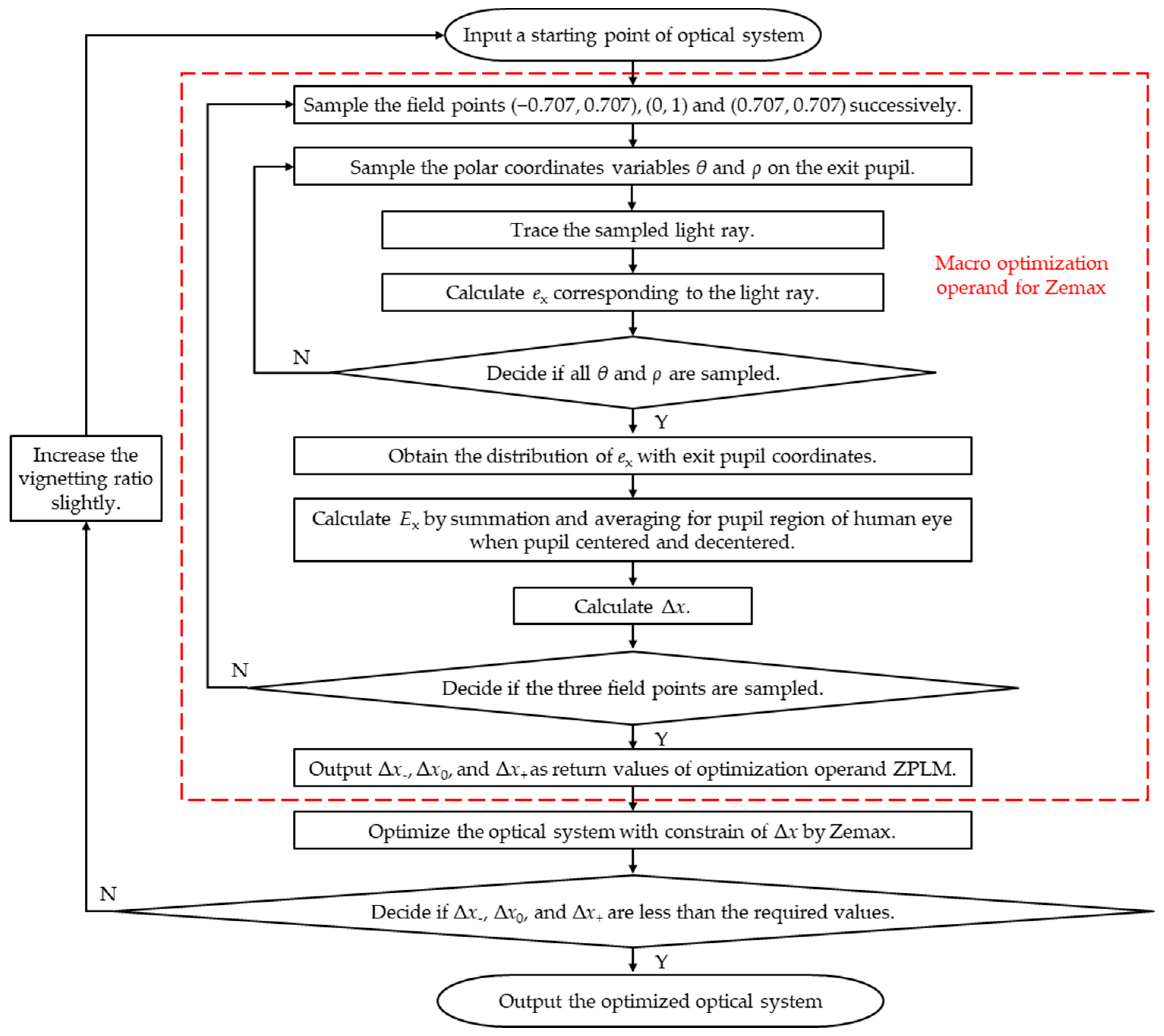
3.4. Basic Process for Optimizing the Distortion

Based on the advantages and disadvantages of the three methods discussed, we recommend a combined approach of increasing vignetting and suppressing Δx values. Based on Zemax, we establish a design process for optimizing the distortion effects for optical gun scopes, as illustrated in Figure 9. By utilizing the macro programming capabilities of Zemax, the calculation methods for Δx, Δx0, and Δx+, as described in Section 2 and Section 3.2, are implemented as ZPLM optimization operands. The sub-process within the dashed box in Figure 9 represents the programmed ZPLM optimization operands. These operands are optimized together with all other operands in merit functions of the optical system, including aberration, dimension, and tolerance constraints. During the optimization process, the vignetting coefficient is simultaneously adjusted to further reduce the Δx values.

4. Practical Application of Optimization Methods

In practical usage, a certain optical gun scope at 1× magnification exhibits a significant distortion effect caused by the movement of the human eye. Furthermore, as the distance between the eye and the designed exit pupil of the scope increases, the distortion becomes more pronounced, causing dizziness or discomfort for the observer. It is necessary to improve designs by analyzing and optimizing the distortion of the optical system in this gun scope to mitigate this effect.
The gun scope has an exit pupil diameter of 8 mm and an eye relief of 81 mm. During usage, the distance between the human eye and the designed exit pupil ranges from approximately −10 mm to 20 mm. The lateral movement of the eye have a range of approximately ±2 mm. Assuming a pupil diameter of 4 mm and a crystalline lens focal length of 17 mm, we establish an analysis and evaluation model under these conditions, and then calculate the distortion by the methods mentioned above.
Table 1 shows the centroid deviations of image spots in pupil decentering and centering state and their difference Δx for marginal field points with normalized field coordinates (−0.707, 0.707), (0, 1), and (0.707, 0.707) under the conditions of the eye being 20 mm away from the designed exit pupil and a decentered value of −2 mm. The results indicate that both Δx and Δx0 are relatively high. Figure 10 displays the simulation of the grid distortion caused by eye movement with LightTools. From this figure, it is evident that the distortion of the vertical lines in the grid is more pronounced in the pupil decentering state compared to the pupil centering state, particularly for the vertical lines at the central field. Figure 11 shows a photograph of the actual distortion effect caused by pupil decentering observed through the gun scope, which aligns with the simulation presented in Figure 10.
Improvements have been made to the optical system of the gun scope. Under the condition of meeting the required light flux, we reduce the aperture of a lens to increase the vignetting factor from 49% to 60% in the marginal field. Simultaneously, using Zemax software, a ZPLM macro operand was developed based on Equation (4) to calculate the centroid shifts. This was used to optimize and control the values of Δx, Δx0, and Δx+ for the gun scope, ensuring that their absolute values are less than 0.01 mm.
Table 2 presents the results after optimization, where the absolute values of Δx, Δx0, and Δx+ have all been controlled within 0.01 mm. Figure 12 displays the simulation results. The grid shows minimal changes between the decentered and centered states. After the gun scope is assembled, no distortion is observed when the eye moves, as shown in the actual photograph in Figure 13. Thus, it can be concluded that combining increased vignetting with optimized Δx effectively controls the distortion effect.

5. Conclusions

In response to the pupil-decentering-induced distortion caused by shaking in the use of optical gun scopes at 1× magnification, this study analyzes its mechanism from the perspective of ray aberrations. It proposes the parameter Δx, which reflects the strength of the distortion effect and is used to describe the shift of the centroid of image spots in pupil decentering states from centering states. By obtaining the ray aberration distribution function of image spots with respect to the exit pupil coordinates and performing a definite integral within the effective range of the human eye’s pupil region, the calculation of the Δx is realized. This study also proposes three methods for suppressing the distortion, namely optimizing ray aberrations, optimizing Δx, and utilizing vignetting. The focus is placed on optimizing the Δx values by establishing a fast computation through sampling, summation, and averaging, instead of integration. An optimizing process has been established by combining the methods of increasing vignetting and suppressing Δx values. In addition, improvement designs are carried out for an optical gun scope that exhibits significant distortion in practical use. By increasing the vignetting factor and utilizing the programmed macro-operands, Δx, Δx0, and Δx+ are optimized and controlled within an acceptable range. Comparative analyses of grid imaging simulations and reality imaging are conducted. The results confirm the effectiveness of the improvement design in suppressing distortion. This proves the correctness and practicality of the proposed analysis, evaluation, and optimization methods, providing an effective means to reduce distortion and aiming interference caused by shaking in optical gun scopes. The simplified model used in this study primarily applies to rotationally symmetric optical gun scopes. For a minority of non-rotationally symmetric gun scopes, as well as those equipped with photoelectronic imaging devices (such as night vision or infrared gun scopes), the situation becomes more complex. Further refinement of the model is needed to expand its applicability to these cases.

Author Contributions

Conceptualization, K.Y. and N.J.; methodology, K.Y. and N.J.; software, K.Y.; validation, D.Y., M.X. and S.D.; formal analysis, K.Y., N.J. and D.Y.; investigation, D.Y. and S.D.; resources, M.X.; data curation, K.Y.; writing—original draft preparation, K.Y.; writing—review and editing, D.Y. and M.X. All authors have read and agreed to the published version of the manuscript.

Funding

This research received no external funding.

Institutional Review Board Statement

Not applicable.

Informed Consent Statement

Not applicable.

Data Availability Statement

Data underlying the results presented in this paper are not publicly available at this time but may be obtained from the authors upon reasonable request.

Conflicts of Interest

The authors declare no conflicts of interest.

Nomenclature

fCombined focal length of the gun scope and the human eye
xiX-coordinate of the image spot
θxField angle of the object point
axX-directional transverse aberration with respect to the chief ray
ayY-directional transverse aberration with respect to the chief ray
exX-directional deviation between a real image spot and the ideal image point
xpRay’s x-coordinate on the exit pupil plane
ypRay’s y-coordinate on the exit pupil plane
Fx(xp, yp)Function expression for the distribution of ex with xp and yp
DEffective integration region of the human eye’s pupil for Fx (xp, yp)
ExX-directional deviation of the centroid of image spots
Ex1Ex in pupil centering state
Ex2Ex in pupil decentering state
ΔxShift in the x-coordinate of the centroid of the image spots after and before pupil decentering
ΔxΔx corresponding to an objebt point with normalized field coordinate of (−0.707, 0.707)
Δx0Δx corresponding to an objebt point with normalized field coordinate of (0, 1)
Δx+Δx corresponding to an objebt point with normalized field coordinate of (0.707, 0.707)
θLocal angular coordinate of the sampled point on the exit pupil
ρLocal radial coordinate of the sampled point on the exit pupil
MNumber of samples for θ
NNumber of samples for ρ
MeEffective number of samples for θ
NeEffective number of samples forρ
mSampling sequence number of θ
nSampling sequence number of ρ
θmThe m’th θ
ρnThe n’th ρ
ΔθSampling intervals for θ
ΔρSampling intervals for ρ

References

  1. Miks, A.; Novák, J. Method of paraxial design of rifle scope with four-element image-erecting zoom system and high zoom factor. Appl. Opt. 2019, 58, 4787–4796. [Google Scholar] [CrossRef] [PubMed]
  2. Jia, J.; Chan, T.T.; Lian, T.; Rio, K. Local pupil swim in Virtual- and Augmented-Reality: Root cause and perception model. J. Soc. Inf. Disp. 2023, 31, 1021–1040. [Google Scholar] [CrossRef]
  3. Chi, J.; Liu, J.; Wang, F.; Chi, Y.; Hou, Z. 3-D Gaze-Estimation Method Using a Multi-Camera-Multi-Light-Source System. IEEE Trans. Instrum. Meas. 2020, 69, 9695–9708. [Google Scholar] [CrossRef]
  4. Kaufeld, M.; Mundt, M.; Forst, S.; Hecht, H. Optical see-through augmented reality can induce severe motion sickness. Displays 2022, 74, 102283. [Google Scholar] [CrossRef]
  5. Fischler, M.; Campbell, D.; Atac, R.; Melzer, J. Application of large head-box aircraft transparency distortion measurement and compensation for improved cueing in helmet-mounted displays. Opt. Eng. 2017, 56, 051403. [Google Scholar] [CrossRef]
  6. Jiang, W.; Li, G.; Ren, G.; Li, D. Influence of vibration on stabilization performance of vehicle-mounted sighting telescope. Appl. Mech. Mater. 2014, 687–691, 3836–3839. [Google Scholar] [CrossRef]
  7. Allain, G.; Thibault, S. Lens design distortion management using orthogonal polynomial functions. Opt. Eng. 2023, 62, 035108. [Google Scholar] [CrossRef]
  8. Siew, R. Relative illumination and image distortion. Opt. Eng. 2017, 56, 049701. [Google Scholar] [CrossRef]
  9. Thibault, S.; Parent, J.; Zhang, H.; Larivière-Bastien, M.; Poulin-Girard, A.; Arfaoui, A.; Desaulniers, P. Developments in modern panoramic lenses: Lens design, controlled distortion, and characterization. In Proceedings of the International Conference on Optical Instruments and Technology (OIT2011), Beijing, China, 6–9 November 2011. [Google Scholar]
  10. Flynn, R.A.; Beadie, G. Using GRIN to save 50% lens weight for an 8x rifle scope design. In Proceedings of the Advanced Optics for Defense Applications: UV through LWIR II, 101810A, Anaheim, CA, USA, 9–13 April 2017. [Google Scholar]
  11. Siew, R. Concept, design, and manufacture of a 3X rifle gun sight. Proc. SPIE 2004, 5249, 281–287. [Google Scholar]
  12. Vrbik, J. Geometrical optics from the ground up. Appl. Math. 2020, 11, 1021–1040. [Google Scholar] [CrossRef]
  13. Zhao, Y.; Fang, F. Dynamic opto-mechanical eye model with peripheral refractions. Opt. Express 2023, 31, 12097–12113. [Google Scholar] [CrossRef] [PubMed]
  14. Petelczyc, K.; Bara, S.; Lopez, A.; Jaroszewicz, Z.; Kakarenko, K.; Kolodziejczyk, A.; Sypek, M. Imaging properties of the light sword optical element used as a contact lens in a presbyopic eye model. Opt. Express 2011, 19, 25602–25616. [Google Scholar] [CrossRef] [PubMed]
  15. Bakaraju, R.; Ehrmann, K.; Falk, D.; Ho, A.; Papas, E. Physical human model eye and methods of its use to analyse optical performance of soft contact lenses. Opt. Express 2010, 18, 16868–16882. [Google Scholar] [CrossRef] [PubMed]
  16. Strojnik, M.; Bravo-Medina, B.; Martin, R.; Wang, Y. Ensquared energy and optical centroid efficiency in optical sensors: Part 1, Theory. Photonics 2023, 10, 254. [Google Scholar] [CrossRef]
  17. Synopsys. CODE V Optimization Reference Manual; Synopsys: Pasadena, CA, USA, 2017. [Google Scholar]
  18. Ansys Company. User Manual of Ansys Zemax OpticStudio; Ansys Company: Canonsburg, PA, USA, 2022. [Google Scholar]
  19. Forbes, G.; Ruoff, J. Rapid evaluation of vignetting-free high-performance systems. Opt. Eng. 2018, 57, 101709. [Google Scholar] [CrossRef]
  20. Duplov, R. Angle-dependent vignetting stop. Opt. Eng. 2022, 61, 065106. [Google Scholar] [CrossRef]
  21. Zhang, D.; Yang, Q.; Chen, T. Vignetting correction for a single star-sky observation image. Appl. Opt. 2019, 58, 4337–4344. [Google Scholar] [CrossRef] [PubMed]
  22. Rosete-Aguilar, M.; Rayces, J. Eye rotation and vignetting in visual instruments. Appl. Opt. 2002, 41, 6593–6602. [Google Scholar] [CrossRef] [PubMed]
Figure 1. Angle and imaging position of rays from gun scope observed at different positions on the exit pupil plane. (a) Ideal optical system; (b) Real optical system.
Photonics 11 00995 g001
Figure 2. The imaging situation of the rays emitted by object points on vertical line of gun scope passing through centered and decentered pupil regions, respectively. (a) Schematic diagram of ray tracing; (b) Imaging of vertical line on a meridian plane; (c) Imaging of vertical line on a non-meridian plane.
Photonics 11 00995 g002
Figure 3. Simulated observation of scene twisting when the pupil shakes horizontally at the exit pupil plane of a gun scope.
Photonics 11 00995 g003
Figure 4. The distribution of ex from an object point of a gun scope.
Photonics 11 00995 g004
Figure 5. The distribution of ex in the effective integration region.
Photonics 11 00995 g005
Figure 6. Hand-drawn marginal field points with negative, zero, and positive x-coordinates and their Δx values.
Photonics 11 00995 g006
Figure 7. Ray aberration provided by optical design software (a) Diagram of ray tracing to calculate ray aberration (b) Plot of ray aberration curves.
Photonics 11 00995 g007
Figure 8. Relationships between Δx and vignetting factor.
Photonics 11 00995 g008
Figure 9. Flow chart for optimizing the distortion effect based on Zemax 2017.
Photonics 11 00995 g009
Figure 10. The grid of distortion caused by pupil decentering during the shaking for a gun scope simulated by LightTools.
Photonics 11 00995 g010
Figure 11. Photograph of the actual distortion effect observed through the gun scope.
Photonics 11 00995 g011
Figure 12. The grid of distortion caused by pupil decentering during the shaking for improved gun scope simulated by LightTools.
Photonics 11 00995 g012
Figure 13. Photograph of the actual distortion effect observed through the improved gun scope.
Photonics 11 00995 g013
Table 1. The deviations and their differences in the centroid of the image spots for a gun scope (in mm).
Normalized FieldEx2 (When Pupil Decentered)Ex1 (When Pupil Centered)Δx
(−0.707, 0.707)0.080060.10045Δx = −0.02039
(0, 1)−0.033420.00000Δx0 = −0.03342
(0.707, 0.707)−0.10711−0.10045Δx+ = −0.00666
Table 2. The deviations and their differences in the centroid of the image spots for improved gun scope (in mm).
Normalized FieldEx2 (When Pupil Decentered)Ex1 (When Pupil Centered)Δx
(−0.707, 0.707)0.052790.04613Δx = 0.00666
(0, 1)−0.009170.00000Δx0 = −0.00917
(0.707, 0.707)−0.03687−0.04613Δx+ = 0.00926
Disclaimer/Publisher’s Note: The statements, opinions and data contained in all publications are solely those of the individual author(s) and contributor(s) and not of MDPI and/or the editor(s). MDPI and/or the editor(s) disclaim responsibility for any injury to people or property resulting from any ideas, methods, instructions or products referred to in the content.

