A Widely and Continuously Tunable Single-Mode Transmitter Based on a Hybrid Microcavity Laser

 , ,
, ,  and
and 
Abstract
1. Introduction
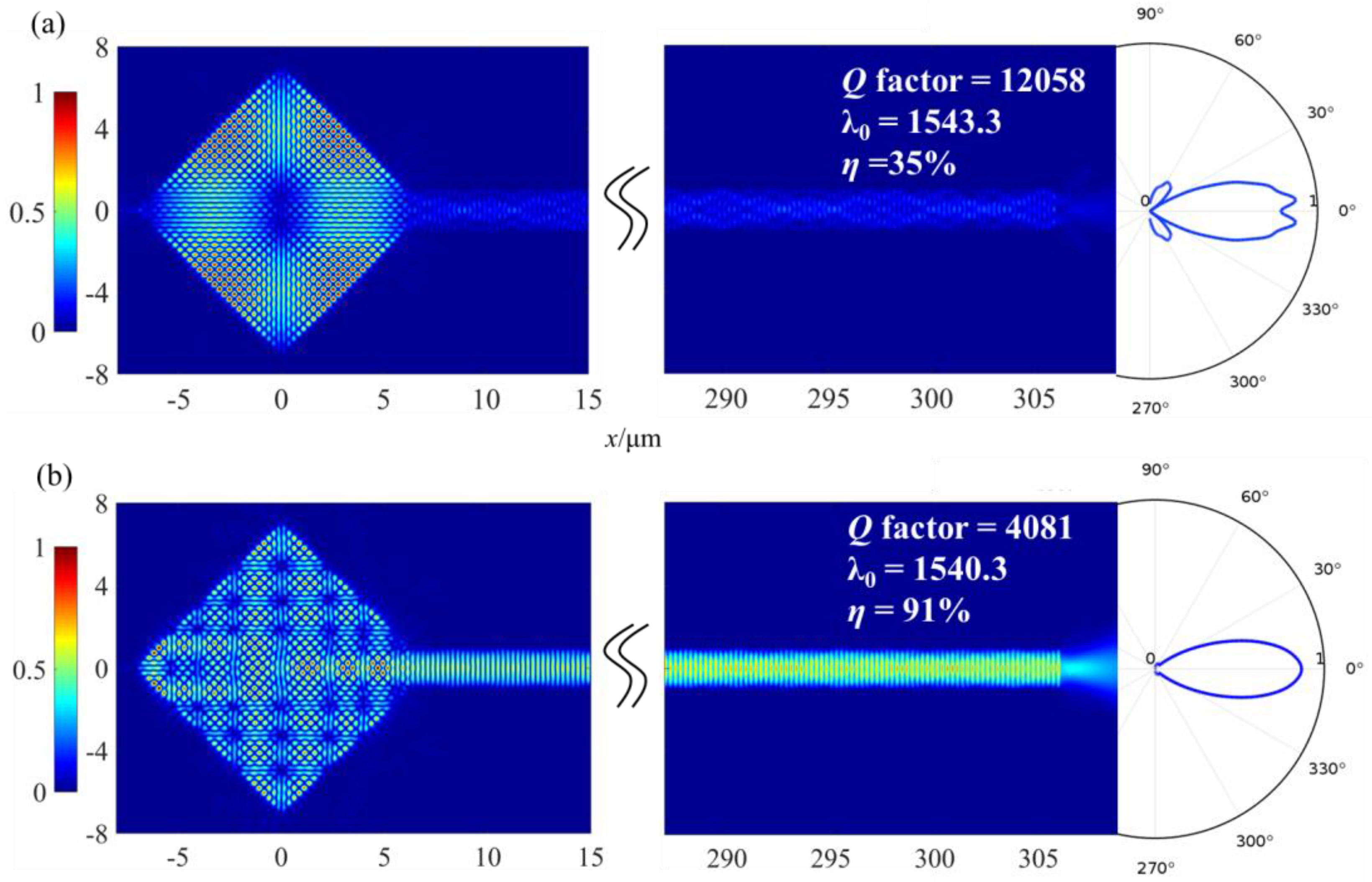
2. Square Microcavity
3. Hybrid Square-Rectangular Laser
4. Hybrid Square/Rhombus-Rectangular Laser
4.1. Theory
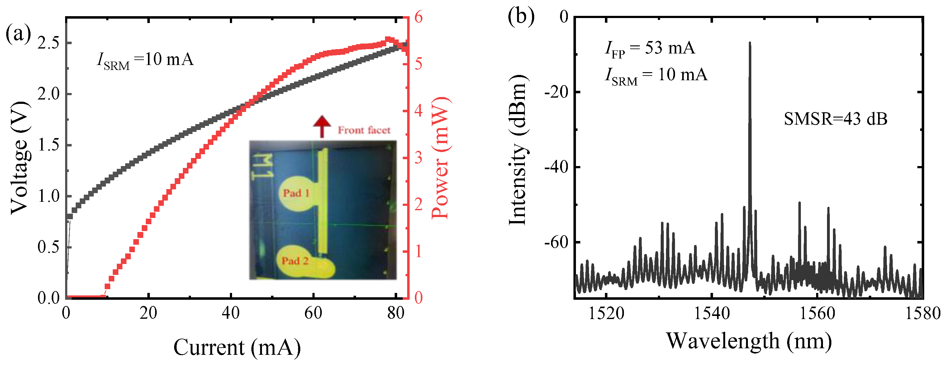
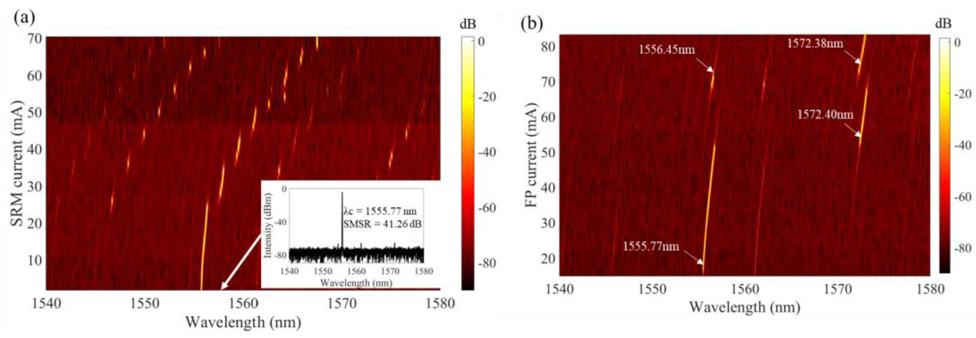
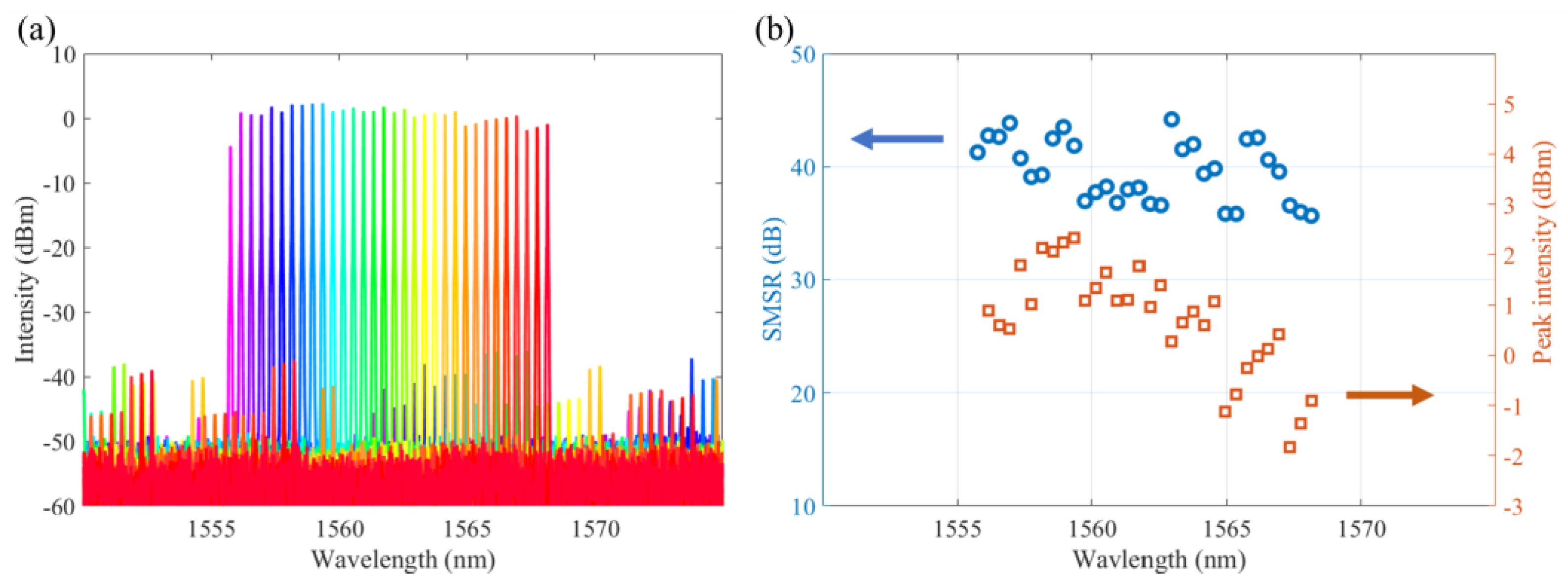
4.2. Experiment
5. Test Results After Packaging
6. Conclusions
Author Contributions
Funding
Institutional Review Board Statement
Informed Consent Statement
Data Availability Statement
Conflicts of Interest
References
- Wang, X.X.; Li, Z.X.; Wang, R.; Zhu, G.Y.; Qin, F.F.; Chen, J.P.; Wang, J.J.; Shi, Z.L.; Cui, Q.N.; Xu, C.X. Electrically driven optical resonance of spherical ZnO whispering gallery mode microcavity. Appl. Phys. Lett. 2021, 119, 021101. [Google Scholar] [CrossRef]
- Shi, L.L.; Wang, Q.Q.; Jiang, L.D.; Gao, Q.R.; Zhu, T. In-Fiber Butt-Coupled Spherical Microcavity with Whispering Gallery Mode and Fabry-Perot Resonances. IEEE Photonics Technol. Lett. 2021, 33, 553–556. [Google Scholar] [CrossRef]
- Drechsler, M.L.; Choi, L.S.M.; Tabataba-Vakili, F.; Nippert, F.; Koulas-Simos, A.; Lorke, M.; Reitzenstein, S.; Alloing, B.; Boucaud, P.; Wagner, M.R.; et al. Multimode Emission in GaN Microdisk Lasers. Laser Photon. Rev. 2024, 18, 2400221. [Google Scholar] [CrossRef]
- De Oliveira, R.; Colombano, M.; Malabat, F.; Morassi, M.; Lemaitre, A.; Favero, I. Whispering-Gallery Quantum-Well Exciton Polaritons in an Indium Gallium Arsenide Microdisk Cavity. Phys. Rev. Lett. 2024, 132, 126901. [Google Scholar] [CrossRef]
- Kryzhanovskaya, N.V.; Ivanov, K.A.; Fominykh, N.A.; Komarov, S.D.; Makhov, I.S.; Moiseev, E.I.; Guseva, J.A.; Kulagina, M.M.; Mintairov, S.A.; Kalyuzhnyy, N.A.; et al. III-V microdisk lasers coupled to planar waveguides. J. Appl. Phys. 2023, 134, 103101. [Google Scholar] [CrossRef]
- Mao, M.H.; Chien, H.C.; Hong, J.Z.; Cheng, C.Y. Room-temperature low-threshold current-injection InGaAs quantum-dot microdisk lasers with single-mode emission. Opt. Express 2011, 19, 14145–14151. [Google Scholar] [CrossRef]
- Mohideen, U.; Hobson, W.S.; Pearton, S.J.; Ren, F.; Slusher, R.E. GaAs/AlGaAs Microdisk Lasers. Appl. Phys. Lett. 1994, 64, 1911–1913. [Google Scholar] [CrossRef]
- Kryzhanovskaya, N.V.; Moiseev, E.I.; Nadtochiy, A.M.; Melnichenko, I.A.; Fominykh, N.A.; Ivanov, K.A.; Komarov, S.D.; Makhov, I.S.; Lutsenko, E.V.; Vainilovich, A.G.; et al. Output Power of III-V Injection Microdisk and Microring Lasers. IEEE J. Sel. Top. Quantum Electron. 2025, 31, 1501312. [Google Scholar] [CrossRef]
- Wang, J.W.; Li, X.; Guo, X.; Loh, T.; Ranno, L.; Liu, C.Y.; Rusli; Wang, H.; Sia, J.X.B. Scalable single-microring hybrid III-V/Si lasers for emerging narrow-linewidth applications. Opt. Express 2024, 32, 26751–26762. [Google Scholar] [CrossRef]
- Liang, D.; Fiorentino, M.; Okumura, T.; Chang, H.H.; Spencer, D.T.; Kuo, Y.H.; Fang, A.W.; Dai, D.; Beausoleil, R.G.; Bowers, J.E. Electrically-pumped compact hybrid silicon microring lasers for optical interconnects. Opt. Express 2009, 17, 20355–20364. [Google Scholar] [CrossRef]
- Yang, Y.D.; Huang, Y.Z. Mode characteristics and directional emission for square microcavity lasers. J. Phys. D-Appl. Phys. 2016, 49, 253001. [Google Scholar] [CrossRef]
- McCall, S.L.; Levi, A.F.J.; Slusher, R.E.; Pearton, S.J.; Logan, R.A. Whispering-Gallery Mode Microdisk Lasers. Appl. Phys. Lett. 1992, 60, 289–291. [Google Scholar] [CrossRef]
- Levi, A.F.J.; Slusher, R.E.; McCall, S.L.; Pearton, S.J.; Hobson, W.S. Room-Temperature Lasing Action In In0.51Ga0.49P/In0.2Ga0.8As Microcylinder Laser-Diodes. Appl. Phys. Lett. 1993, 62, 2021–2023. [Google Scholar] [CrossRef]
- Slusher, R.E.; Levi, A.F.J.; Mohideen, U.; McCall, S.L.; Pearton, S.J.; Logan, R.A. Threshold Characteristics of Semiconductor Microdisk Lasers. Appl. Phys. Lett. 1993, 63, 1310–1312. [Google Scholar] [CrossRef]
- Koch, S.W.; Jahnke, F.; Chow, W.W. Physics of Semiconductor Microcavity Lasers. Semicond. Sci. Technol. 1995, 10, 739–751. [Google Scholar] [CrossRef]
- Fujita, M.; Inoshita, K.; Baba, T. Room temperature continuous wave lasing characteristics of GaInAsP/InP microdisk injection laser. Electron. Lett. 1998, 34, 278–279. [Google Scholar] [CrossRef]
- Choi, S.J.; Djordjev, K.; Choi, S.J.; Dapkus, P.D. Microdisk lasers vertically coupled to output waveguides. IEEE Photonics Technol. Lett. 2003, 15, 1330–1332. [Google Scholar] [CrossRef]
- Kazes, M.; Lewis, D.Y.; Banin, U. Method for preparation of semiconductor quantum-rod lasers in a cylindrical microcavity. Adv. Funct. Mater. 2004, 14, 957–962. [Google Scholar] [CrossRef]
- Gies, C.; Wiersig, J.; Lorke, M.; Jahnke, F. Semiconductor model for quantum-dot-based microcavity lasers. Phys. Rev. A 2007, 75, 013803. [Google Scholar] [CrossRef]
- Tamboli, A.C.; Haberer, E.D.; Sharma, R.; Lee, K.H.; Nakamura, S.; Hu, E.L. Room-temperature continuous-wave lasing in GaN/InGaN microdisks. Nat. Photonics 2007, 1, 61–64. [Google Scholar] [CrossRef]
- Yan, C.L.; Wang, Q.J.; Diehl, L.; Hentschel, M.; Wiersig, J.; Yu, N.F.; Pflügl, C.; Capasso, F.; Belkin, M.A.; Edamura, T.; et al. Directional emission and universal far-field behavior from semiconductor lasers with limaccedilon-shaped microcavity. Appl. Phys. Lett. 2009, 94, 251101. [Google Scholar] [CrossRef]
- Jiang, X.F.; Xiao, Y.F.; Zou, C.L.; He, L.N.; Dong, C.H.; Li, B.B.; Li, Y.; Sun, F.W.; Yang, L.; Gong, Q.H. Highly Unidirectional Emission and Ultralow-Threshold Lasing from On-Chip Ultrahigh-Q Microcavities. Adv. Mater. 2012, 24, OP260–OP264. [Google Scholar] [CrossRef] [PubMed]
- Wang, D.Q.; Zhu, T.T.; Oliver, R.A.; Hu, E.L. Ultra-low-threshold InGaN/GaN quantum dot micro-ring lasers. Opt. Lett. 2018, 43, 799–802. [Google Scholar] [CrossRef] [PubMed]
- Yang, Y.D.; Wang, S.J.; Huang, Y.Z. Investigation of mode coupling in a microdisk resonator for realizing directional emission. Opt. Express 2009, 17, 23010–23015. [Google Scholar] [CrossRef]
- Song, Q.H.; Ge, L.; Stone, A.D.; Cao, H.; Wiersig, J.; Shim, J.B.; Unterhinninghofen, J.; Fang, W.; Solomon, G.S. Directional Laser Emission from a Wavelength-Scale Chaotic Microcavity. Phys. Rev. Lett. 2010, 105, 103902. [Google Scholar] [CrossRef]
- Wiersig, J.; Hentschel, M. Combining directional light output and ultralow loss in deformed microdisks. Phys. Rev. Lett. 2008, 100, 033901. [Google Scholar] [CrossRef]
- Chern, G.D.; Tureci, H.E.; Stone, A.D.; Chang, R.K.; Kneissl, M.; Johnson, N.M. Unidirectional lasing from InGaN multiple-quantum-well spiral-shaped micropillars. Appl. Phys. Lett. 2003, 83, 1710–1712. [Google Scholar] [CrossRef]
- Boriskina, S.V.; Benson, T.M.; Sewell, P.; Nosich, A.I. Q factor and emission pattern control of the WG modes in notched microdisk resonators. IEEE J. Sel. Top. Quantum Electron. 2006, 12, 52–58. [Google Scholar] [CrossRef]
- Tsang, W.T.; Olsson, N.A.; Logan, R.A. High-Speed Direct Single-Frequency Modulation with Large Tuning Rate and Frequency Excursion in Cleaved-Coupled-Cavity Semiconductor-Lasers. Appl. Phys. Lett. 1983, 42, 650–652. [Google Scholar] [CrossRef]
- He, J.J.; Liu, D. Wavelength switchable semiconductor laser using half-wave V-coupled cavities. Opt. Express 2008, 16, 3896–3911. [Google Scholar] [CrossRef]
- Gong, J.L.; Wang, Z.Y.; He, J.J.; Li, L.; Yang, R.Q.; Gupta, J.A. Single-mode interband cascade laser based on V-coupled cavity with 210 nm wavelength tuning range near 3 μm. Opt. Express 2023, 31, 38409–38418. [Google Scholar] [CrossRef] [PubMed]
- Liu, B.; Shakouri, A.; Bowers, J.E. Wide tunable double ring resonator coupled lasers. IEEE Photonics Technol. Lett. 2002, 14, 600–602. [Google Scholar] [CrossRef]
- Shang, L.; Liu, L.Y.; Xu, L. Single-frequency coupled asymmetric microcavity laser. Opt. Lett. 2008, 33, 1150–1152. [Google Scholar] [CrossRef]
- Phelan, R.; Guo, W.-H.; Lu, Q.; Byrne, D.; Roycroft, B.; Lambkin, P.; Corbett, B.; Smyth, F.; Barry, L.P.; Kelly, B.; et al. A novel two-section tunable discrete mode Fabry-Perot laser exhibiting nanosecond wavelength switching. IEEE J. Quantum Electron. 2008, 44, 331–337. [Google Scholar] [CrossRef]
- D’Agostino, D.; Lenstra, D.; Ambrosius, H.; Smit, M.K. Coupled cavity laser based on anti-resonant imaging via multimode interference. Opt. Lett. 2015, 40, 653–656. [Google Scholar] [CrossRef]
- Ma, X.W.; Huang, Y.Z.; Yang, Y.D.; Xiao, J.L.; Weng, H.Z.; Xiao, Z.X. Mode coupling in hybrid square-rectangular lasers for single mode operation. Appl. Phys. Lett. 2016, 109, 071102. [Google Scholar] [CrossRef]
- Xu, R.; Deng, C.S. New protection solution in native passive O-band CWDM for 5G front-haul. Telecom Eng. Tech. Stand. 2019, 32, 1–6. [Google Scholar] [CrossRef]
- Zhang, H.; Huang, W.P. Product Definition and Enabling Technologies for Product Definition and Enabling Technologies for 5G Wireless Transceiver. ZTE Technol. J. 2018, 24, 51–53. [Google Scholar] [CrossRef]
- Zhang, L.; Luo, Y.Q.; Ansari, N.; Gao, B.; Liu, X.; Effenberger, F. Enhancing Next Generation Passive Optical Network Stage 2 (NG-PON2) with Channel Bonding. In Proceedings of the 12th International Conference on Networking, Architecture, and Storage (NAS), Shenzhen, China, 7–9 August 2017; pp. 202–207. [Google Scholar]
- Hawthorn, C.J.; Weber, K.P.; Scholten, R.E. Littrow configuration tunable external cavity diode laser with fixed direction output beam. Rev. Sci. Instrum. 2001, 72, 4477–4479. [Google Scholar] [CrossRef]
- Ishii, H.; Kasaya, K.; Oohashi, H.; Shibata, Y.; Yasaka, H.; Okamoto, K. Widely wavelength-tunable DFB laser array integrated with funnel combiner. IEEE J. Sel. Top. Quantum Electron. 2007, 13, 1089–1094. [Google Scholar] [CrossRef]
- Ward, A.J.; Robbins, D.J.; Busico, G.; Barton, E.; Ponnampalam, L.; Duck, J.P.; Whitbread, N.D.; Williams, P.J.; Reid, D.C.J.; Carter, A.C.; et al. Widely tunable DS-DBR laser with monolithically integrated SOA: Design and performance. IEEE J. Sel. Top. Quantum Electron. 2005, 11, 149–156. [Google Scholar] [CrossRef]
- Caponio, N.P.; Goano, M.; Maio, I.; Meliga, M.; Bava, G.P.; Destefanis, G.; Montrosset, I. Analysis and Design Criteria of 3-Section DBR Tunable Lasers. IEEE J. Sel. Areas Commun. 1990, 8, 1203–1213. [Google Scholar] [CrossRef]
- Hao, Y.Z.; Wang, F.L.; Tang, M.; Weng, H.Z.; Yang, Y.D.; Xiao, J.L.; Huang, Y.Z. Widely tunable single-mode lasers based on a hybrid square/rhombus-rectangular microcavity. Photonics Res. 2019, 7, 543–548. [Google Scholar] [CrossRef]
- Wang, M.Q.; Hao, Y.Z.; Zhang, Z.N.; Zhang, B.; Yang, Y.D.; Xiao, J.L.; Teixeira, A.L.; Huang, Y.Z. Directly Modulated Tunable Single-Mode Lasers Based on a Coupled Microcavity. Photonics 2022, 9, 827. [Google Scholar] [CrossRef]
- Liu, J.C.; Huang, Y.Z.; Hao, Y.Z.; Fan, Y.R.; Wu, J.L.; Yang, K.; Xiao, J.L.; Yang, Y.D. Relative Intensity Noise and Linewidth for Hybrid-Cavity Semiconductor Lasers. J. Lightwave Technol. 2022, 40, 2087–2096. [Google Scholar] [CrossRef]
- Hao, Y.Z.; Sheng, M.W.; Zhang, Z.N.; Li, J.C.; Xiao, J.L.; Yang, Y.D.; Huang, Y.Z. High-Speed Directly Modulated Widely Tunable Hybrid Square/Rhombus-Rectangular Coupled Cavity Lasers. J. Lightwave Technol. 2023, 41, 5668–5674. [Google Scholar] [CrossRef]


Disclaimer/Publisher’s Note: The statements, opinions and data contained in all publications are solely those of the individual author(s) and contributor(s) and not of MDPI and/or the editor(s). MDPI and/or the editor(s) disclaim responsibility for any injury to people or property resulting from any ideas, methods, instructions or products referred to in the content. |
© 2024 by the authors. Licensee MDPI, Basel, Switzerland. This article is an open access article distributed under the terms and conditions of the Creative Commons Attribution (CC BY) license (https://creativecommons.org/licenses/by/4.0/).
Share and Cite
Wang, M.-Q.; Zhang, B.; Zhang, Z.-N.; Hao, Y.-Z.; Hu, Z.-H.; Yang, Y.-D.; Xiao, J.-L.; Teixeira, A.L.; Huang, Y.-Z. A Widely and Continuously Tunable Single-Mode Transmitter Based on a Hybrid Microcavity Laser. Photonics 2024, 11, 1080. https://doi.org/10.3390/photonics11111080
Wang M-Q, Zhang B, Zhang Z-N, Hao Y-Z, Hu Z-H, Yang Y-D, Xiao J-L, Teixeira AL, Huang Y-Z. A Widely and Continuously Tunable Single-Mode Transmitter Based on a Hybrid Microcavity Laser. Photonics. 2024; 11(11):1080. https://doi.org/10.3390/photonics11111080
Chicago/Turabian StyleWang, Miao-Qing, Bin Zhang, Zhen-Ning Zhang, You-Zeng Hao, Zun-Hao Hu, Yue-De Yang, Jin-Long Xiao, António L. Teixeira, and Yong-Zhen Huang. 2024. "A Widely and Continuously Tunable Single-Mode Transmitter Based on a Hybrid Microcavity Laser" Photonics 11, no. 11: 1080. https://doi.org/10.3390/photonics11111080
APA StyleWang, M.-Q., Zhang, B., Zhang, Z.-N., Hao, Y.-Z., Hu, Z.-H., Yang, Y.-D., Xiao, J.-L., Teixeira, A. L., & Huang, Y.-Z. (2024). A Widely and Continuously Tunable Single-Mode Transmitter Based on a Hybrid Microcavity Laser. Photonics, 11(11), 1080. https://doi.org/10.3390/photonics11111080