Article

Optical System Design of a Self-Calibrating Real Entrance Pupil Imaging Spectrometer

1
Anhui Institute of Optics and Fine Mechanics, Hefei Institutes of Physical Science, Chinese Academy of Sciences, Hefei 230031, China
2
Science Island Branch, Graduate School of USTC, Hefei 230026, China
3
Key Laboratory of Optical Calibration and Characterization, Chinese Academy of Sciences, Hefei 230031, China
*
Authors to whom correspondence should be addressed.
Photonics 2024, 11(11), 1072; https://doi.org/10.3390/photonics11111072
Submission received: 9 October 2024 / Revised: 31 October 2024 / Accepted: 10 November 2024 / Published: 15 November 2024

Abstract

:
Presently, on-orbit calibration methods have several problems, such as low calibration accuracy and broken traceability links, so an urgent need exists to unify traceable and high-precision on-orbit radiometric calibration loads as benchmarks for cross-transfer radiometric calibration. Considering the deficiencies of current on-orbit calibration, this paper proposes adjusting the size of the variable diaphragm at the entrance pupil and the integration time to attain large dynamic attenuation, converting the radiometric calibration into absolute geometric calibration of the attenuation device, and realizing a self-calibrating real entrance pupil imaging spectrometer (SCREPIS) that can be directly used to view the Earth and the Sun and quickly obtain apparent reflectance data. An initial structural design method based on the distance between individual mirrors is proposed according to the instrument design requirements. The design of a real entry pupil image-side telecentricity off-axis three-reflector front optical system with a 7° field of view along the slit direction, a 3.7 systematic F-number, and a 93 mm focal length is finally realized, and the system image plane energy is verified to change proportionally to the variable diaphragm area. Finally, the front system and rear Offner optical system are jointly simulated and optically designed. The system provides instrumental support for cross-calibration and theoretical support and a technical basis for planning space-based radiation references.

1. Introduction

During launch and on-orbit operation, remote sensing instruments are susceptible to mechanical vibration, environmental changes, and other factors, resulting in changes in their performance. Therefore, high-frequency radiation calibration is needed to monitor and track the on-orbit operation status of payloads, to promptly correct the data of payloads, and to ensure the accuracy of the observation data [1,2,3]. At present, three main on-orbit calibration methods are used for radiation remote sensing instruments: on-board calibration, on-orbit vicarious calibration, and on-orbit cross-calibration [4,5,6,7,8,9,10]. For payloads equipped with onboard calibrators (such as lampboard, solarboard, and transfer radiometers), the onboard calibration method is commonly used. After launch, onboard calibration relies entirely on the stability of the calibrator itself to ensure its expected accuracy, severing traceability to ground-based metrology laboratories [4,5]. Most payloads without onboard calibrators employ on-orbit vicarious calibration or on-orbit cross-calibration. Vicarious calibrations require simultaneous measurements with ground-based instruments, using ground measurements in atmospheric transmission models for inversion. This method is relatively common but time-consuming and labor-intensive. Cross-calibration generally involves high-precision reference payloads observing the same nadir point simultaneously with the payload to be calibrated, facilitating the transfer of measurement values. This method can enhance the on-orbit radiometric calibration accuracy and data consistency among different payloads [7,8,9].
Currently, cross-calibration typically employs high-precision apparent reflectance data for transfer [7,8,9]. Therefore, the uncertainty in the instrument’s measurement of apparent reflectance directly impacts the accuracy of on-orbit cross-calibration. The onboard calibrator has two main methods for measuring the Earth’s apparent reflectance: indirect and direct observation methods. The indirect observation method primarily uses third-party media to obtain the Earth’s apparent reflectance. For example, ATSR-2 employs a diffuse reflector [11], AVHRR3 uses uniform sites [12], and the MERSI sensor on FY-3 leverages standard detectors to calibrate the instrument’s radiance [13]. By converting the instrument’s Digital Number (DN) output of Earth’s observations, the apparent radiance is determined [4,5,6,7,8,9,10]. The Earth’s apparent reflectance can then be calculated using the solar irradiance measured by the diffuse reflector or derived from the solar constant [14]. The current calibration uncertainty of this method ranges from 3% to 5%. The main sources of error are limited by not only third-party media but also the inconsistency in error sources between radiance and irradiance values, leading to unbalanced error factors that affect the improvement of reflectance accuracy. Subsequent optimizations have been made on the basis of this method. MODIS considers the degradation factor of the standard reference plate and obtains the Earth’s apparent reflectance through the ratio of signals from the diffuse reflector and the Earth. This approach has improved the measurement uncertainty to 2%, making it the currently recognized payload with the highest calibration accuracy [14,15,16,17]. The direct observation method is currently under development with a Hysics instrument [16]. The basic principle is to attenuate solar brightness to the same order of magnitude as the Earth using an attenuation device, enabling the same instrument to measure the Earth’s radiance and solar irradiance in a short time, thus eliminating the influence of detector degradation. Moreover, this system can achieve performance monitoring by selecting variable diaphragm materials and conducting periodic lunar observations for the entire instrument. This method avoids errors caused by the attenuation of third-party media and can improve the calibration accuracy by an order of magnitude [15,16,17]. Consequently, various countries are competing to develop remote sensing payloads capable of obtaining high-precision apparent reflectance data to serve as benchmark space payloads for cross-calibration.
Based on the instrument’s application requirements, the entire optical system consists of a front-end imaging system and a back-end spectroscopic system [15,16,17]. The current design challenge lies in achieving a front-end imaging system with an entrance pupil, image-space telecentricity, a large field of view, and a low F-number. The entrance pupil indicates that the aperture stop is located at the front of the entire system, enabling the placement of a variable aperture at the pupil position. This allows the size of the variable diaphragm to be directly proportional to the optical flux entering the system, and subsequently, to the energy on the image plane. Thus, the radiometric calibration can be transformed into a calibration based on a linear geometric attenuation factor. The image-space telecentric design ensures pupil matching between the front-end imaging system and the back-end spectroscopic system. A low F-number improves the system’s signal-to-noise ratio, thereby enhancing calibration accuracy. The large field-of-view design employs an off-axis three-mirror optical system, which not only increases the observation swath but also meets the requirements for wide spectral bands [18,19,20,21]. The back-end spectroscopic system utilizes an Offner concentric configuration, which offers advantages such as low inherent aberration, minimal spectral line curvature and chromatic distortion, high imaging quality, and a compact structure, making it suitable as a dispersive system for high-resolution imaging spectrometers [16,17,18,19,20,21,22].
Therefore, the design of the optical system is highly demanding. The off-axis triple-mirror systems designed in the current literature mostly have an aperture stop located on the secondary mirror, which is a typical Cooke TMA system. Most of these systems have a more regular structure, and the requirements of a wide field of view and appropriate telecentricity can be easily realized. However, the Cooke TMA system has a virtual focal point, and the pupil is located behind the primary mirror. If the variable diaphragm must be placed in front of the entire system, then the image plane energy and the variable diaphragm area will not be proportional to each other, which is unsatisfactory for applications of imaging systems with real entry pupil requirements [23,24,25,26,27,28,29]. In a Rug TMA system, the aperture stop is located in front of the main mirror of the off-axis triple-mirror system, which can meet the real pupil requirements for imaging system applications. For example, when an optical window, a variable diaphragm, or a pointing mirror is in front of the imaging system, the real pupil of the system must have the same position and size as the window or mirror in front of the system to meet the imaging system field-of-view and energy requirements. However, designing an image-side telecentric optical path is more difficult for the Rug TMA system. In particular, because the SCREPIS requires a large field of view (generally greater than 5°), a small F-number (generally less than 5), a real pupil, image-side telecentricity, and easy processing and adjustment of the Rug TMA system itself, the design of the system poses difficulties, and few reports exist in the literature [30,31,32,33,34]. In this paper, we address the shortcomings of the current Rug TMA system for optical research and design.
The off-axis three-mirror optical system is obtained through aperture off-axis or field-of-view off-axis optimization on the basis of the coaxial three-mirror system. Therefore, a suitable starting point is crucial for successful optical design. The current references for the initial structure are based on the known values of the four profile parameters α1, α2, β1, and β2, which are substituted into the optical path imaging formula to solve for the structural parameters of the coaxial optical system [23,24,25,26,27,28,29,30,31,32,33]. Optical simulation software is used to design the initial structure of the coaxial system, and then, eccentricity and off-axis variables are added on the basis of the coaxial system for optimization to obtain an off-axis triple-mirror system with better image quality. However, this method requires multiple sets of shielding ratios and magnification combinations, and the selection of the value ranges of α1, α2, β1, and β2 by general optical designers is mostly based on empirical values [30]. (Here, α1 represents the obscuration ratio of the secondary mirror to the primary mirror, α2 indicates the obscuration ratio of the tertiary mirror to the secondary mirror, β1 denotes the magnification of the secondary mirror, and β2 signifies the magnification of the tertiary mirror.) In addition, this method is used for three-mirror systems with the aperture stop on the secondary mirror, and initial structure derivations of the center of the aperture for a small F-number, a large field of view and no higher-order aspheres and a software optimization design process have not been reported in detail.
In response to the above deficiencies, this paper proposes a method that applies to all cases (the aperture stop is located in front of the primary mirror, on the primary mirror, on the secondary mirror, at the primary imaging plane, and at the secondary imaging plane) and can be used for initial structural selection according to the required structural form of the designed off-axis three-mirror system and other requirements. For the coaxial three-mirror system, the distance between each mirror, namely, d1, d2, and d3, is intuitively clear and affects the structural layout and size of the final design of the entire system. To select d1, d2, and d3, values based on experience are unnecessary, and only each mirror interval needs to be reasonably allocated. Then, the structural parameters are substituted to deduce the formula used to obtain the initial structure of the system. In this work, the distance between the three coaxial mirrors is known, the initial structure is obtained through algorithm programming, and pre-optical design is conducted by controlling the relevant parameters of the optical path. Finally, a posterior Offner spectroscopic system is designed for the cosimulation design of the entire SCREPIS. The optical and mechanical design of the SCREPIS provides instrument support for cross-calibration and theoretical support and a technical basis for planning space-based radiation data [1,2,3].

2. Principles

2.1. Working Principle of the Instrument

The SCREPIS combines imaging technology and spectral technology to simultaneously obtain target images and their spectral characteristics. A slit is used to organically combine the front optical imaging system and the rear spectroscopic system, which are independently used. SCREPIS can be used not only to acquire high-resolution spatial images but also, via spectroscopy, to determine all the absorption or reflection spectral features of ground substances.
The basic principle of the SCREPIS is as follows: Since there is a five-order magnitude difference between the solar and Earth radiances, this paper adjusts the size of the variable diaphragm at the entrance pupil and the integration time of the detector to bring the two radiances to the same order of magnitude. The workflow of the instrument is shown in Figure 1a. First, a large-aperture variable diaphragm is placed at the entrance pupil to observe the ground target and measure its radiance, as shown in Equation (1). Second, a small-aperture variable diaphragm is switched in at the entrance pupil and the detector integration time is adjusted to integrate the solar disc, thereby obtaining the spectral irradiance of the Sun, as shown in Equation (2). The luminous flux into the system is proportional to the variable diaphragm area and thus proportional to the response signal of the image detector. Knowing the area scaling factor of variable diaphragms of different sizes, traditional radiometric calibration can be converted into absolute calibration of the variable diaphragm attenuation coefficient, with the attenuation factor shown in Equation (3). The ground reflectance at the current observation angle is calculated by comparing the two measurements, as shown in Equation (4).
L i , λ e a r t h = S i , λ e a r t h S i , λ d a r k R i , λ
E λ s o l a r = 1 δ λ x s o l a r y s o l a r S i , λ s o l a r S i , λ d a r k R i , λ
δ λ = A e a r t h A s o l a r × t e a r t h t s o l a r
ρ i , λ e a r t h = π L i , λ e a r t h E λ so l a r = π δ λ S i , λ e a r t h S i , λ d a r k R i , λ x s o l a r y s o l a r S i , λ s o l a r S i , λ d a r k R i , λ = π δ λ S i , λ e a r t h S i , λ d a r k x s o l a r y s o l a r S i , λ s o l a r S i , λ d a r k
where δ λ is the attenuation coefficient related to the variable diaphragm area and the integration time. The sum of x s o l a r and y s o l a r is used to integrate the output of a single detector across the entire solar disc needed to measure the solar irradiance. S i , λ s o l a r is the output signal of pixel i when observing the Sun; S i , λ d a r k is the dark signal. S i , λ e a r t h is the output signal of pixel i when observing the Earth. S i , λ d a r k is the dark signal. R i , λ is the calibration coefficient when observing the Sun. R i , λ is the calibration coefficient when observing the Earth. Because the observation times of the Sun and the Earth are very short and the luminous flux decays to the same order of magnitude, the calibration coefficients can be approximately the same. A e a r t h and A s o l a r are the areas of the variable stop when observing the Earth and Sun, respectively. t s o l a r and t e a r t h are the integral times used by the probe when observing the Sun and Earth, respectively.
The schematic diagram of the instrument composition and working principle is shown in Figure 1b. The variable aperture can be constructed using materials with a low coefficient of thermal expansion. Research indicates that the thermal expansion coefficient of the material used, specifically Invar Steel, ranges from 10 × 10−6 to 15 × 10−6 °C [35]. Given that the payload is equipped with a temperature control system, the on-orbit temperature variation does not exceed 20 °C. Using Invar Steel’s linear expansion coefficient, we can calculate that the length change caused by temperature variation is one in five thousand of the original length, resulting in an area change of one in two thousand five hundred of the corresponding aperture area. This change can be considered negligible in terms of its impact on the results. The electronics employ detectors with good linearity and utilize variable apertures with different attenuation factors to periodically observe the Moon. This approach allows for the verification of the detector’s linearity, enabling timely corrections and adjustments to ensure that the linearity remains consistent across two orders of magnitude during operation. Nevertheless, the influence of small aperture diffraction must be considered [36]. Therefore, the diameter of the aperture cannot be excessively minimized, resulting in the selection of a small aperture with a diameter of approximately 0.5 mm. Furthermore, due to the high precision requirements for the instrument’s reflectance calibration, the entire system requires a small F-number (f/D). Coupled with the demands for miniaturization and weight reduction of the instrument, a large aperture with a diameter of 25 mm is chosen. This design allows for a geometric area change that can attenuate the energy by three orders of magnitude. In addition, owing to the close proximity of the two observation times, the calculation results are unaffected by the long-term degradation of the instrument response. In this way, the entire instrument can be converted from traditional radiometric calibration to absolute geometric attenuation factor calibration. Owing to the high accuracy of geometric calibration, traceable and highly accurate reflectance measurements are achieved, and the reflectance values can be transferred to other remote sensing instruments that perform observations at the same time and in the same direction, thus cross-transferring the calibration.

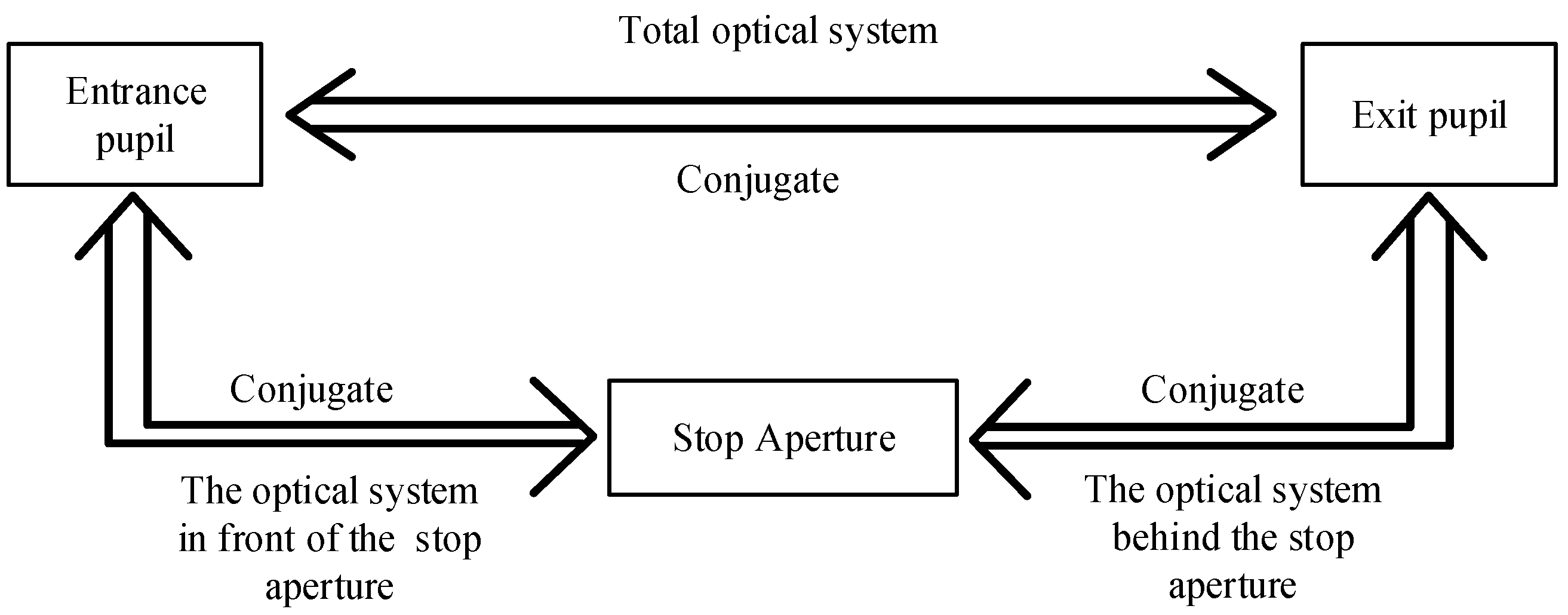
2.2. Principles of the Optical System Design

Theoretical analysis compares the Cooke TMA system, with the aperture stop located at the secondary mirror, and the Rug TMA system, with the aperture stop positioned in front of the primary mirror. By introducing a variable diaphragm in front of the primary mirror and adjusting its size, the goal is to determine whether the energy received by the detector at the image plane is proportional to the area of the variable diaphragm. According to the optical definitions, the image of the aperture stop in the front object space is called the entrance pupil, and the image in the back image space is called the exit pupil, as shown in Figure 2. The optical pupil may be a real image or a virtual image. For the entry pupil in the object space, the light emitted from various points into the system to participate in imaging passes through this common entrance, and the role of the entry pupil in the object space is to limit the width of the incident beam [30,31,32,33,34].
On the basis of the analysis, for the Rug TMA system with a field-of-view angle ω, the aperture stop with a diameter of D0 is located in front of the primary mirror, serving as the entrance pupil of the system, resulting in an entrance pupil diameter of D0. When a variable diaphragm is placed at the position of the aperture stop, which is also the entrance pupil, the energy received at the image plane is proportional to the area of the variable aperture, provided that its size is less than or equal to D0, as shown in Figure 3a. For the Cooke TMA system with a field of view of ω, the aperture stop is located on the secondary mirror. According to the optical imaging relationship and in conjunction with the Gaussian Formula (5), the following can be derived: Because the primary mirror TM1 is concave, the radius of curvature RTM1 of TM1 is less than 0. The secondary mirror TM2 is to the left of the primary mirror TM1, and the object distance l is negative and less than 0. For a compact forward-off-axis three-mirror optical system, RTM1 is much greater than the distance between the primary mirror and secondary mirror. Thus, the image distance l′ formed by the secondary mirror after reflecting off the primary mirror is positive, and the entry pupil is virtual on the right side of the primary mirror. Since the Cooke TMA has a certain field of view, beams of different fields of view converge at the entry pupil. If a variable stop must be placed in front of the primary mirror, then the variable stop blocks some rays in the field of view, so the energy received by the image plane is not proportional to the variable diaphragm area, as shown in Figure 3b.
f l + f l = 1 1 l + 1 l = 2 R T M 1 l = R T M 1 l 2 l R T M 1
In summary, the following conclusions can be drawn from the theoretical analyses. The Rug TMA optical system with a real entrance pupil has the aperture stop located in front of the primary mirror. By changing the size of the variable diaphragm placed in front of the primary mirror, as well as the integration time of the detector, the observation of different targets, such as the Sun and the Earth, can be achieved in a short period. The ground reflectivity is then obtained from the detector response with a large dynamic attenuation factor.

3. Optical System Design

3.1. Technical Indicators of the Instrument

The optical system of the SCREPIS includes a front imaging system and a rear spectroscopic system. For the front system designed in this paper, a real entry pupil image-side telecentric off-axis three-mirror system is adopted, and the aperture stop is located before the main mirror and before the entire system. For the entry pupil of the system, the diameter is 25 mm. The optical system has a field of view of 7° along the slit and an instantaneous field of view of 0.035° perpendicular to the slit. The F-number of the system is 3.7, and the focal length is 93 mm. According to the grating selection, the entire system can obtain continuous spectral data with a spectral resolution of 2 nm in the 400–1050 nm band. For the posterior system, an Offner concentric circle structure is adopted, the design method of a concave reflector plus a convex grating is used, and the centers of curvature of the two overlap [32,33,34].

3.2. Initial Structure Derivation

As shown in Figure 4, an object at infinity is imaged by incident parallel light via reflection from primary mirror M1 to point A. Point A is a virtual object point for secondary mirror M2. The light at object point A is reflected by secondary mirror M2 and imaged at point B. Point B is a virtual object point for tertiary mirror M3. The light at object point B is reflected and imaged at point C by tertiary mirror M3. According to the above three imaging light paths, three Gaussian imaging formulas are used, and the derivation is shown in Equation (6):
M 1 : f 1 l 1 + f 1 l 1 = 1 f 1 = f = R 1 / 2 l 1 = l 1 = f 1 = R 1 / 2 l 2 = l 1 d 1 M 2 : f 2 l 2 + f 2 l 2 = 1 f 2 = f 2 = R 2 / 2 l 2 = l 1 d 1 l 2 = f 2 l 2 l 2 f 2 l 3 = l 2 d 2 M 3 : f 3 l 3 + f 3 l 3 = 1 f 3 = f 3 = R 3 / 2 l 3 = l 2 d 2 l 3 = f 3 l 3 l 3 f 3 l 3 = l 2 d 2
where f1, f2, and f3 denote the object-side focal lengths of primary mirror M1, secondary mirror M2, and tertiary mirror M3, respectively. f1′, f2′, and f3′ denote the image-side focal lengths of primary mirror M1, secondary mirror M2, and tertiary mirror M3, respectively. For a spherical mirror, the object focal length is equal to the image focal length. l1, l2, and l3 denote the distances from the object point to the object side of primary mirror M1, secondary mirror M2, and tertiary mirror M3, respectively. l1′, l2′, and l3′ denote the distances from the image point to the image side of primary mirror M1, secondary mirror M2, and tertiary mirror M3, respectively. R1, R2, and R3 represent the curvature radii of primary mirror M1, secondary mirror M2, and tertiary mirror M3, respectively. d1 denotes the distance from primary mirror M1 to secondary mirror M2. d2 denotes the distance from secondary mirror M2 to tertiary mirror M3. d3 denotes the distance from tertiary mirror M3 to image point C.
The shielding ratio of secondary mirror M2 to primary mirror M1 is α1. The shielding ratio of tertiary mirror M3 to secondary mirror M2 is α2. Secondary mirror M2 and tertiary mirror M3 have magnifications of β1 and β2, respectively. The corresponding solution formula is shown in Equation (7).
α 1 = l 2 f 1 = l 1 d 1 R 1 2 l 2 = α 1 f 1 α 2 = l 3 l 2 = l 2 d 2 f 2 l 2 l 2 f 2 l 3 = α 2 l 2 β 1 = l 2 l 2 = f 2 l 2 l 2 f 2 l 2 = f 2 l 2 f 2 = R 2 2 R 1 2 α 1 R 2 2 R 1 R 2 = 1 + β 1 α 1 β 1 β 2 = l 3 l 3 = f 3 l 3 l 3 f 3 l 3 = f 3 l 3 f 3 = f 3 f 1 f 2 α 1 α 2 f 1 α 1 f 2 f 3 = f 3 f 2 α 1 α 2 α 1 f 2 f 1 f 3 f 2 R 3 R 2 = α 2 β 2 1 + β 1 1 + β 2
Since the focal length of the primary mirror multiplied by the vertical magnification β is the focal length of the system, the F-number of the primary mirror multiplied by the vertical magnification β is the F-number of the system. In addition, the image plane of the imaging optical system must be a flat image field, that is, the field curvature SⅣ is 0. If the distances between the mirrors of the coaxial three-mirror system, namely, d1, d2, and d3, are known, then, according to the above formula and known conditions, α1 with respect to d1, d2, and d3 can be obtained using Formula (8). For simplicity in the mathematical expression, let the coefficients of the quadratic equation α1 be denoted as A, B, and C.
A α 1 2 + B α 1 + C = 0 T h e   e x p r e s s i o n s   f o r   t h e   c o e f f i c i e n t s A = d 2 d 3 f 2 d 1 f B = 2 d 3 f 2 d 1 d 2 d 1 d 2 f 2 C = d 3 f d 2 f d 1 d 3 f 2 α 1 = B 2 4 A C B 2 A
The variables f and f′ refer to the object-side and image-side focal lengths of the system, respectively, and are opposites of each other. The radius of curvature of the three mirrors can be obtained by combining Formulas (6)–(8):
R 1 = 4 A d 1 2 A B 2 4 A C + B R 2 = 2 d 1 d 2 f B 2 4 A C B B 2 4 A C B f 2 A d 3 d 1 + 2 A B 2 4 A C + B f d 2 R 3 = 4 A d 2 d 3 B 2 4 A C B f + 2 A d 2 d 3
The secondary aspheric conic coefficients e12, e22, and e32 of the three mirrors are obtained by setting the primary spherical aberration S, coma S, and astigmatism S to zero, where e12, e22, and e32 correspond to the formulas for d1, d2, and d3, respectively.
S I I = 0 p 1 e 2 2 p 2 e 3 2 = p 3 T h e   e x p r e s s i o n s   f o r   t h e   c o e f f i c i e n t s p 1 = α 1 1 β 2 3 1 + β 1 3 p 2 = α 2 α 1 1 + β 1 1 α 2 1 + β 2 2 p 3 = α 1 1 β 2 3 1 + β 1 1 β 1 2 2 β 1 β 2 α 2 α 1 1 + β 1 1 α 2 1 + β 2 1 β 2 2 S I I I = 0 q 1 e 2 2 q 2 e 3 2 = q 3 T h e   e x p r e s s i o n s   f o r   t h e   c o e f f i c i e n t s q 1 = β 2 α 1 1 2 1 β 1 3 4 α 1 β 1 2 q 2 = α 2 α 1 1 + β 1 1 α 2 2 1 + β 2 3 4 α 1 α 2 β 1 2 β 2 2 q 3 = β 2 α 1 1 2 1 + β 1 1 β 1 2 4 α 1 β 1 2 1 + β 2 α 1 α 2 α 2 α 1 1 + β 1 1 α 2 2 1 + β 2 1 β 2 2 4 α 1 α 2 β 1 2 β 2 2 β 2 α 1 1 1 + β 1 1 β 1 α 1 β 1 + β 2 1 + β 1 α 1 β 1 β 2 α 2 α 1 1 + β 1 1 α 2 1 + β 2 1 β 2 α 1 α 2 β 1 β 2 e 3 2 = q 3 p 1 q 1 p 3 q 1 p 2 q 2 p 1 e 2 2 = p 3 + p 2 e 3 2 p 1 S I = 0 e 1 2 = 1 + 1 β 1 3 β 2 3 α 1 α 2 1 + β 2 1 β 2 2 α 1 β 2 3 1 + β 1 1 β 1 2 + e 2 2 α 1 β 2 3 1 + β 1 3 e 3 2 α 1 α 2 1 + β 2 2
In Equation (10), SI represents spherical aberration, SII denotes coma, and SIII indicates astigmatism. The terms e12, e22, and e32 are the secondary aspheric conic coefficients for the primary mirror M1, secondary mirror M2, and tertiary mirror M3, respectively. α1 indicates the obstruction ratio of the secondary mirror M2 to the primary mirror M1, while α2 represents the obstruction ratio of the tertiary mirror M3 to the secondary mirror M2. Additionally, β1 signifies the magnification of the secondary mirror M2 and β2 signifies the magnification of the tertiary mirror M3.
However, for the front system of the SCREPIS, the off-axis triple inversion of the center of the entry pupil image must be designed, so the position of the variable diaphragm should be on the object-side focal plane of the system, that is, the aperture stop is the entry pupil of the system. Since the entry pupil is located on the focal plane on the object side of the system, the exit pupil is located at an infinite distance according to the object–image relationship, and the image side can be realized. By substituting Gaussian Formula (6), the distance l1 between the object focus and the primary mirror can be derived. In addition, the size of the variable diaphragm at the pupil of the SCREPIS needs to be changed to attenuate the luminous flux and meet the requirements of large dynamic reflectivity calibration. According to the mechanical structure arrangement, the object focal plane of the system is located in front of the main mirror and the entire system, which is convenient for the subsequent placement of variable diaphragms with different aperture sizes on the object focal plane to achieve large dynamic calibration. The following relationships need to be met:
d 1 l 1 = d 1 2 d 1 R 1 + R 2 R 3 + 2 d 2 R 3 + 2 d 2 R 2 4 d 1 + 2 R 2 R 3 + 2 d 2 R 3 + 2 d 2 R 2 2 R 1 > 0
The above derivation can be calculated with the assistance of MATLAB programming software. By inputting d1, d2, d3 and the focal length f of the system, the desired initial structure can be obtained in a relatively short time. Whether the designed initial structure meets the requirements of the optical system, that is, whether the pupil is real and has image-side telecentricity, is also judged. The overall algorithm logic block diagram is shown in the following Figure 5.

3.3. Front-End Optical System Design

According to the derivation of the theoretical initial structure in Section 3.2, the coaxial real entry pupil image-side telecentric triple-inversion initial structure is obtained. In the optimization process, according to the actual light-blocking situation, the number of operations is set to optimize the coaxial system to a real entry pupil image-side telecentric off-axis three-reflector system with an F-number of 3.7, a field of view of 7°, a focal length of 93 mm, and no high secondary aspherical surfaces to match the posterior concentric double-inversion Offner system. The design parameters are shown in Table 1. The design diagram is shown in Figure 6.
Table 1 presents the various parameters among the primary mirror M1, secondary mirror M2, and tertiary mirror M3 in a real entry pupil image-side telecentric off-axis three-mirror system. The first column lists the radii of curvature R1, R2, and R3 of the mirrors. The second column indicates the diameters of the mirror surfaces for M1, M2, and M3, respectively. The third column shows the distances d1 from M1 to M2, d2 from M2 to M3, and d3 from M3 to the image point C. The fourth column lists the secondary aspheric conic coefficients e12, e22, and e32 for the primary mirror M1, secondary mirror M2, and tertiary mirror M3, respectively. The fifth column indicates the tilt angles relative to the X-axis for the primary mirror M1, secondary mirror M2, and tertiary mirror M3. The sixth column shows the eccentricities of the centers of mirrors M1, M2, and M3 relative to the center of the incident light beam.
The design is optimized for an off-axis system that requires no interference between the light and the individual mirrors. Additionally, space is left for mechanical debugging of the structure installation. As shown in Figure 6, in the optical design of virtual surfaces no. 3, no. 5, and no. 8, the system setup can be optimized in a reasonable number of operations, after which point A is on the no. 3 virtual surface and point B is on no. 6 mirror 2 with no interference in the Y direction, that is, YA-YB > 0. Point C on the no. 5 virtual plane and point D on no. 7 mirror 3 have no interference in the Y direction, that is, YC-YD > 0. Point E on no. 6 mirror 2 has no interference with point F on no. 8 in the Y direction, that is, YE-YF > 0. In addition, the light path for the real entry pupil image-side telecentric system must be controlled by setting the no. 2 aperture stop before the primary mirror. To facilitate changes in the variable diaphragm size at later stages, the aperture stop needs to be placed in front of the entire system. This doing requires the no. 2 aperture stop to be located to the left of no. 3 and no. 6 in the Z direction. The no. 2 aperture stop is located on the object-side focal plane of the entire system for image-side telecentricity.
To ensure the image quality of the entire system, a combination of the modulation transfer function (MTF) and Zernike coefficient is used for control. In addition, according to the specific optimization process, the number of operands is reasonably adopted to control the system but without overconstraint. Then, the weights for the operands are continuously adjusted, and the point diagram is first adopted as the imaging criterion for optimization. The wavefront diagram is then adopted as the imaging criterion for Hamming optimization. With this design method, the initial structural parameters do not need to be selected on the basis of optical experience, and a real entry pupil image-side telecentric optical path with a small F-number, a large field of view, and no high-order aspherical surfaces can be designed.
The structure of the optimized optical system is shown in Figure 7. The image quality of the system is evaluated from the index of the system modulation function MTF, and the result is shown in Figure 8. The optical path data achieved by the system are shown in Table 2.
As shown, the MTF of the system is greater than 0.85 at 35 mm/lp, and the entire system is close to the diffraction limit, which meets the use requirements.
On the basis of the ZEMAX optical data in Table 2, the no. 1 object-side focal plane distance of the entire system is 50.33 mm. During the optical design, the no. 2 aperture stop to no. 1 distance set in LensData is 50 mm. The aperture stop, that is, the entry pupil, is on the object-side focal plane of the system, so the entire optical system has a telecentric optical path of a real entry pupil image.

4. Overall Design of the Optical Instrument

4.1. Posterior Optical System Design

A convex grating with a curvature radius R4 of 50 mm, a diffraction order of −1, and a grating linear density of 200 lines/mm is selected as the optical splitting element and is deduced and calculated according to the Roland circle theory [23,24,25,26,27,28]. When the optical splitting system is designed to facilitate installation and adjustment, the collimator and focusing mirror are integrated and share the same spherical mirror. The optical splitting system is shown in Figure 9. The optical parameters of the spectroscopic system are shown in Table 3.
For spectral imaging optical systems, spectral line bending and color aberration are important performance parameters. Spectral line bending characterizes the extent to which the slit image deviates from the ideal slit image at different wavelengths, and spectral line bending leads to spectral aliasing, whereas color aberration makes the spatial distribution of the image surface intensity uneven. Generally, the spectral line bending and color aberration must not exceed half of the detector pixel size. The spectral line bending and color aberration values of the system are calculated by obtaining the coordinates of the center of gravity of the image point at different wavelengths and different fields of view through ray tracing. The maximum values of the spectral line bending and color aberration in the full spectrum band are 5.8 μm and 6.1 μm, respectively. The single element size of the detector selected for this system is 24 μm, which meets the usage requirements.

4.2. Joint Optical Design

The anterior real entry pupil image-side telecentric off-axis three-reflector system is cosimulated with the object-side telecentric Offner system. The optical parameters of the anterior system are fixed, and the distance between each mirror of the posterior system, the curvature of the spherical reflector, and the inclination angle of each mirror are used as variables for the optimization simulation. The overall optical system obtained is shown in Figure 10.
The inclusion of a posterior splitting system results in spectral splitting of the image plane, and a 500 nm wavelength is used here to display the image plane quality situation. This system is evaluated on the basis of the point diagram and MTF indicators, as shown in Figure 11. According to the point diagram, the entire system with a wavelength of 500 nm and an Airy spot radius of 2.275 μm has a maximum RMS spot radius of 3.836 μm, which is close to the Airy spot radius; thus, the entire system is close to the diffraction limit. The system MTF is greater than 0.8 at 35 lp/mm, and the entire system is close to the diffraction limit, which meets the use requirements.
In addition, along the spectral dimension direction, the image height difference between each field of view and the central field of view in the dispersion direction at the same working wavelength is calculated, and the smile of the system is shown in Figure 12a. Along the spectral dimension direction, the difference between the image height in the spatial dimension and the ideal image height in a certain field of view is used to calculate the length difference of each wavelength slit image with respect to the designed wavelength slit image, and the keystone of the system is obtained, as shown in Figure 12b.
In Figure 12a, the horizontal axis is the normalized field of view, and the vertical axis is the value of the system smile. The results in this figure show that the smile is less than 6 μm. In Figure 12b, the horizontal axis is the normalized field of view, and the vertical axis is the value of the keystone for the system normalized to the field of view. The results in this figure show that the color aberration is less than 7 μm. The detector image element size is 24 μm, so the smile is less than half the image element size, which meets the image quality requirements.

5. Discussion

Since the aperture stop is located on the secondary mirror in the Cooke TMA system and in front of the primary mirror in the Rug TMA system from the optical design viewpoint, the difficulty of optical design, as well as the difficulty of machining, testing, and mounting, differs. To meet the SCREPIS requirements, the aperture stop is placed at the variable diaphragm, and the change in the size of the variable diaphragm is proportional to the image surface energy. Since the default number of aperture stops in ZEMAX is only one, the corresponding entry and exit pupils are unique and fixed. However, if a small aperture variable diaphragm is added in front of the system, then, according to the optics definitions, the entry pupil of the optical system should be a small aperture variable diaphragm. Figure 3b shows the situation in which the aperture stop is located on the secondary mirror. Assuming that a variable diaphragm with a diameter of 20 mm is placed in front of the system, the aperture stop corresponds to a pupil with a diameter of 26.33 mm. However, according to the principles of optics, the size of the incident beam should be limited by the variable diaphragm, and the variable diaphragm should be an aperture stop. Therefore, ZEMAX software cannot be used for verification, which is a limitation of ZEMAX software. Here, TracePro (TP) software is used for simulation verification.
The aperture stop is located in front of the primary mirror or on the secondary mirror, a variable diaphragm is placed in front of the two optical systems, and the size of the variable diaphragm is changed to observe whether the image energy is proportional to the variable diaphragm area. For verification, ZEMAX is used to simulate two off-axis three-reflector systems with similar parameters, in which the aperture stop is located in front of the primary mirror or on the secondary mirror; the specific parameters are shown in Table 4 below.
For the load, whether it is Earth observation or solar observation, the incident light at the focal length is approximately parallel because the target is far away. In the TP, the light source is set as a grid of parallel point light sources with different fields of view, and parallel light with several typical fields of view of 0°, ±1.5°, ±2.5°, and ±3.5° is used for simulation verification. The optical system’s field of view is symmetric about the center field, where the 7° full field of view refers to the range from −3.5° to +3.5°. The light source diameter is set to 25 mm, and the total energy is set to 25 W for the evenly distributed grid of light sources. The size of the variable diaphragm in front of the system is successively changed, and the diameter of the variable diaphragm is adjusted to 25 mm, 20 mm, 10 mm, 5 mm, and 1 mm for verification. Theoretical calculations show that the corresponding image surface energy is given by Formula (12).
W = S S 0 × W 0 = π R 2 π R 0 2 × W 0 W 1 = 20 25 2 × 25 = 16 W W 2 = 15 25 2 × 25 = 9 W W 3 = 10 25 2 × 25 = 4 W W 4 = 5 25 2 × 25 = 1 W W 5 = 1 25 2 × 25 = 0.04 W
According to the analysis of the simulation results in Table 5, when the aperture stop is located in front of the primary mirror, for the full field of view of 7°, the area of the variable aperture stop, i.e., the entry pupil, is proportional to the image plane energy. However, when the aperture stop is located on the secondary mirror and the diameter of the variable diaphragm is set to 25 mm, for the 0°~3° field-of-view range, the light beams in the field of view are reflected and propagated by the system, and the total energy of the light source reaches the image plane. When the diameter of the variable diaphragm is 20 mm, for the 0°~5° field-of-view range, all the beams in the field of view reach the image plane. When the diameter of the variable diaphragm is less than or equal to 15 mm, for the field-of-view range of 0°~7°, all the beams in the field of view reach the image plane. Thus, for the optical system with the aperture stop on the secondary mirror, the image surface energy is not proportional to the size of the variable stop in the designed 7° full field of view.
In summary, this paper proposes an optical system scheme suitable for a SCREPIS and, given the gaps and deficiencies in the current optical system design, proposes an initial optical path structure based on the distance between reflectors to obtain a real pupil on the image side. In this method, a system with an F-number of 3.7, a field of view of 7°, a focal length of 93 mm, and no higher aspheres is optimized by setting the operands. To verify the feasibility of the experimental scheme, two optical systems with the same system parameters but whose aperture stop is located in front of the primary mirror or on the secondary mirror are designed, and the light source and detector are set by TP software for verification. The results show that when the variable stop is placed in front of the entire system, for the full field of view of the two optical systems with the aperture stop in front of the primary mirror and on the secondary mirror, only the system with the aperture stop in front of the primary mirror can exhibit a proportional relationship between the image plane energy and the variable diaphragm area. The optical system design and verification analysis of the SCREPIS provide a design idea for the development of reflectivity space radiation data and contribute to the research foundation for developing space radiation measurement technology in China.

6. Conclusions

Due to the current low calibration accuracy of on-orbit instruments, an urgent need exists to unify traceable and high-precision on-orbit radiometric calibration loads as benchmarks for cross-transfer radiometric calibration. This paper proposes the use of ultra-stable sunlight as a reference light source for timely calibration of the instrument, ensuring long-term high precision in observations. To achieve direct observation for solar calibration, an observation solar entry attenuation device is designed within the optical system, ensuring that both Earth and solar observations remain within the dynamic response range of the instrument. This paper proposes achieving significant dynamic attenuation by adjusting the size of the variable diaphragm in front of the optical system and the integration time of the detector. This allows the instrument to directly observe both the Earth and the Sun within a short timeframe while neglecting the effects of long-term detector degradation. The apparent reflectance can be obtained by processing the data of earth observation and solar observation. By calibrating the area of the variable diaphragm, traditional radiometric calibration is transformed into geometric calibration, resulting in a self-calibrating reflectance imaging spectrometer. Based on the application requirements of the reflectance transfer imaging spectrometer, the optical design specifications proposed include a large field of view, a small F-number, a real entrance pupil, and an off-axis three-mirror optical system with telecentricity at the image plane, complemented by a post-mounted Offner system that is telecentric at the object plane. Currently, the values for the four contour parameters α1, α2, β1, and β2 need to be determined based on empirical values. This paper proposes a method to derive the initial structure directly from the distances between the mirrors, specifically d1, d2, and d3, using the imaging formulas of the coaxial optical system to address structural parameter deficiencies. Using this method, an optimized design for the front optical system has been developed, featuring a field of view of 7° along the slit direction, an F-number of 3.7, and a focal length of 93 mm for the real entrance pupil telecentric off-axis three-mirror system. Finally, the front system is integrated with the post-mounted Offner optical system for joint simulation and optomechanical design.

Author Contributions

Conceptualization, X.L.; methodology, X.L. and X.W.; software, X.W.; validation, Q.Z. and E.L.; formal analysis, X.L.; investigation, X.W., Y.S. and W.W.; resources, X.L. and E.L.; data curation, Q.Z. and Y.S.; writing—original draft preparation, X.W.; writing—review and editing, X.L., Q.Z. and W.W.; visualization, X.W.; supervision, W.W. and E.L.; project administration, X.L.; funding acquisition, Q.Z. All authors have read and agreed to the published version of the manuscript.

Funding

National Key Research and Development Plan Project (2022YFB3903200, 2022YFB3903201). National Natural Science Foundation of China (No. 42105139).

Institutional Review Board Statement

Not applicable for studies not involving humans or animals.

Informed Consent Statement

Not applicable for studies not involving humans.

Data Availability Statement

Since this project is a research project, it involves the privacy of the research group, and it is not convenient to upload the data. However, if you have colleagues who are interested in the data or have the same research direction, please feel free to communicate through the author’s email.

Conflicts of Interest

The authors declare that they have no conflicts of interest.

References

  1. Wang, Y.P.; Hu, X.Q.; Wang, H.R.; Ye, X.; Fang, W. Standard transfer chain for radiometric calibration of optical sensing instruments with traceability in solar reflective bands. Opt. Precis. Eng. 2015, 23, 1807–1812. [Google Scholar] [CrossRef]
  2. Lu, N.M.; Ding, L.; Zheng, X.B.; Ye, X.; Li, C.R.; Lu, D.R.; Zhang, P.; Hu, X.Q.; Zhou, C.H.; You, Z.; et al. Introduction of the radiometric benchmark satellite being developed in China for remote sensing. J. Remote Sens. 2020, 24, 672–680. (In Chinese) [Google Scholar] [CrossRef]
  3. Available online: https://sunclimate.gsfc.nasa.gov/mission/sorce (accessed on 12 April 2024).
  4. Xiong, X.; Angal, A.; Twedt, K.A.; Chen, H.; Link, D.; Geng, X.; Aldoretta, E.; Mu, Q. MODIS reflective solar bands on-orbit calibration and performance. IEEE Trans. Geosci. Remote Sens. 2019, 57, 6355–6371. [Google Scholar] [CrossRef]
  5. Xiong, X.; Xie, X.; Angal, A.; Choi, J.; Sun, J.; Barnes, W.L. Characterization of MODIS solar diffuser on-orbit degradation. In Proceedings of the Optical Engineering + Applications, San Diego, CA, USA, 26–30 August 2007; Volume 6677, p. 66770O. [Google Scholar]
  6. Cui, Z.; Ma, C.; Zhang, H.; Hu, Y.; Yan, L.; Dou, C.; Li, X.-M. Vicarious Radiometric Calibration of the Multispectral Imager Onboard SDGSAT-1 over the Dunhuang Calibration Site, China. Remote Sens. 2023, 15, 2578. [Google Scholar] [CrossRef]
  7. Gross, G.; Helder, D.; Begeman, C.; Leigh, L.; Kaewmanee, M.; Shah, R. Initial Cross-Calibration of Landsat 8 and Landsat 9 Using the Simultaneous Underfly Event. Remote Sens. 2022, 14, 2418. [Google Scholar] [CrossRef]
  8. Barnes, R.A. SeaWiFS Data: Actual and Simulated; World Wide Web Page; NASA Goddard Space Flight Center: Greenbelt, MD, USA, 1994. Available online: https://science.nasa.gov/mission/seawifs (accessed on 12 April 2024).
  9. Xu, W.; Zheng, X.; Yi, W. Cross-calibration method based on hyperspectral imager hyperion. Acta Opt. Sin. 2013, 33, 0528002. [Google Scholar]
  10. Raut, B.; Kaewmanee, M.; Angal, A.; Xiong, X.; Helder, D. Empirical absolute calibration model for multiple pseudo-invariant calibration sites. Remote Sens. 2019, 11, 1105. [Google Scholar] [CrossRef]
  11. Read, P.D.; Hardie, A.L.; Magraw, J.E.; Taylor, H.S.; Jelley, J.V. A calibration system, using an opal diffuser, for the visual channels of the Along Track Scanning Radiometer, ATSR-2. In Proceedings of the 10th IOP Symposium, London, UK, 2–6 September 1991; IOP Conference Series. Volume 121, pp. 207–213. [Google Scholar]
  12. Ahern, J.; Goodenough, D.G.; Jain, S.C.; Rao, U.P. Use of clear lakes as standard reflectors for Atmospheric measurements. In Proceedings of the Eleventh International Symposium, on Remote Sensing of Environment, Ann Arbor, MI, USA, 25–29 April 1977; Volume 11, pp. 731–755. [Google Scholar]
  13. Li, Y.; Rong, Z.; Zheng, Z. Post launch site calibration of the visible and near-infrared channels of FY-3A visible and infrared radiometer. Opt. Precis. Eng. 2009, 17, 2966–2974. (In Chinese) [Google Scholar]
  14. Pilewskie, P.; Viereck, R.; Kopp, G.; Harder, J.; Woods, T. NPOESS TSIS: Measuring Solar Irradiance; PolarMax: Southern Pines, NC, USA, 2005. [Google Scholar]
  15. Thompson, P.L.; Hill, P.C. Conceptual optical design and system engineering of the clarreo/rs (reflected solar) instrument suite. In Imaging Spectrometry XVII; International Society for Optics and Photonics: Bellingham, WA, USA, 2012; Volume 8515, p. 85150N. [Google Scholar]
  16. Available online: https://clarreo-pathfinder.larc.nasa.gov/ (accessed on 5 May 2024).
  17. Thome, K.; McCorkel, J.; Hair, J.; McAndrew, B.; Daw, A.; Jennings, D.; Rabin, D. Test plan for a calibration demonstration system for the reflected solar instrument for the climate absolute radiance and refractivity observatory. In Remote Sensing System Engineering IV; International Society for Optics and Photonics: Bellingham, WA, USA, 2012; Volume 8516, p. 851602. [Google Scholar]
  18. Ge, M.F. Hyperspectrcal Imagery Remote Sensing Technology Based on Lightweight Unmanned Aerial Vehicle. Ph.D. Thesis, Shanghai Institute of Technical Physics, Chinese Academy of Science, Shanghai, China, 2015. (In Chinese). [Google Scholar]
  19. Yuan, L.; He, Z.; Lv, G.; Wang, Y.; Li, C.; Xie, J.; Wang, L. Optical design, laboratory test, and calibration of airborne long wave infrared imaging spectrometer. Opt. Express 2017, 25, 22440–22454. [Google Scholar] [CrossRef] [PubMed]
  20. Zhu, J.; Zhao, Z.; Liu, Q.; Chen, X.; Li, H.; Tang, S.; Shen, W. Geostationary Full-Spectrum Wide-Swath High-Fidelity Imaging Spectrometer: Optical Design and Prototype Development. Remote Sens. 2023, 15, 396. [Google Scholar] [CrossRef]
  21. Pan, Q.; Chen, X.; Zhou, J.; Liu, Q.; Zhao, Z.; Shen, W. Manufacture of the Compact Conical Diffraction Offner Hyperspectral Imaging Spectrometer. Appl. Opt. 2019, 58, 7298–7304. [Google Scholar] [CrossRef] [PubMed]
  22. Fowler, J.B.; Saunders, R.D.; Parr, A.C. Summary of the high-accuracy aperture-area measurement capabilities at the NIST. Metrologia 2000, 37, 621–623. [Google Scholar] [CrossRef]
  23. Chrisp, M.P.; Lockwood, R.B.; Smith, M.A.; Balonek, G.; Holtsberg, C.; Thome, K.J.; Murray, K.E.; Ghuman, P. Development of a Compact Imaging Spectrometer Form for the Solar Reflective Spectral Region. Appl. Opt. 2020, 59, 10007. [Google Scholar] [CrossRef] [PubMed]
  24. Cook, L.G.; Silny, J.F. Imaging spectrometer trade studies: A detailed comparison of the Offner-Chrisp and reflective triplet optical design forms. In Proceedings of the SPIE Optical Engineering + Applications, San Diego, CA, USA, 1–5 August 2010; Volume 7813, p. 78130F. [Google Scholar]
  25. Liu, Y.N.; Sun, D.X.; Hu, X.N.; Ye, X.; Li, Y.D.; Liu, S.F.; Cao, K.Q.; Chai, M.Y.; Zhou, W.Y.N.; Zhang, J.; et al. The Advanced Hyperspectral Imager: Aboard China’s GaoFen-5 Satellite. IEEE Geosci. Remote Sens. Mag. 2019, 7, 23–32. [Google Scholar] [CrossRef]
  26. Committee on Earth Science and Applications from Space: A Community Assessment and Strategy for the Future. In Earth Science and Applications from Space: National Imperatives for the Next Decade and Beyond; National Research Council: Rockville, MD, USA, 2007; ISBN 0-309-66714-3.
  27. Mouroulis, P.; Sellar, R.G.; Wilson, D.W.; Shea, J.J.; Green, R.O. Optical design of a compact imaging spectrometer for planetary mineralogy. Opt. Eng. 2007, 46, 063001. [Google Scholar] [CrossRef]
  28. Espejo, J.; Drake, G.; Heuerman, K.; Kopp, G.; Lieber, A.; Smith, P.; Vermeer, B. A hyperspectral imager for high radiometric accuracy Earth climate studies. In Imaging Spectrometry XVI; SPIE: Bellingham, WA, USA, 2011; Volume 8158, p. 81580B. [Google Scholar] [CrossRef]
  29. Li, H.; Xiang, Y. Design of 10°FOV telecentric off-Axis three-mirror anastigmatic telescope. Acta Photonica Sin. 2009, 38, 2256–2259. [Google Scholar]
  30. Liu, X.; Xiang, Y. Research and Design of Telecentric Off-Axis Three-Mirror System with Real Entrance pupil. Acta Opt. Sin. 2011, 31, 261–264. [Google Scholar]
  31. Cook, L.G. Compact All-Reflective Imaging Spectrometer. U.S. Patent 5,260,767, 9 November 1993. [Google Scholar]
  32. Cook, L.G. High-Resolution, All-Reflective Imaging Spectrometer. U.S. Patent 7,080,912, 25 July 2006. [Google Scholar]
  33. Cook, L.G. Reflective Optical Triplet Having a Real Entrance Pupil. U.S. Patent 4,733,955, 29 March 1988. [Google Scholar]
  34. Xie, Y.; Liu, C.; Liu, S.; Xu, M.; Fan, X.; Rao, Q. Optical design of a cooled mid-wave infrared off-axis three-mirror system with a low F-number and wide field of view. Appl. Opt. 2022, 61, 1652–1659. [Google Scholar] [CrossRef] [PubMed]
  35. Cao, D.; Bridges, F.; Kowach, G.R.; Ramirez, A.P. Correlated Atomic Motions in the Negative Thermal Expansion Material ZrW2O8: A Local Structure Study. Phys. Rev. B 2003, 68, 014303. [Google Scholar] [CrossRef]
  36. Smartt, R.N.; Strong, J. Point-diffraction interferometer. Opt. Soc. Am. 1974, 62, 737–742. [Google Scholar]
Figure 1. Schematic of the SCREPIS. (a) Workflow diagram of the instrument; (b) schematic diagram of instrument composition and working principle.
Photonics 11 01072 g001
Figure 2. Relationship between the aperture stop and the pupil.
Photonics 11 01072 g002
Figure 3. Schematic of the off-axis three-mirror structure. (a) Rug TMA system; (b) Cooke TMA system.
Photonics 11 01072 g003
Figure 4. Diagram of the coaxial off-axis triple-inversion initial structure.
Photonics 11 01072 g004
Figure 5. Initial structure solution flowmap.
Photonics 11 01072 g005
Figure 6. Optimized optical path schematic.
Photonics 11 01072 g006
Figure 7. Optimized optical path schematic.
Photonics 11 01072 g007
Figure 8. Systematic image quality evaluation.
Photonics 11 01072 g008
Figure 9. Optical path diagram of the posterior optical splitting system.
Photonics 11 01072 g009
Figure 10. Optical path diagram of the SCREPIS.
Photonics 11 01072 g010
Figure 11. Systematic image quality evaluation.
Photonics 11 01072 g011
Figure 12. Systematic image quality evaluation. (a) Smile; (b) keystone.
Photonics 11 01072 g012
Table 1. Parameters of the real entry pupil triple-inversion system.
Parameters
RadiusDiameterDistanceConicTilt About XY Decenter
Primary mirror−106.736 mm26.6 mm−25.912 mm−2.394−18.505°−12.379 mm
Secondary mirror−37.050 mm9 mm19.124 mm−1.733−11.580°−23.593 mm
Tertiary mirror−69.432 mm15.7 mm−47.663 mm−1.294−4.952°−29.242 mm
Table 2. Telecentric parameters of the real pupil.
The Name of the ParameterObject SpaceImage Space
Focal Length−92.91873592.918735
Focal Planes50.337575−386.768950
Object space positions are measured with respect to surface object standard. Image space positions are measured with respect to surface image standard.
Table 3. Optical parameters of the Offner optical splitting system.
NameParameters
RadiusDiameterTilt About X
Convex grating−50 mm15 mm0.36°
Concave mirrors−99.14 mm78 mm2.36°
Table 4. System parameters.
Position of the Aperture StopPupil TypeField of ViewF-NumberFocal LengthPupil Diameter
On the secondary mirrorVirtual pupil 3.792.3 mm25 mm
In front of the primary mirrorReal entry pupil3.792.9 mm25 mm
Table 5. Focal plane energy.
Variable Diaphragm DiameterAperture Stop in Front of the Primary MirrorAperture Stop on the Secondary Mirror
±1.5°±2.5°±3.5°±1.5°±2.5°±3.5°
25 mm25 W25 W25 W25 W25 W25 W23 W20 W
20 mm16 W16 W16 W16 W16 W16 W16 W15 W
10 mm4 W4 W4 W4 W4 W4 W4 W4 W
5 mm1 W1 W1 W1 W1 W1 W1 W1 W
1 mm0.04 W0.04 W0.04 W0.04 W0.04 W0.04 W0.04 W0.04 W
Disclaimer/Publisher’s Note: The statements, opinions and data contained in all publications are solely those of the individual author(s) and contributor(s) and not of MDPI and/or the editor(s). MDPI and/or the editor(s) disclaim responsibility for any injury to people or property resulting from any ideas, methods, instructions or products referred to in the content.

