Article

High-Extinction Photonic Filters by Cascaded Mach–Zehnder Interferometer-Coupled Resonators

1
Department of Optics and Photonics, National Central University, Taoyuan City 32001, Taiwan
2
International College of Semiconductor Technology, National Yang Ming Chiao Tung University, Hsinchu City 30010, Taiwan
*
Author to whom correspondence should be addressed.
Photonics 2024, 11(11), 1055; https://doi.org/10.3390/photonics11111055
Submission received: 11 October 2024 / Revised: 31 October 2024 / Accepted: 8 November 2024 / Published: 10 November 2024
(This article belongs to the Special Issue Silicon Photonics Devices and Integrated Circuits)

Abstract

:
In this study, we demonstrate high-extinction stop-band photonic filters based on Mach–Zehnder interferometer (MZI)-coupled silicon nitride (Si3N4) resonators fabricated using I-line lithography technology. Leveraging the low-loss silicon nitride waveguide, our approach enables the creation of stable, high-performance filters suitable for applications in quantum and nonlinear photonics. With destructive interference at the feedback loop, photonic filters with an extinction ratio of 35 dB are demonstrated with four cascaded MZI-coupled resonators. This cascading design not only enhances the filter’s extinction but also improves its spectral sharpness, providing a more selective stop-band profile. Experimental results agree well with the theoretical results, showing linear scaling of extinction ratios with the number of cascaded MZI-coupled resonators. The scalability of this architecture opens the possibility for further integration and optimization in complex photonic circuits, where high extinction ratios and precise wavelength selectivity are critical for advanced signal processing and quantum information applications.

1. Introduction

Modern semiconductor technology has been extensively studied [1,2] and has become a primary driver of current industries. With the development of mature fabrication processes of semiconductors, the density and performance of integrated circuits have grown rapidly and doubled approximately every two years, a trend famously known as Moore’s Law [3]. However, as Moore’s Law approaches its physical limits, traditional electronic components face significant challenges in performance enhancement and power consumption reduction. To solve this issue, optical fiber [4] and silicon photonics technology [5] are emerging as novel solutions. By using optical signals as the carrier on integrated chips, silicon photonics utilizes a light-based (photonic) circuit with features of high speed, large bandwidth, energy efficiency, and integration with electronics. With the aid of complementary metal–oxide semiconductor (CMOS)-compatible processes, silicon photonics has paved a new way in applications, such as high-speed communication with CMOS electronic devices [6] and biomedical and chemical sensors [7]. In comparison with conventional electrical circuits, silicon photonic systems involve integrated light sources, waveguides, optical modulators, photodetectors, and Bragg gratings [8,9]. Among these structures, ring resonators are the most adapted candidate for filters and modulators, with efficient tuning and high sensitivity. As highly efficient filters and modulators, the extinction ratio of optical switches is a crucial factor in determining the signal-to-noise ratio (SNR) of optical functionalities [10]. A higher SNR indicates better signal quality and lowers the bit error rate (BER) of photonic systems. Moreover, with the development of quantum technology, high-extinction band-stop filters are needed to filter out the pump from the generated photon pairs [11]. This was traditionally a challenge, as the pump, typically 90–100 dB stronger than the generated signal and idlers, operates within the same spectral region as the photon pairs produced by spontaneous parametric down-conversion (SPDC) [12]. High levels of >90 dB rejection have been previously demonstrated with silicon-based passive Bragg reflectors [13], cascaded microring filters [14], cascaded unbalanced Mach–Zehnder interferometers [15,16], or coupled resonator optical waveguide (CROW) filters [17]. Although these demonstrations show promise in achieving high rejection of the pump in an integrated scheme, they still rely on a silicon platform, which may not be suitable for generating entangled photon pairs due to the strong two-photon absorption (TPA). Silicon nitride (Si3N4) has emerged as a promising platform for quantum photonics, offering CMOS compatibility, ultra-low loss in telecommunication bands, and nonlinearity without two-photon absorption (TPA). For conventional ring-based photonic filters, the coupling between bus waveguides and ring resonators determines the available extinction ratio, while high-extinction photonic filters are realized with critical coupling, in which the intrinsic loss in the ring resonator equals the coupling at bus per round trip [18]. To achieve this requirement, different methods have been discussed by optimizing the coupling through various gap sizes [19], pulley structures [20], and tapers [21]. However, the designed extinction ratio may still be vulnerable to fabrication variation and limited to 27 dB [22]. In addition, these methods remain primarily on the design of single-ring resonator cavities.
Recently, a few studies have extended research to integrated devices constructed from Mach–Zehnder Interferometers (MZIs) and resonators [23]. These approaches provide a more flexible way to tune the extinction ratio by adjusting the time delay at the feedback path, providing efficient coupling for both linear and nonlinear photonics [8,24,25]. A schematic diagram of the ring resonator with an interferometric feedback loop is illustrated in Figure 1, with arrows showing the signal circulating in the resonator coupling back into the bus waveguide of the feedback loop. This feedback loop creates an additional path for the input signal, impacting the interference conditions and modifying the transmission response. However, recent studies indicate that even under voltage-controlled phase by thermal tuning, structures exhibit limited extinction ratios of approximately 28.5 dB and 30.8 dB [26,27]. In this work, we demonstrate cascaded MZI-coupled ring resonators to achieve high-extinction photonic filters based on the Si3N4 platform. Photonic filters with extinction ratios exceeding 36 dB are realized without the need for thermal optimization of the feedback waveguide, demonstrating good agreement with simulated data. This demonstration paves the way for future integrated quantum photonics, addressing the need for a high level of pump rejection.

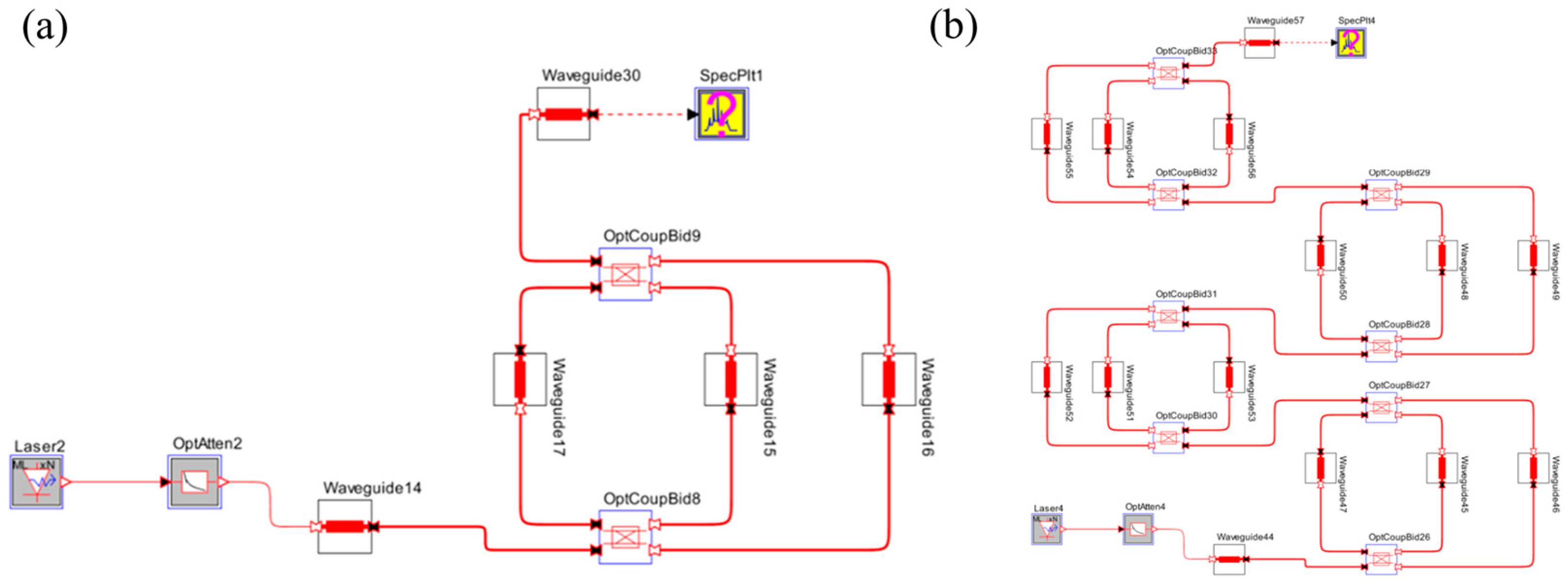
2. Simulation of the Cascaded MZI-Coupled Resonators

To study and design the photonic filter based on cascaded MZI-coupled resonators, we first utilized the finite element method (FEM, RSoft FemSIM) to model the mode profiles of the fundamental transverse electric (TE) mode [28]. Figure 2a shows the simulated model of the Si3N4 waveguides. Two waveguides with widths of 1 μm and 3 μm were selected for the bus and microring resonator waveguides, respectively, with a height of 500 nm. The 1 µm width of the bus waveguide supports single-mode transmission, while the 3 µm width of the resonator waveguide helps to reduce loss by minimizing the overlap between the optical mode and the sidewall, at the cost of the existence of the high-order modes. The target wavelength of photonic filters was set between the telecommunication (C-band, 1530–1560 nm) regime. The simulation profiles are shown in Figure 2b. The confined modes exhibited effective refractive indices of 1.63 and 1.76 for the bus waveguide (width = 1 μm) and resonator waveguide (width = 3 μm), respectively.
Next, the systematic simulation of the cascaded MZI-coupled resonators was analyzed using OptSIM [29], with the architecture illustrated in Figure 3. For the simulated parameters, we evaluated the coupling coefficient and intrinsic loss by fitting with the measured transmission spectra of a single-ring resonator, which will be discussed later. As mentioned, these parameters are critical in determining the extinction ratio and loss in the photonic filters. The radius of microring resonators was set at 100 μm, while the gap between the bus waveguide and the microring resonator was set at 0.5 μm, satisfying the resolution limitations of the I-line stepper lithography [30]. We should note that the feedback waveguide length was initially set to 3πR to match the FSR of the resonators [31,32]. However, due to the differing effective indices, of the bus and resonator waveguides, the interference spectra were nonuniform, with a period of approximately 11 FSRs across the spectrum, as the feedback loop did not have the phase-matched condition [32].
The simulation results are presented in Figure 4. Single-ring and two-, three-, and four-cascaded MZI-coupled resonators resulted in extinction ratios of 9 dB, 18 dB, 27 dB, and 36 dB, respectively. This exhibits a good linear trend with the cascaded number. In addition, a full width at half maximum (FWHM) of 0.125 nm was observed at 1548.55 nm, as shown in Figure 4e.
To further verify the simulated results, we discuss the theoretical model for the MZI-coupled resonators. By analyzing the transfer functions, the transmission response of the single-ring MZI-coupled resonators can be simplified as follows [32], assuming no additional phase change at the coupling regime:
T r e s = 1 κ e 2 1 κ f 2 e i ϕ κ e 2 1 κ p 2 / 2 e i θ 1 κ p 2 / 2 1 κ f 2 e i ( 2 θ + ϕ ) 1 [ 1 κ e 2 1 κ p 2 / 2 e i 2 θ κ e 2 1 κ p 2 / 2 1 κ f 2 e i ( θ + ϕ ) ]
where κ e , κ p , and κ f are the coupling coefficient between waveguides, field loss coefficients at the resonator per round trip, and the field loss coefficient at the feedback loop. θ is the half-circular resonator phase change, and ϕ is the phase change at the feedback loop. Figure 5 shows the normalized transmission spectrum of the designed single-ring MZI-coupled resonator based on Equation (1). We can see that a similar nonuniform spectrum with a period of ≈10 FSRs is identified by this simple model.
The period of the nonuniform spectra is sensitive to the phase difference between the waveguide resonator and the feedback loop and therefore to the relative effective index and the length of the feedback loop. For example, as shown in Figure 6a, the period increased to approximately 15 FSRs when the effective index varied by 3%, from 1.63 to 1.68. Conversely, when the length of the feedback loop was set to 2πR, the period decreased to around 2 FSRs, as shown in Figure 6b.

3. Fabrication Processes

In fabrication, we followed the similar fabrication flow in [30]. First, a wet oxidation process was performed on a four-inch silicon substrate, thermally growing a 4 μm thick silicon dioxide (SiO2) layer. A 500 nm Si3N4 thin film was then deposited via low-pressure chemical vapor deposition (LPCVD). Positive photoresist PFI38 was coated onto the Si3N4 layer, followed by lithography using an I-line (365 nm) stepper. The positive photoresist was then developed using TMAH. Finally, the waveguides were patterned using a high-density plasma (HDP) etching system, with a radio frequency power of 100 W. Figure 7 illustrates the schematics of the fabrication process.
Figure 8 shows the layout design of single-ring and four-cascaded MZI-coupled resonators based on the Si3N4 platform. The widths of the bus and resonator waveguides were set at 1 μm and 3 μm, as used in simulations. To improve uniformity and waveguide quality, dummy patterns were implemented. These patterns help alleviate etching loading, particularly in iso/dense regions, and they were applied only around the resonators where minimizing waveguide loss was most critical. Figure 9 shows the optical microscope (OM) images of the fabricated devices, and the experimental setup is shown in Figure 10. We used a tunable laser as the input source, with a fiber polarization controller (FPC) to adjust the polarization to the TE mode. A pair of lensed fibers was used to optimize coupling, achieving a coupling loss of approximately 6 dB per facet. Lastly, photodetectors recorded optical transmission spectra during wavelength sweeping.

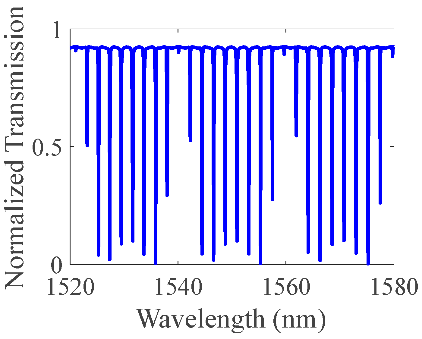
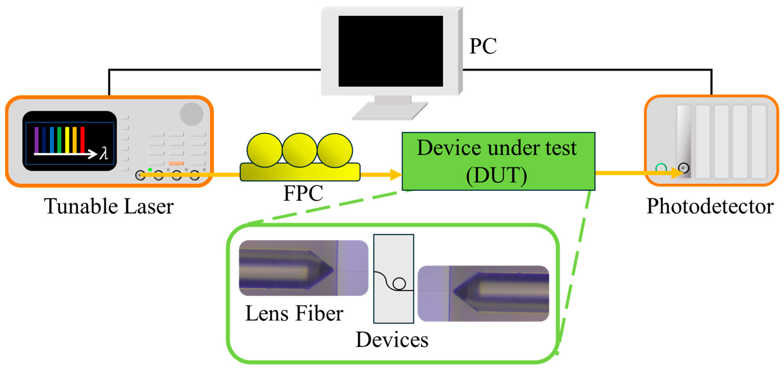
4. Experimental Results

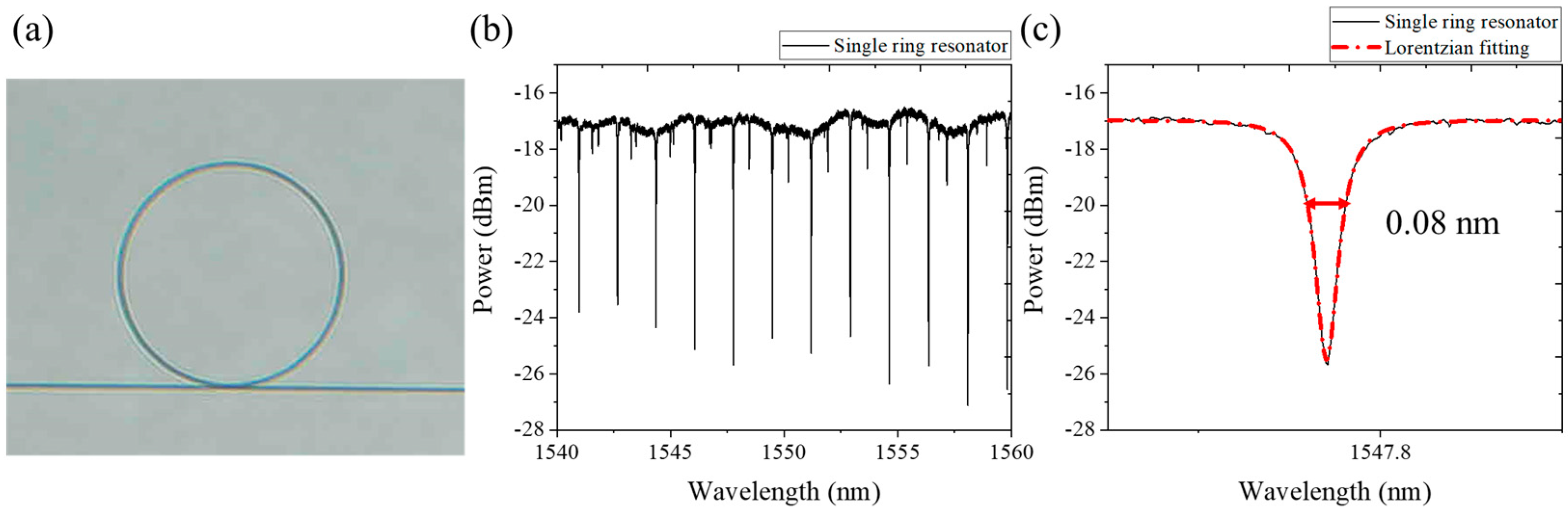
4.1. Insertion Loss and Coupling of a Single-Ring Resonator

To evaluate the performance of cascaded MZI-coupled resonators and their corresponding parameters in the OptSIM model, we first studied the transmission spectrum of a single-ring resonator on the same fabricated device with the cascaded MZI-coupled resonators, ensuring the consistent performance of fabrication processes. Figure 11a shows the fabricated devices, while the measured spectrum is shown in Figure 11b. By fitting the cavity resonance with the Lorentzian function [33], Figure 11c shows the zoomed-in spectrum and the fitted curve. The measured resonance at the through port is given by Equation (2) [33].
T t h r o u g h   p o r t = ( λ λ 0 ) 2 + F S R 4 π 2 ( κ p 2 κ e 2 ) 2 ( λ λ 0 ) 2 + F S R 4 π 2 ( κ p 2 + κ e 2 ) 2
where T t h r o u g h   p o r t represents the transmission response, λ 0 denotes the resonant wavelength, and F S R is the free spectral range of the resonator. κ e 2 and κ p 2 again represent the power coupling ratio between the bus and resonator waveguides and the per-round-trip intrinsic loss within the resonator waveguide [32], respectively. The Q factor of the microring resonator reached 1.1 × 10⁵, corresponding to a waveguide loss of approximately 3 dB/cm, while the measured FSR was 1.71 nm. By fitting with the measured resonance, κ e and κ p were found to be 0.159 and 0.229, in agreement with the above OptSIM simulation. It should be noted that the extinction ratio can be further optimized by achieving critical coupling through a narrower coupling gap. However, this may require a gap smaller than the fabrication limits of stepper lithography.

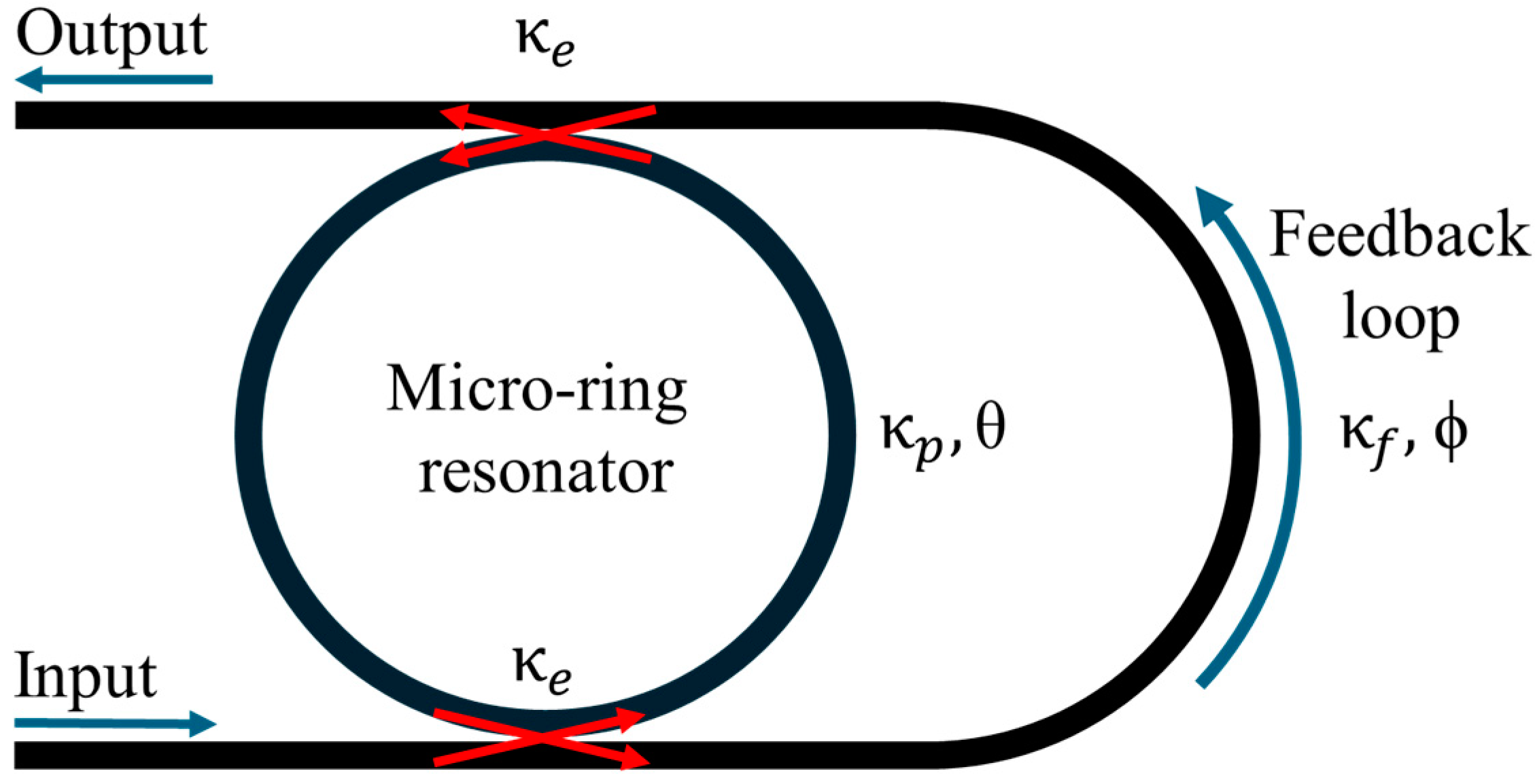
4.2. MZI-Coupled Resonator

Lastly, we characterized the cascaded MZI-coupled resonators. The normalized transmission spectra are shown in Figure 12. First, for the single-ring MZI-coupled resonator, a 9 dB extinction ratio at 1540.25 nm is demonstrated. As for four-cascaded MZI-coupled resonators, a 35 dB extinction ratio at 1534.16 nm was identified, with other resonances also exhibiting high extinction ratios of at least 27 dB, for instance, at 1531.27 and 1567.76 nm, as shown in Figure 12b. Both exhibited similar extinction to that observed in the simulation results. Additionally, the corresponding FWHM values were measured at 0.05 nm and 0.04 nm, indicating a narrower bandwidth, but still in the same order as that of a single-ring resonator. It is important to note that the multi-modes identified from noisy transmission spectra of the four-cascaded MZI-coupled resonators may result from the 3 µm wide waveguide, which supports the existence of higher-order modes in the waveguide resonators. This may also be related to the mismatch in resonance wavelengths of individual resonators caused by fabrication variations. Moreover, the FWHM of the four-cascaded filter was narrower than that from the simulation. Theoretically, FWHM should be broader based on the cascaded scheme, even with a perfect match of individual resonances. This difference could potentially be attributed to the higher waveguide quality of the four-cascaded MZI-coupled resonators. First, with current I-line stepper lithography, even with good uniformity and Q factors of the same order, cavity loss variations may still reach a factor of two [30]. Second, the layout of the four-cascaded MZI resonators may provide a more uniform patterning environment compared to a single-ring MZI-coupled resonator, leading to a higher Q factor. Together, these effects result in a narrower linewidth for the four-cascaded photonic filters.
The comparison of integrated photonic filters is shown in Table 1. Here, we demonstrate the high-extinction photonic filter based on the Si3N4 platform. By designing MZI-coupled resonators, 35 dB extinction was achieved without the need for external thermal tuning or voltage driving. This demonstration provides a solution for configuring high-extinction, band-stop photonic filters, with potential applications in various fields, including optical communication, computing, and quantum technologies. We should note that even though the demonstrated maximal extinction is around 35 dB, the scalability of this architecture opens the possibility for further integration and optimization in complex photonic circuits. Higher extinction ratios could be achieved by incorporating additional MZI-coupled resonators or by fine-tuning the feedback loop with external driving.
Moreover, the demonstrated cascading photonic filters can be further adjusted by utilizing external driving. By altering the effective index of the waveguide resonators through the thermal–optic effect, the resonance wavelength corresponding to the maximum extinction can be tuned. For instance, Figure 13 shows the simulated spectrum of four-cascaded MZI resonators with different effective indices using OptSIM. The resonance corresponding to high extinction changed compared to a single-ring FSR, from 1548.55 nm to approximately 1550.92 nm. However, the synchronization of tuning for the four-cascaded resonators may be necessary.

5. Conclusions

In summary, we demonstrated silicon nitride MZI-coupled resonators fabricated using efficient I-line stepper lithography. By leveraging multi-stage interference, four-cascaded MZI-coupled resonators exhibited a high extinction ratio of 35 dB experimentally, closely agreeing with the simulated value. This approach realizes high extinction without requiring any external driving, showcasing the potential for low-cost, high-performance band-stop photonic filters that are well suited to quantum photonic applications. The scalability and stability of this Si3N4 platform offer additional advantages, providing a versatile pathway for integrating these high-extinction filters into more complex photonic circuits and systems. Furthermore, the fabrication method supports high reproducibility, making it an attractive option for large-scale applications in nonlinear and quantum photonics.

Author Contributions

Conceptualization and methodology, P.-H.W.; investigation, H.-Z.C. and K.-L.H.; data curation, H.-Z.C.; writing—original draft preparation, H.-Z.C.; writing—review and editing, P.-H.W. and H.-Z.C. All authors have read and agreed to the published version of the manuscript.

Funding

This work is supported by the National Science and Technology Council (NSTC), Taiwan, under grant numbers 113-2221-E-A49-191 and 112-2622-8-008-004-.

Institutional Review Board Statement

Not applicable.

Informed Consent Statement

Not applicable.

Data Availability Statement

Data underlying the results presented in this paper are not publicly available at this time but may be obtained from the authors upon reasonable request.

Acknowledgments

P.-H.W. acknowledges the research financial support from the National Science and Technology Council (NSTC), Taiwan, under grant numbers 113-2221-E-A49-191 and 112-2622-8-008-004-. The authors thank the Nano Facility Center (NFC) of National Yang Ming Chiao Tung University (NYCU), Taiwan, for LPCVD Si3N4 layer preparation; Taiwan Semiconductor Research Institute (TSRI) for stepper lithography process and RSoft tool support; and the Optical Sciences Center (OSC) of National Central University (NCU), Taiwan, for fabrication support.

Conflicts of Interest

The authors declare no conflicts of interest.

References

  1. Yacobi, B.G. Semiconductor Materials: An Introduction to Basic Principles; Springer Science & Business Media: Berlin/Heidelberg, Germany, 2003. [Google Scholar]
  2. Grahn, H.T. Introduction to Semiconductor Physics; World Scientific Publishing Company: Singapore, 1999. [Google Scholar]
  3. Schaller, R.R. Moore’s law: Past, present and future. IEEE Spectr. 1997, 34, 52–59. [Google Scholar] [CrossRef]
  4. Ghatak, A.; Thyagarajan, K. Introduction to Fiber Optics; Cambridge University Press: Cambridge, CA, USA, 1998. [Google Scholar]
  5. Jalali, B.; Fathpour, S. Silicon photonics. J. Light. Technol. 2006, 24, 4600–4615. [Google Scholar] [CrossRef]
  6. Kopp, C.; Bernabé, S.; Bakir, B.B.; Fedeli, J.-M.; Orobtchouk, R.; Schrank, F.; Porte, H.; Zimmermann, L.; Tekin, T. Silicon photonic circuits: On-CMOS integration, fiber optical coupling, and packaging. IEEE J. Sel. Top. Quantum Electron. 2010, 17, 498–509. [Google Scholar] [CrossRef]
  7. Kazanskiy, N.L.; Khonina, S.N.; Butt, M.A.; Kaźmierczak, A.; Piramidowicz, R. State-of-the-art optical devices for biomedical sensing applications—A review. Electronics 2021, 10, 973. [Google Scholar] [CrossRef]
  8. Pavesi, L.; Guillot, G. Optical interconnects. In Springer Series in Optical Sciences; Springer: Berlin/Heidelberg, Germany, 2006; Volume 119. [Google Scholar]
  9. Shi, W.; Tian, Y.; Gervais, A. Scaling capacity of fiber-optic transmission systems via silicon photonics. Nanophotonics 2020, 9, 4629–4663. [Google Scholar] [CrossRef]
  10. Ohliger, M.A.; Grant, A.K.; Sodickson, D.K. Ultimate intrinsic signal-to-noise ratio for parallel MRI: Electromagnetic field considerations. Magn. Reson. Med. 2003, 50, 1018–1030. [Google Scholar] [CrossRef]
  11. Dutt, A.; Miller, S.; Luke, K.; Cardenas, J.; Gaeta, A.L.; Nussenzveig, P.; Lipson, M. Tunable squeezing using coupled ring resonators on a silicon nitride chip. Opt. Lett. 2016, 41, 223–226. [Google Scholar] [CrossRef]
  12. Caspani, L.; Xiong, C.; Eggleton, B.J.; Bajoni, D.; Liscidini, M.; Galli, M.; Morandotti, R.; Moss, D.J. Integrated sources of photon quantum states based on nonlinear optics. Light Sci. Appl. 2017, 6, e17100. [Google Scholar] [CrossRef]
  13. Harris, N.C.; Grassani, D.; Simbula, A.; Pant, M.; Galli, M.; Baehr-Jones, T.; Hochberg, M.; Englund, D.; Bajoni, D.; Galland, C. Integrated source of spectrally filtered correlated photons for large-scale quantum photonic systems. Phys. Rev. X 2014, 4, 041047. [Google Scholar] [CrossRef]
  14. Ong, J.R.; Kumar, R.; Mookherjea, S. Ultra-high-contrast and tunable-bandwidth filter using cascaded high-order silicon microring filters. IEEE Photonics Technol. Lett. 2013, 25, 1543–1546. [Google Scholar] [CrossRef]
  15. Piekarek, M.; Bonneau, D.; Miki, S.; Yamashita, T.; Fujiwara, M.; Sasaki, M.; Terai, H.; Tanner, M.G.; Natarajan, C.M.; Hadfield, R.H.; et al. High-extinction ratio integrated photonic filters for silicon quantum photonics. Opt. Lett. 2017, 42, 815–818. [Google Scholar] [CrossRef] [PubMed]
  16. Brunetti, G.; Sasanelli, N.; Armenise, M.N.; Ciminelli, C. High performance and tunable optical pump-rejection filter for quantum photonic systems. Opt. Laser Technol. 2021, 139, 106978. [Google Scholar] [CrossRef]
  17. Kumar, R.R.; Tsang, H.K. High-extinction CROW filters for scalable quantum photonics. Opt. Lett. 2021, 46, 134–137. [Google Scholar] [CrossRef] [PubMed]
  18. Feng, S.; Lei, T.; Chen, H.; Cai, H.; Luo, X.; Poon, A. Silicon photonics: From a microresonator perspective. Laser Photonics Rev. 2012, 6, 145–177. [Google Scholar] [CrossRef]
  19. Soltani, M.; Yegnanarayanan, S.; Li, Q.; Adibi, A. Systematic engineering of waveguide-resonator coupling for silicon microring/microdisk/racetrack resonators: Theory and experiment. IEEE J. Quantum Electron. 2010, 46, 1158–1169. [Google Scholar] [CrossRef]
  20. Hosseini, E.S.; Yegnanarayanan, S.; Atabaki, A.H.; Soltani, M.; Adibi, A. Systematic design and fabrication of high-Q single-mode pulley-coupled planar silicon nitride microdisk resonators at visible wavelengths. Opt. Express 2010, 18, 2127–2136. [Google Scholar] [CrossRef]
  21. Sethi, P.; Kallega, R.; Haldar, A.; Selvaraja, S.K. Compact broadband low-loss taper for coupling to a silicon nitride photonic wire. Opt. Lett. 2018, 43, 3433–3436. [Google Scholar] [CrossRef]
  22. Ahmed, A.N.R.; Shi, S.; Zablocki, M.; Yao, P.; Prather, D.W. Tunable hybrid silicon nitride and thin-film lithium niobate electro-optic microresonator. Opt. Lett. 2019, 44, 618–621. [Google Scholar] [CrossRef]
  23. Zhang, X.-Y.; Zhang, T.; Xue, X.-J.; Zhang, J.-L.; Hong, J.; Wu, P.-Q.; Chen, Q.-Y. Tunable optical ring resonator integrated with asymmetric Mach–Zehnder interferometer. J. Light. Technol. 2010, 28, 2512–2520. [Google Scholar] [CrossRef]
  24. Boyd, R.W.; Gaeta, A.L.; Giese, E. Nonlinear optics. In Springer Handbook of Atomic, Molecular, and Optical Physics; Springer International Publishing: Cham, Switzerland, 2008; pp. 1097–1110. [Google Scholar]
  25. Boggio, J.M.C.; Bodenmüller, D.; Ahmed, S.; Wabnitz, S.; Modotto, D.; Hansson, T. Efficient Kerr soliton comb generation in micro-resonator with interferometric back-coupling. Nat. Commun. 2022, 13, 1292. [Google Scholar] [CrossRef]
  26. Shoman, H.; Jayatilleka, H.; Jaeger, N.A.F.; Shekhar, S.; Chrostowski, L. Measuring on-chip waveguide losses using a single, two-point coupled microring resonator. Opt. Express 2020, 28, 10225–10238. [Google Scholar] [CrossRef] [PubMed]
  27. Zhao, G.; Zhao, T.; Xiao, H.; Liu, Z.; Liu, G.; Yang, J.; Ren, Z.; Bai, J.; Tian, Y. Tunable Fano resonances based on microring resonator with feedback coupled waveguide. Opt. Express 2016, 24, 20187–20195. [Google Scholar] [CrossRef] [PubMed]
  28. RSoft FemSIM. RSoft Products.20; Synopsys, Inc.: Sunnyvale, CA, USA, 2024. [Google Scholar]
  29. OptSIM. RSoft Products.32; Synopsys, Inc.: Sunnyvale, CA, USA, 2024. [Google Scholar]
  30. Huang, Y.-K.; Wang, P.-H. CMOS-compatible 6-inch wafer integration of photonic waveguides and uniformity analysis. Opt. Express 2024, 32, 7197–7206. [Google Scholar] [CrossRef] [PubMed]
  31. Cai, L.; Lu, Y.; Zhu, H. Performance enhancement of on-chip optical switch and memory using Ge2Sb2Te5 slot-assisted microring resonator. Opt. Lasers Eng. 2023, 162, 107436. [Google Scholar] [CrossRef]
  32. Zhou, L.; Poon, A.W. Electrically reconfigurable silicon microring resonator-based filter with waveguide-coupled feedback. Opt. Express 2007, 15, 9194–9204. [Google Scholar] [CrossRef]
  33. Xiao, S.; Khan, M.H.; Shen, H.; Qi, M. Modeling and measurement of losses in silicon-on-insulator resonators and bends. Opt. Express 2007, 15, 10553–10561. [Google Scholar] [CrossRef]
  34. Choure, K.K.; Saharia, A.; Mudgal, N.; Pandey, R.; Prajapat, M.; Maddila, R.K.; Tiwari, M.; Singh, G. Implementation of all-optical single qubit gates using Si3N4 based micro ring resonator. Opt. Laser Technol. 2024, 170, 110263. [Google Scholar] [CrossRef]
  35. Feng, J.; Akimoto, R.; Hao, Q.; Zeng, H. Three-dimensional cross-coupled silicon nitride racetrack resonator-based tunable optical filter. IEEE Photonics Technol. Lett. 2017, 29, 771–774. [Google Scholar] [CrossRef]
  36. Wang, M.; Chen, X.; Khan, U.; Bogaerts, W. Programmable wavelength filter with double ring loaded MZI. Sci. Rep. 2022, 12, 1482. [Google Scholar] [CrossRef]
  37. Sun, Q.; Zhou, L.; Lu, L.; Zhou, G.; Chen, J. Reconfigurable high-resolution microwave photonic filter based on dual-ring-assisted MZIs on the Si3N4 platform. IEEE Photonics J. 2018, 10, 1–12. [Google Scholar] [CrossRef]
  38. Cheng, W.; Lin, D.; Wang, P.; Shi, S.; Lu, M.; Wang, J.; Guo, C.; Chen, Y.; Cang, Z.; Tian, Z.; et al. Tunable bandpass microwave photonic filter with largely reconfigurable bandwidth and steep shape factor based on cascaded silicon nitride micro-ring resonators. Opt. Express 2023, 31, 25648–25661. [Google Scholar] [CrossRef] [PubMed]
Figure 1. Schematic diagram of MZI-coupled resonator structure.
Photonics 11 01055 g001
Figure 2. (a) Simulation modal of the Si3N4 waveguides; (b) simulated mode profiles of TE modes with the waveguide width of 1 μm and 3 μm, respectively.
Photonics 11 01055 g002
Figure 3. Exemplary schematics of (a) single-ring and (b) 4-cascaded MZI-coupled resonators.
Photonics 11 01055 g003
Figure 4. Simulated transmission spectra of (a) single-ring and (b) 2-, (c) 3-, and (d) 4-cascaded MZI-coupled resonators. (e) The zoom-in spectrum of a resonance in (d).
Photonics 11 01055 g004
Figure 5. Simulated transmission spectrum of a single-ring MZI-coupled resonator.
Photonics 11 01055 g005
Figure 6. Simulated transmission spectra of a single-ring MZI-coupled resonator by tuning the parameters of the feedback loop with (a) effective index = 1.68 and (b) feedback length = 2πR.
Photonics 11 01055 g006
Figure 7. The fabrication process of cascaded MZI-coupled resonators.
Photonics 11 01055 g007
Figure 8. Layout designs of (a) single-ring and (b) 4-cascaded MZI-coupled resonators.
Photonics 11 01055 g008
Figure 9. OM images of (a) single-ring and (b) 4-cascaded MZI-coupled resonators.
Photonics 11 01055 g009
Figure 10. Experimental setup for optical characterization.
Photonics 11 01055 g010
Figure 11. (a) OM image of the single-ring resonator; (b) measured transmission spectra of the single-ring resonator; (c) zoomed-in spectrum and fitted curve.
Photonics 11 01055 g011
Figure 12. Transmission spectra and zoomed-in spectra of (a) single-ring and (b) 4-cascaded MZI-coupled resonators.
Photonics 11 01055 g012
Figure 13. Simulated transmission and the zoomed-in spectra of 4-cascaded MZI resonators with difference effective indices.
Photonics 11 01055 g013
Table 1. Comparison of schemes for integrated photonic filters.
Photonic Filter StructurePlatformsExternal DrivingFWHMPattern DefinitionMax. Extinction Ratio
Ring resonator [20]Si3N4WithoutN.A.Electron-beam10 dB
Ring resonator [30]Si3N4WithoutN.A.I-line stepper15 dB
Ring resonator [34]Si3N4Without0.2 nmElectron-beam20 dB
Ring resonator [22]Si3N4+ thin-film lithium niobateWith0.013 nmElectron-beam27 dB
MZI + Ring resonator [35]Si3N4WithN.A.Electron-beam14 dB
MZI + Ring resonator [26]SOIWith 0.025 nmDeep UV29 dB
MZI + Ring resonator [27]SOIWithN.A.I-line stepper31 dB
MZI + Double-ring [36]SOIWithoutN.A.Deep UV30 dB
Ring + Multi-stage filter [15]SOIWithoutN.A.Deep UV86 dB
CROW filter [17]SOIWithout0.14 nmDeep UV96 dB
Dual-ring-assisted MZIs [37]Si3N4With0.06 nmTriPleX ADS18 dB
Double-ring [38]Si3N4With0.016 nmTriPleX ADS34 dB
MZI + Ring resonator
(this work)
Si3N4Without0.04 nmI-line stepper35 dB
Source: Self-elaboration based on the references mentioned.
Disclaimer/Publisher’s Note: The statements, opinions and data contained in all publications are solely those of the individual author(s) and contributor(s) and not of MDPI and/or the editor(s). MDPI and/or the editor(s) disclaim responsibility for any injury to people or property resulting from any ideas, methods, instructions or products referred to in the content.

