Article

Selective Ablation and Laser-Induced Periodical Surface Structures (LIPSS) Produced on (Ni/Ti) Nano Layer Thin Film with Ultra-Short Laser Pulses

by
Biljana Gaković
1,*,
Suzana Petrović
1,
Christina Siogka
2,
Dubravka Milovanović
3,
Miloš Momčilović
1,
George D. Tsibidis
2 and
Emmanuel Stratakis
2
1
Vinča Institute of Nuclear Sciences, University of Belgrade, 11000 Belgrade, Serbia
2
Institute of Electronic Structure and Laser (FORTH), 711 10 Heraklion, Greece
3
Institute of General and Physical Chemistry, 11000 Belgrade, Serbia
*
Author to whom correspondence should be addressed.
Photonics 2024, 11(11), 1054; https://doi.org/10.3390/photonics11111054
Submission received: 20 September 2024 / Revised: 26 October 2024 / Accepted: 7 November 2024 / Published: 10 November 2024

Abstract

:
The interaction of ultra-short laser pulses (USLP) with Nickel/Titanium (Ni/Ti) thin film has been presented. The nano layer thin film (NLTF), composed of ten alternating Ni and Ti layers, was deposited on silicon (Si) substrate by ion-sputtering. A single and multi-pulse irradiation was performed in air with focused and linearly polarized laser pulses. For achieving selective ablation of one or more surface layers, without reaching the Si substrate, single pulse energy was gradually increased from near the ablation threshold value to an energy value that caused the complete removal of the NLTF. In addition to single-pulse selective ablation, the multi-pulse USLP irradiation and production of laser-induced periodic surface structures (LIPSSs) were also studied. In the presented experiment, we found the optimal combination of accumulated pulse number and pulse energy to achieve the LIPSS formation on the thin film. The laser-induced morphology was examined with optical microscopy, scanning electron microscopy, and optical profilometry. To interpret the experimental observations, a theoretical simulation has been performed to explore the thermal response of the NLTFs after irradiation with single laser pulses.

1. Introduction

Nickel–titanium (Ni/TI) nano layer thin film (NLTF) is a class of composite material fabricated from alternating nano meter-scale Ni and Ti layers. Multi-layer thin films of Ni/Ti have found applications such as super mirrors for neutron optics, as well as reactive films for micro-joining solutions [1,2,3]. Ti/Ni multi-layers have become ideal candidates for neutron optics and soft X-ray optics due to their excellent contrast factor and their tunable properties, particularly regarding reflectivity and polarization efficiency. They also show composition-modulated structures, which are beneficial for the preparation of Ni-Ti shape memory alloy films [4].
The laser processing of materials, as well as NLTFs, is a non-contact widespread method for their modification. In the pulsed laser systems, the pulse duration time can be roughly divided into three domains: ultra-short (from a few femtoseconds to ten picoseconds), short (higher than ten picoseconds), and long (nanoseconds and microseconds). The appropriate laser system for the NLTFs processing is dependent on the application [5,6,7]. Thermal effects, such as the melting of the surface layer as well as the substrate, and the ejection of molten material, are generally dominant surface features after irradiation by a laser with a pulse duration above 10 picoseconds. Consequently, the boundary between the irradiated and non-irradiated areas is not clearly distinguished. In the case of ultra-short laser pulses (USLP), the more precise processing of NLTFs can be achieved. Irradiation with these pulses allows the ultrafast transfer of photons energy into the material. This is important because of the reduced heat diffusion to the surrounding regions of the processed area and almost no formation of a heat-affected zone (HAZ) [8,9]. Additionally, ultrafast laser processing enables the achievement of a special type of ablation of a target surface—selective ablation [10,11,12,13,14]. Selective ablation is particularly important for the treatment of NLTF when the superficial layer needs to be removed only from a part of the surface. Furthermore, only specific USLP can achieve selective ablation and selectively remove one and sometimes multiple layers from the surface of a multi-layer film. Selective ablation can only be achieved at specified values of the laser beam’s properties for a given material [15,16].
On the surface of almost any material, a USLP irradiation can produce ripples or periodical structures. They are mainly caused by exposing the surface of the sample to the radiation of multiple USLP pulses. In the literature, this phenomenon is known as “laser-induced periodic surface structures” (LIPSSs) [17,18]. It is generally accepted that two types of LIPSSs can be produced: low spatial frequency LIPSS (LSFL) and high spatial frequency LIPSS (HSFL). The period value, Λ, of LSFL, registered on metals, is close to the laser light wavelength λ and is mainly oriented perpendicular to the laser polarization, while in the case of HSFL periodicity Λ is less than ½λ, and is oriented parallel or sometimes normal to the laser polarization [18]. Which type of LIPSS is formed also depends on the material properties, laser pulse parameters, and on the number of accumulated pulses [19,20,21,22].
The sample used in this study is created from two alternately deposited metal nano layers. The presence of an interface between the nano layers, as well as their different physical–chemical characteristics, affects both selective ablation and LIPSS formation.
The interaction of ultrafast laser pulses with Nickel/Titanium (Ni/Ti) thin film was investigated in the presented study. The NLTF, composed of ten alternating Ni and Ti bi-layers, were deposited by ion-sputtering on a silicon (Si) substrate. The experiment was conducted with single- and multi-pulse irradiation in air using a focused and linearly polarized laser beam (wavelength of 1026 nm and pulse duration of 170 fs). For achieving selective ablation, the single-pulse energy was gradually increased from near the ablation threshold value to a level that completely removed the NLTF. The pulse energy value for LIPSS creation was chosen to be close to the ablation threshold of the NLTF. After irradiations, microscopy, energy-dispersive X-ray spectroscopy, and optical profilometry were used to investigate the surface features, the depth of produced craters, and the alterations in elemental composition generated by the incident laser beam. A theoretical simulation has been carried out to investigate the thermal response of the NLTF following irradiation with single laser pulses to clarify the results of the experiment.

2. Experimental

2.1. Thin Film Preparation and Characterization

The Ni/Ti multi-layer structures were prepared by a commercial Balzers Sputtron II vacuum system using 1.5 keV argon ions and 99.9% pure Ni and Ti targets. The depositions were carried out under a chamber base pressure of approximately 1 Å~10−6 mbar and argon partial pressure during deposition of 1 Å~10−3 mbar. The substrate was an n-type silicon (100) wafer (0.5 mm thick) held at ground potential during the deposition. It was cleaned by an HF etching and dipped in deionized water before mounting in the deposition chamber. Prior to layers deposition, the substrate was additionally cleaned by ion sputtering. Multi-layers were deposited in a single vacuum run at ca. 0.13 nm s−1 for Ni and ca. 0.1 nm s−1 for Ti, without heating the substrate. The first deposited layer on the substrate was Ti and the topmost Ni. The experimental sample with a total thickness of 440 nm was composed of 20 single layers with thicknesses of 22 nm each. In the text below, the sample is marked as 10 × (Ni/Ti).
To achieve the selective ablation of NLTF, we irradiated the sample with individual laser pulses of different pulse energies. Multiple pulses with constant pulse energy (Ep) were used to study the evolution of LIPSS. It is generally accepted in pulsed laser modification/damage description that for the comparison of radiation effects the corresponding pulse fluence (Fp) is used instead of pulse energy. A common unit used in the literature for fluence is [J/cm2], and it was calculated from the laser pulse energy divided by the laser beam sectional area. In the case of the Gaussian laser beam Fp = Ep/A, A = π(r1/e))2 where r1/e is the beam radius, at which the beam intensity is 1/e of the maximal fluence Fo.
The surface characteristics of the sample, before and after laser processing, were analyzed first using optical microscopy and then in more detail using scanning electron microscopy (SEM-JEOL JSM-7500F). The LIPSS characteristics were determined by two-dimensional fast Fourier transform (2D-FFT) analysis of the corresponding SEM images using the open-source software Gwyddion version 2.64 (http://gwyddion.net/, accessed on 14 May 2024). Changes in the topography of the irradiated surfaces were analyzed using a non-contact optical profilometry (Zygo NewView 7100 Zygo Corporation), and characteristic surface parameters were calculated using MetroPro software (version 7.15.0). The vertical accuracy of measurement was 0.1 nm. The surface parameter determination accuracy was <4.5%. The laser modifications and measurements were performed in fivefold.

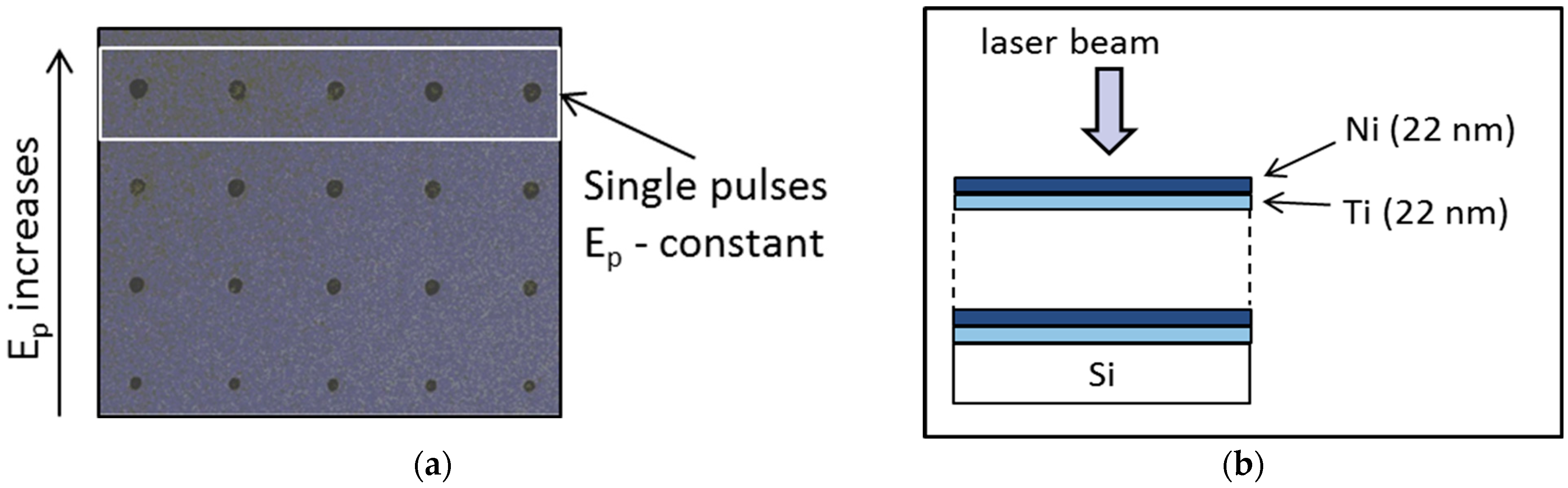
2.2. Laser Irradiation Parameters

The laser used in the experiment was a potassium gadolinium tungsten (Yb:KGW) laser, operating at wavelength λ = 1026 nm, pulse duration τ = 170 fs, and the repetition rate R = 1 kHz. The spatial distribution was Gaussian with 1/e radii of 22.3 μm. The laser beam was focused on the sample surface through a microscope. The focusing of the laser beam, and the position of the places for single- and multi-pulse irradiation, were achieved with a three-dimensional computer controlled motorized stage.
The sample irradiations were performed by the single- and multi-pulses delivered on the newly exposed surface in the air at laboratory conditions. During the experiment, the single-pulse energy was gradually increased from a level without any observable surface changes to the level at which the complete NLTF was removed. While pulse energy varied from line to line, consistent pulse energy was delivered five times in a line (Figure 1). This was conducted to make sure that there was no accidental deviation from the set pulse energy value. Multi-pulse irradiation was performed by 1, 2, 3, 5, 10, 20, and 50 successive pulses at a constant pulse energy. The scheme was similar to the single-pulse irradiation pattern. Each line consists of constant pulse number. In both cases, the distance between the spots and lines was 200 µm.

3. Results and Discussion

We investigated how the gradual varying of laser pulse energy affects the NLTF surface. SEM micrographs revealed if ablation, i.e., the removal of material, occurred and provided the dimension values of modified areas, such as the spot diameters or ripples periods, thus contributing to the further understanding of the nature of the ablated areas. From this information, it could be concluded if the selective ablation of the surface layer(s) of the NLTF occurred. The profilometry measurements provided additional information regarding the depth of the ablated areas/craters.

3.1. Single Pulse Irradiation—Selective Ablation of 10 × (Ni/Ti)

The 10 × (Ni/Ti) sample was irradiated by single pulses that carried different amounts of energy to reach the conditions for the selective ablation of a surface layer from the NLTF. The value of the pulse energy increased gradually from 0.46 to 12.56 μJ, i.e., 0.03 to 0.8 J/cm2 of pulse fluence. The start of ablation was observed at 0.07 J/cm2, in the center of altered region (Figure 2a). As the pulse energy increased, the area of surface ablation increased too. Primarily, after the laser action of 0.08 J/cm2, several relatively small, ablated areas can be seen at the central part of the modified area, in Figure 2b. Further laser modification, with 0.09 J/cm2 and up to 0.4 J/cm2 fluence, led to the ablation in the form of relatively homogeneous circular areas on the surface. These modified areas were characterized by their flat bottoms and distinct edges (Figure 2c–g). Therefore, the process that occurred could be designated as one-step selective ablation. New topography features appeared at fluence values of 0.5 J/cm2 and higher, shown in Figure 2h. An additional ablated region was observed in the center (Figure 2h)—which was probably the two-step selective ablation. However, the SEM analysis results were not sufficient to conclude that one-step and two-step selective ablation of the NLTF surface layer occurred. The depth dimensions and surface parameters, like roughness, e.g., the flatness of ablated areas, was necessary for further investigation. These measurements were performed using a non-contact optical profiler.
As the result of irradiation with 0.1 J/cm2 laser fluence, the flat bottom with constant depth was registered, as shown in Figure 3(a1), and the corresponding measured depth was 21 nm (Table 1), confirming that single-step ablation occurred. After irradiation by higher fluences, up to and including 0.4 J/cm2, the two characteristic crater depth values can be distinguished, e.g., minimal and maximal depth, with the respect to the undamaged surface of NLTF (Table 1). The maximal depth value at the spot periphery was slightly higher than the thickness of the first layer. The depth of the central part was close to the thickness of the first layer. This could explain the presence of an interface between Ni and Ti. Namely, it is known that, under the influence of laser radiation, the intermixing of layers occurs with the formation of an alloy at the interface [22]. In general, its formation and properties depend on the laser parameters and the thickness of the layers. In this work, we did not investigate that phenomenon. However, it can be concluded that the first layer was completely ablated from the remaining 10 × (NiTi).
After the irradiation with 0.5 J/cm2 laser fluence, the topography was characterized by two distinguished ablated areas, which can be observed in Figure 2h. The profilometry results confirmed that ablation was achieved in two stages (Table 1). The first value of ablation step/stage (ablated depth) was again close to the thickness of the first nano layer (approximately 23 nm), and the following ablation depth at the following stage was almost the same as the value of two nano layers (approximately 41 nm). The NLTF beneath was not ablated, and this ablation process/mechanism can be confirmed as the two-step selective ablation.
Laser ablation with USLPs is a technology widely used in many applications, such as surface micro- and nano-patterning, cutting, drilling, laser surgery, mass spectrometry, controlled production of nanoparticles with narrow size distributions, and well-controlled compositions. Understanding the mechanisms that lead to ablation in detail remains a challenge because of the complexity of the processes taking place [8,12,23], the variety of species involved, and the range of length and time scales covered. It is generally accepted that removal of the surface material, in the form of shallow flat craters, with sharp edges, is the consequence of photomechanical ablation–spallation [14,15,16]. Another consequence of this kind of ablation is the possibility of selective ablation of the surface nano layer from the rest of NLTFs. A short physical explanation follows: (i) in metals, the energy of a USLP merges mainly to electrons through the direct absorption of laser energy and extremely fast heating of electrons, the electrons collide with lattice heating them; (ii) the short pulse laser irradiation may cause the rapid heating and melting of localized surface of internal regions of the target, and produce sharp temperature gradients leading to rapid quenching of the transiently melted material; (iii) as metals are strongly absorbing materials, a combination of the shallow depth of the laser energy deposition with the high thermal conductivity of the material can lead to cooling rates even exceeding 1012 K/s, and the laser energy deposition is confined within the thin surface layer [24]; (iv) the laser-induced cooling combined with the generation and relaxation of strong compressive stresses generated by the fast laser heating of the absorption region create the conditions for the formation of unusual metastable phases that are difficult, if not impossible, to produce with lasers with longer pulses; (v) the interaction of the laser-induced compressive stresses with the free surface of the metal sample can result in the generation of a tensile wave that is sufficiently intense to cause the formation subsurface voids and, the growth and diffusion of the voids may lead to the separation and ejection of a top layer from the target [16,24]. Analogous to the term “spallation”, which is commonly used to describe the dynamic fracture that results from the reflection of a shock wave from the back surface of a sample [10], is the material ejection driven by the relaxation of laser-induced stresses, commonly referred to as “photomechanical spallation”. A further increase in the laser fluence results in a transition to a different ablation regime, commonly referred to as “phase explosion” [25]. In this regime, the melted surface region of the irradiated target is overheated above the limit of thermodynamic stability of the liquid phase, leading to the rapid decomposition of the overheated melted material into a mixture of vapor and liquid droplets.
Accordingly, it was justified to conclude that in this study the selective ablation–spallation started and ended at the specific range of USLP fluences. Processing with pulses of higher fluences did not result in selective ablation of the upper layer. The formed craters, in the fluence range from 0.09 to 0.4 J/cm2, were characterized by almost flat bottoms, while at 0.5 J/cm2 a two-step profile is observed. The height of the first one was near to the step value of single-step ablation, but in the central region, the ablation depth value was almost the same as the two nano layers of NLTF. Therefore, it could be acknowledged as two-step ablation. Irradiation with a laser fluence of 0.6 J/cm2 and above resulted in differently pronounced morphology. The irregular surface topography of the bottom of the ablated regions under these experimental conditions can be explained as the consequence of phase explosion [25].

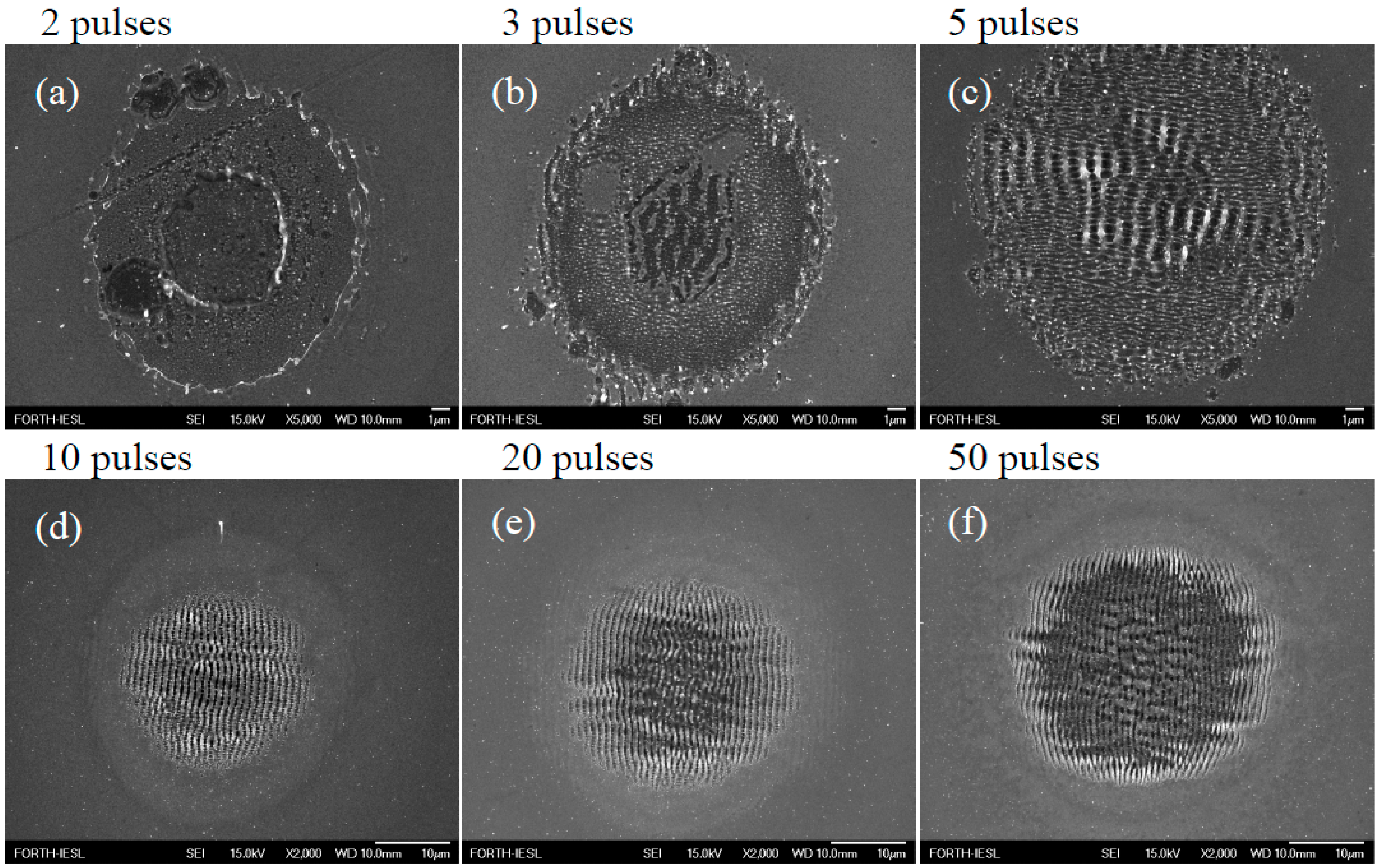
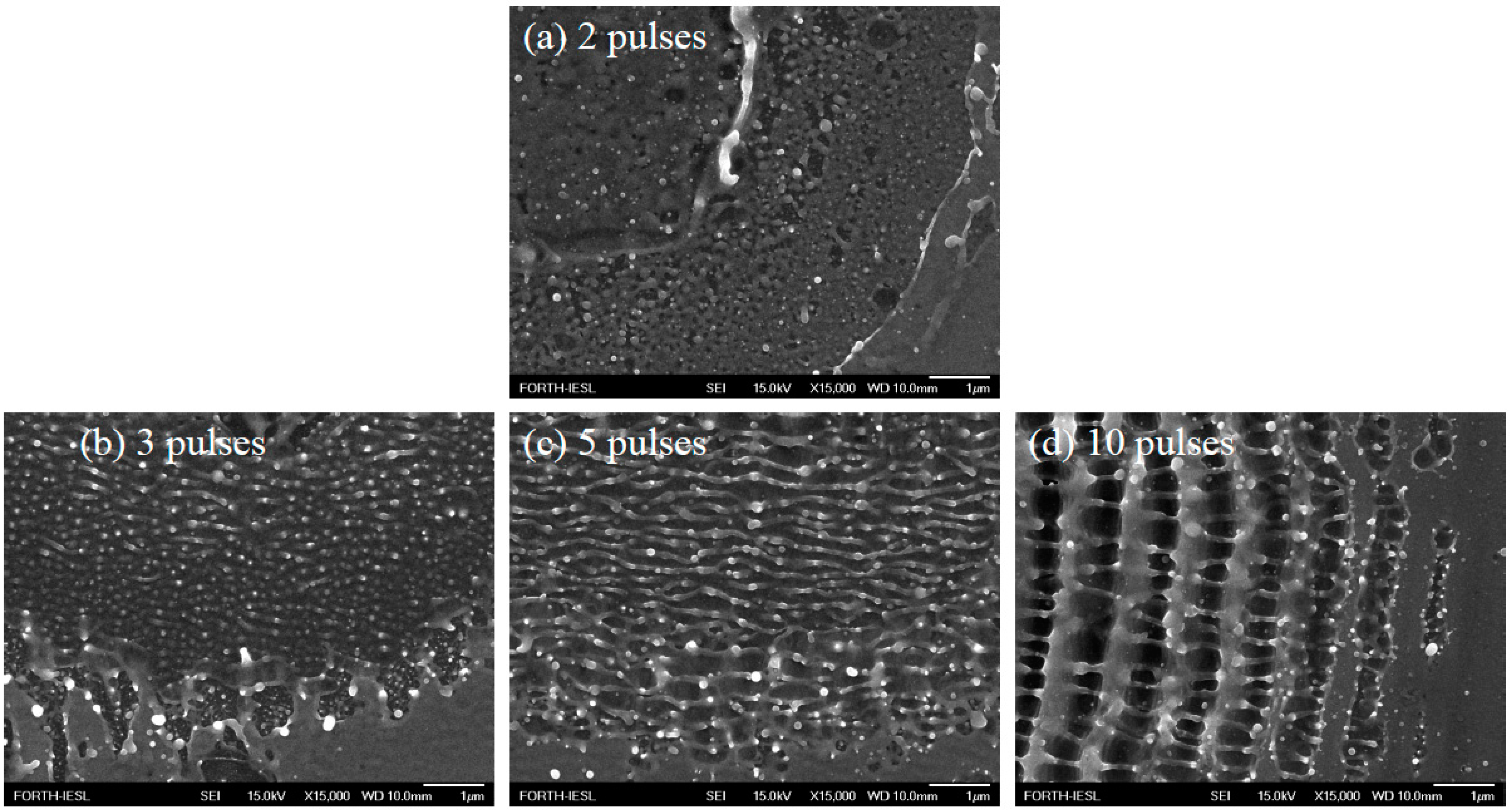
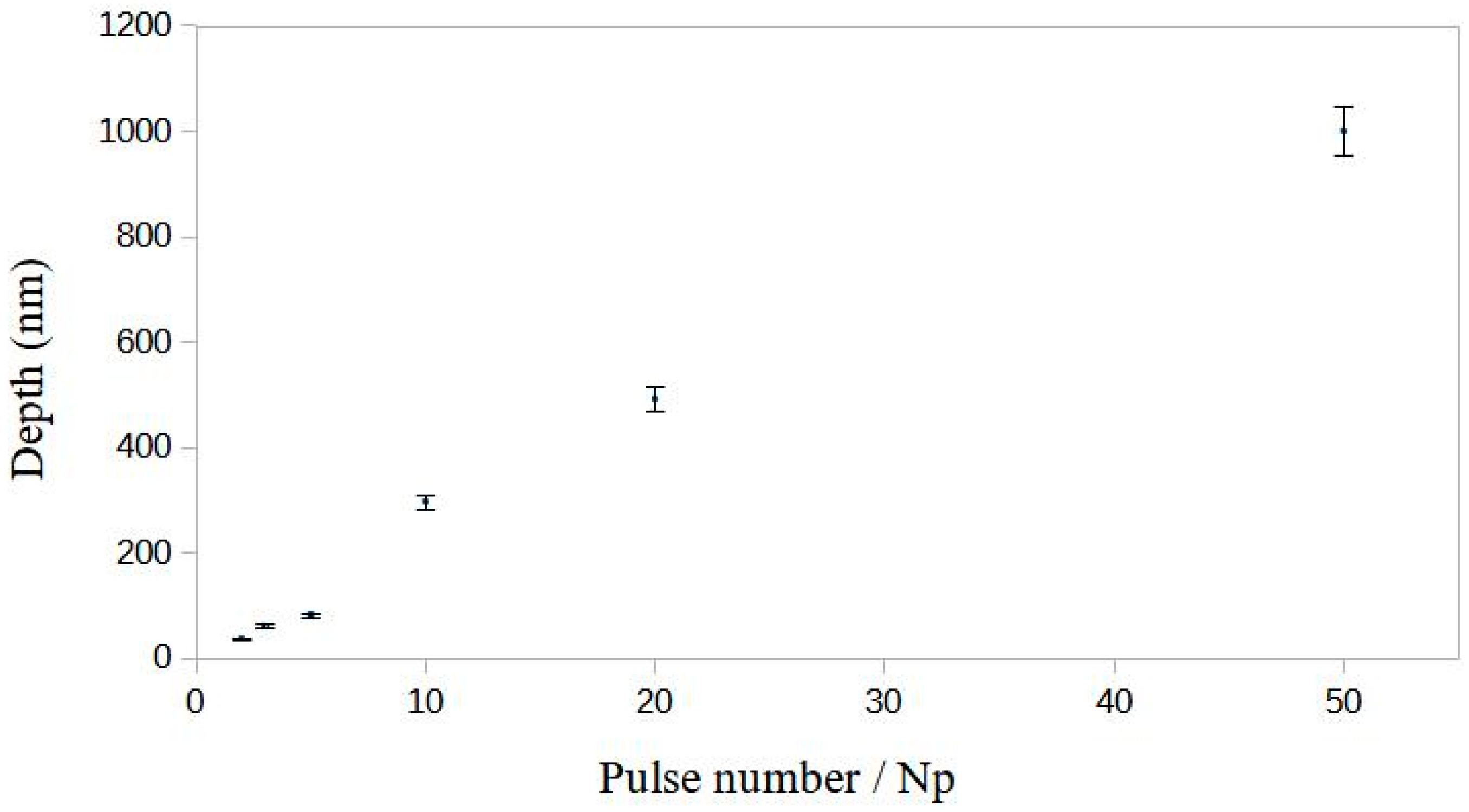
3.2. Multi-Pulse Irradiation—LIPSS Formation on 10 × (Ni/Ti)

To achieve surface topography with periodic structure, the irradiation was conducted with an increasing pulse count, from 2 up to 50 successive pulses at the same surface area and the same fluence value. The LIPSSs’ formation was detected after three pulses, and their evolution can be followed on SEM micrographs. The surface of the NLTF after N = 2, 3, 5, 10, 20 and 50 pulses are presented in Figure 4a–f, while SEM micrographs with more details are shown in Figure 5a–d.
After two-pulse laser action, in the zone between the two sharp edges, the features resembling the effects of two-step ablation (Figure 4a), with the separation of nanoparticles, with dimensions of about 80 nm, was registered (Figure 5a). Further evolution of the surface features after three applied pulses could be attributed to material self-organization and the start of HSFL formation at the periphery (Figure 4b). The LSFL were formed in the spot center, where the pulse fluence has had maximal value, causing the ablation of some of the layers in the areas with the periodic structures (Figure 4b). At the same time, the outer edge of the well-defined circular contour during single-pulse irradiation was disturbed here. The formed HSFL structure did not show a fine regularity, which was made of nanoparticles arranged in lines (Figure 5b). By using irradiation with five pulses, the appearance of both types of periodic structures parallel to HSFL and normal to LSFL to the laser polarization with high regularity was achieved (Figure 4c and Figure 5c). The regularity of the LIPSS is directly related to the value of the length of surface plasmon polariton (LSPP) if one assumes that LIPSS is formed by the excitation of surface plasmon polariton (SPP) on the laser-irradiated surface [19,26,27]. Thin film components (Ti and Ni) have LSPP values below 10 μm and thus belong to the metals with regular LIPSS formation [26]. The periodicity of the observed HSFL structure parallel to the laser polarization was measured to be Λ = (250 ± 30) nm. By applying 10 pulses, the dominant formation of LSFL structures was achieved on the entire surface of the spot (Figure 4d). The HSFL structure remained on the periphery, but only between LSFL periods. These seemed like thin filaments interconnecting LSFLs and were perpendicular to them (Figure 5d).
With a further increase in the number of applied pulses (20 and 50 pulses), the ablation was intensified, which led to the complete removal of the thin film and the formation of grooves, especially in the central part of the spot (Figure 4e,f). Well-defined LSFL structures were created at the periphery of the irradiated area, so that by increasing the number of pulses, the HSFL structures gradually disappeared between LSFL periods. The periodicity values Λ of LSFL structures were Λ = (914 ± 97) nm, after 10 pulses, Λ = (920 ± 50) nm, after 20 pulses and after the 50 pulses laser irradiation Λ = (918 ± 62) nm, which indicates that the number of applied pulses does not affect the periodicity. The periodicity was obtained from the 2D-FFT analyses of the SEM micrographs.
The maximal depths of the craters, produced after multi-pulse irradiations, were determined, and presented in a diagram (Figure 6). The maximal depth at the central part of the craters, after N = 20 and 50 applied pulses, was 492 nm and 1000 nm, respectively.

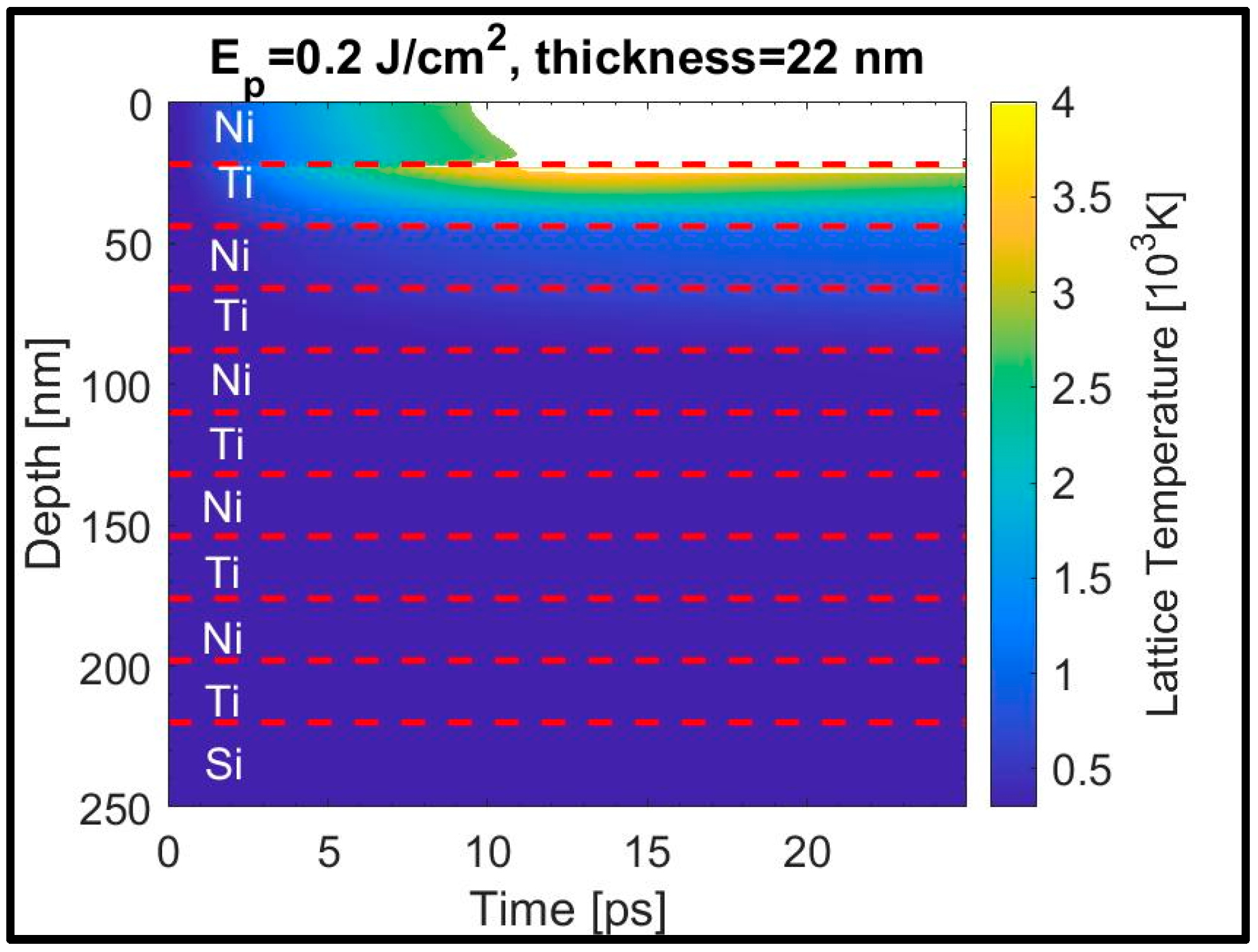
4. Temperature Evolution After Single-Pulse Irradiation

To interpret the aforementioned experimental results, a multiscale physical model was used to describe the underlying processes following irradiation of the multi-layered stack with the laser pulses. In Figure 7, the temporal evolution of the thermal response of the irradiated stack is illustrated [28,29]. As described in previous reports [28,29], a two-temperature model is used to describe the excitation of electrons and the relaxation processes in the multi-layered stack:
C e ( i ) T e ( i ) t = z k e ( i ) T e ( i ) z G e L ( i ) T e ( i ) T L ( i ) + S ( i ) ( z , t ) [ S ( i ) = 0 ,   for   i > 1 ] C L ( i ) T L ( i ) t = z k L ( i ) T L ( i ) z + G e L ( i ) T e ( i ) T L ( i )
S ( 1 ) ( z , t ) = α ( 1 R T ) 4 log 2 F π τ p exp 4 log 2 t 3 τ p τ p 2 exp ( α z )
In Equations (1) and (2), T e i ( T L i ) stand for the electron (lattice) temperature of layer i (odd-numbered layer corresponds to Ni while even-numbered layered corresponds to Ti films). The thermophysical properties of the materials such as electron and lattice heat capacity, ( C e i , C L i ), electron and lattice heat conductivity ( k e i = k e 0 i B i T L i / A i T e i 2 + B i T L i , k L i = 0.01 k e i ), electron–phonon coupling strengths ( G e L i ) and the model parameters used in the simulations are listed in Table 2. While Equation (2) provides the general expression of the form of the source term due to material heating with a pulsed laser that includes the absorption coefficient α, the reflectivity R and the transmission coefficient T of the material, the transfer matrix method [30] is used to compute the optical properties. In principle, heat transfer is only expected between the top 2–3 layers (see also [28,29]), while optical excitation of the rest of the layers (except for the top layer) is negligent.
Equations (1) and (2) are solved by using an iterative Crank–Nicolson scheme based on a finite-difference method. For initial conditions, we choose thermal equilibrium at Te(z,t = 0) = TL(z,t = 0) = 300 K. Adiabatic boundary conditions are considered on the surface (at z = 0, k e N i T e N i z = k L N i T L N i z = 0) and the back of the complex structure. Furthermore, at the interface between two layers, the following conditions are applied: T e N i = T e T i and T L N i = T L T i , k L N i T L N i z = k L T i T L T i z , k e N i T e N i z = k e T i T e T i z . The evaluation of the thermal response of the material following irradiation with single pulses is performed through the correlation of the simulation results with the measured ablation. As noted in previous reports, ablation may be associated with the lattice temperature exceeding the condition (~0.90 Tcritical where Tcritical is the critical point temperature [31,32]).
The theoretical results indicate that the conditions used in the experiment are sufficient to remove the upper layer (Ni), while a part of the second layer (Ti) was also partially ablated (i.e., the white region in Figure 7 illustrates the ablated portion of the irradiated material). By contrast, while the temperature rises in the second layer to levels that induce a phase transition, the temperature in the third (and the subsequent) layers did not rise significantly. However, in the results shown in Figure 7, characteristic for one pulse, similar conclusions were deduced when repetitive irradiation was applied on the resulting pattern (i.e., following ablation, mass displacement and resolidification [28]). Although a more detailed analysis requires an investigation of the pulse-by-pulse deformation of the multi-layered material, the conclusions resulting from the above analysis are sufficient to show that each pulse led to the ablation of the (then) upper layer while the thermal response of the two underlying layers contributed to the characteristics of the induced topography.
Table 2. Simulation parameters for Ti and Ni.
ParameterTiNi
GeL [Wm−3K−1]Fitting [29,33,34]Fitting [35]
Ce [Jm−3K−1]Fitting [29,33,34]Fitting [35]
CL [Jm−3K−2]2.3521 × 10⁶ [29,33,34]Fitting [35]
ke0 [Jm−1s−1K−1]21.9 [29,33,34]90 [35]
Tmelting [K]1941 [29,34]1728 [35]
Tcritical [K]15,500 [29,34]8500 [35,36]
A [s−1K−2]Fitting [29]0.59 × 10⁷ [35]
B [s−1K−1]Fitting [29]1.4 × 10¹¹ [35]

5. Conclusions

Along with the laser treatments on multi-layer thin films to form alloy and for laser-induced surface strengthening, precise laser ablation on a micro level could increase the potential applications of multi-layer thin films in nanotechnology, aerospace, biomedical devices, and neutron optics. Experiments involving nano-layered thin films and their processing by ultra-short laser pulses are generally crucial to expanding the applications and validating the existing theory.
In this work, ablation of nano layer 10 × (Ni/Ti) with USLP was studied. The most distinguished selective ablation, with flat bottom of the craters was achieved at the fluence value of 0.09 and 0.1 J/cm2. Further increase of the fluence, from 0.2 J/cm2 up to 0.4 J/cm2, led to the characteristic dipper rim near the crater’s edge than in its central part, but profilometry confirmed that selective ablation of the first Ni nano layer, happened in the interval of fluence of 0.09 up to 0.4 J/cm2. After irradiations with fluence of 0.6 J/cm2 and higher it was not the case. It can be concluded that selective ablation of the NLTF occurs as the consequence of spallation of metals with USLPs. Multi-pulse irradiation with 2–50 successive laser pulses, at a fluence of 0.1 J/cm2 was accompanied with LIPSS formation. At a number of successive laser pulses below 20, LIPSSs were produced on the NLTF surface. Higher pulse counts produced LIPSSs on the craters’ periphery of the NLTF, but also in the center, on the Si substrate, as a result of the Gaussian beam shape of the laser beam intensity. Two kinds of LIPSS were registered, i.e., low spatial frequency LIPSS and high spatial frequency LIPSS.
To interpret the experimental results, a multiscale physical model was used to describe the temporal evolution of the thermal response of the irradiated NLTF. The results showed good agreement between the experimental results and the modeling of physical processes after single USLP irradiation.

Author Contributions

Conceptualization B.G. and S.P.; experiment C.S., B.G. and S.P.; surface analyses D.M. and M.M.; sample characterizations S.P. and B.G.; writing B.G., S.P. and G.D.T.; theoretical modeling of the temperature evolution G.D.T.; funding acquisition, E.S. All authors have read and agreed to the published version of the manuscript.

Funding

This work was supported by the Ministry of Science, Technological Development and Innovation of the Republic of Serbia (projects No. 451-03-66/2024-03/200017 and 451-03-66/2024-03/200051), and by NFFA-Eu grant (No. ID-259) given to B. Gaković and S. Petrović for conducting the experiment at Institute of Electronic Structure and Laser (FORTH), Greece.

Institutional Review Board Statement

Not applicable.

Informed Consent Statement

Not applicable.

Data Availability Statement

The raw data supporting the conclusions of this article will be made available by the authors on request.

Conflicts of Interest

The authors declare no conflict of interest.

References

  1. Shi, J.; Cao, Z.H.; Liu, Y.; Zhao, Z.P. Size dependent alloying and plastic deformation behaviors of Ti/Ni nano-multilayers. J. Alloys Compd. 2017, 727, 691–695. [Google Scholar] [CrossRef]
  2. Gupta, R.; Gupta, M.; Kulkarni, S.K.; Kharrazi, S.; Gupta, A.; Chaudhari, S.M. Thermal stability of nanometer range Ti/Ni multilayers. Thin Solid Film. 2006, 515, 2213–2219. [Google Scholar] [CrossRef]
  3. Pietropaolo, A.; Angelone, M.; Bedogni, R.; Colonna, N.; Hurd, A.; Khaplanov, A.; Murtas, F.; Pillon, M.; Piscitelli, F.; Schooneveld, E.; et al. Neutron detection techniques from µeV to GeV. Phys. Rep. 2020, 875, 1–65. [Google Scholar] [CrossRef]
  4. Adams, D.P. Reactive multilayers fabricated by vapor deposition: A critical review. Thin Solid Film. 2015, 576, 98–128. [Google Scholar] [CrossRef]
  5. Perez, D.; Lewis, L.J.; Lorazo, P.; Meunier, M. Ablation of molecular solids under nanosecond laser pulses: The role of inertial confinement. Appl. Phys. Lett. 2006, 89, 141907. [Google Scholar] [CrossRef]
  6. Koji, S.; Cheng, Y. Ultrafast lasers—Reliable tools for advanced materials processing. Light Sci. Appl. 2014, 3, e149. [Google Scholar] [CrossRef]
  7. Wang, X.; Yu, H.; Li, P.; Zhang, Y.; Wen, Y.; Qiu, Y.; Liu, Z.; Li, Y.; Liu, L. Femtosecond laser-based processing methods and their applications in optical device manufacturing: A review. Opt. Laser Technol. 2021, 135, 106687. [Google Scholar] [CrossRef]
  8. Gamaly, E.G.; Rode, A.V. Physics of ultra-short laser interaction with matter: From phonon excitation to ultimate transformations. Prog. Quantum Electron. 2013, 37, 215–323. [Google Scholar] [CrossRef]
  9. Li, X.; Guan, Y. Theoretical fundamentals of short pulse laser–metal interaction: A review. Nanotechnol. Precis. Eng. 2020, 3, 105–125. [Google Scholar] [CrossRef]
  10. Paltauf, G.; Dyer, P.E. Photomechanical Processes and Effects in Ablation. Chem. Rev. 2003, 103, 487–518. [Google Scholar] [CrossRef]
  11. Wu, C.; Zhigilei, L.V. Microscopic mechanisms of laser spallation and ablation of metal targets from large-scale molecular dynamics simulations. Appl. Phys. A 2014, 114, 11–32. [Google Scholar] [CrossRef]
  12. Kim, B.; Nam, H.K.; Watanabe, S.; Park, S.; Kim, Y.; Kim, Y.-J.; Fushinobu, K.; Kim, S.-W. Selective Laser Ablation of Metal Thin Films Using Ultrashort Pulses. Int. J. Precis. Eng. Manuf.-Green Technol. 2020, 8, 771–782. [Google Scholar] [CrossRef]
  13. Kudryashov, S.I.; Gakovic, B.; Danilov, P.A.; Petrovic, S.M.; Milovanovic, D.; Rudenko, A.A.; Ionin, A.A. Single-shot selective femtosecond laser ablation of multi-layered Ti/Al and Ni/Ti films: “Cascaded” heat conduction and interfacial thermal effects. Appl. Phys. Lett. 2018, 112, 023103. [Google Scholar] [CrossRef]
  14. Romashevskiy, S.A.; Tsygankov, P.A.; Ashitkov, S.I.; Agranat, M.B. Layer-by-layer modification of thin-film metal–semiconductor multilayers with ultrashort laser pulses. Appl. Phys. A 2018, 124, 375–383. [Google Scholar] [CrossRef]
  15. Ionin, A.A.; Kudryashov, S.I.; Samokhin, A.A. Reviews of topical problems: Material surface ablation produced by ultrashort laser pulses. Phys. Uspekhi 2017, 60, 149–160. [Google Scholar] [CrossRef]
  16. Shugaev, M.V.; Zhigilei, L.V. Thermodynamic analysis and atomistic modeling of subsurface cavitation in photomechanical spallation. Comput. Mater. Sci. 2019, 166, 311–317. [Google Scholar] [CrossRef]
  17. Bonse, J.; Gräf, S. Ten Open Questions about Laser-Induced Periodic Surface Structures. Nanomaterials 2021, 11, 3326. [Google Scholar] [CrossRef]
  18. Bonse, J.; Höhm, S.; Kirner, S.V.; Rosenfeld, A.; Krüger, J. Laser-induced periodic surface structures-A scientific evergreen. IEEE J. Sel. Top. Quantum Electron. 2017, 23, 9000615. [Google Scholar] [CrossRef]
  19. De Palo, R.; Mazzarone, A.E.; Volpe, A.; Gaudiuso, C.; Mezzapesa, F.P.; Spagnolo, V.; Ancona, A. Investigation of Laser-Induced Surface Structures (LIPSS) on quartz and evaluation of their influence on material wettability. Opt. Laser Technol. 2024, 169, 110097. [Google Scholar] [CrossRef]
  20. Rudenko, A.; Mauclair, C.; Garrelie, F.; Stoian, R.; Colombier, J.-P. Amplification and regulation of periodic nanostructures in multi pulse ultrashort laser-induced surface evolution by electromagnetic-hydrodynamic simulations. Phys. Rev. B 2019, 99, 235412. [Google Scholar] [CrossRef]
  21. Tsibidis, G.D.; Fotakis, C.; Stratakis, E. From ripples to spikes: A hydrodynamical mechanism to interpret femtosecond laser-induced self-assembled structures. Phys. Rev. B 2015, 92, 041405(R). [Google Scholar] [CrossRef]
  22. Cangueiro, L.T.; Cavaleiro, A.J.; Morgiel, J.; Vilar, R. Mechanisms of formation of low spatial frequency LIPSS on Ni/Ti reactive multilayers. J. Phys. D Appl. Phys. 2016, 49, 365103. [Google Scholar] [CrossRef]
  23. Lewis, L.J.; Perez, D. Laser ablation with short and ultrashort laser pulses: Basic mechanisms from molecular-dynamics simulations. Appl. Surf. Sci. 2009, 255, 5101–5106. [Google Scholar] [CrossRef]
  24. Shugaev, M.V.; Wu, C.; Armbruster, O.; Naghilou, A.; Brouwer, N.; Ivanov, D.S.; Derrien, T.J.-Y.; Bulgakova, N.M.; Kautek, W.; Rethfeld, B.; et al. Fundamentals of ultrafast laser–material Interaction. MRS Bull. 2016, 41, 960–968. [Google Scholar] [CrossRef]
  25. Bulgakova, N.M.; Bourakov, I.M. Phase explosion under ultrashort pulsed laser ablation: Modeling with analysis of metastable state of melt. Appl. Surf. Sci. 2002, 197–198, 41–44. [Google Scholar] [CrossRef]
  26. Gnilitskyi, I.; Derrien, T.J.Y.; Levy, Y.; Bulgakova, N.M.; Mocek, T.; Orazi, L. High-speed manufacturing of highly regular femtosecond laser-induced periodic surface structures: Physical origin of regularity. Sci. Rep. 2017, 7, 8485. [Google Scholar] [CrossRef]
  27. Skoulas, E.; Tasolamprou, A.C.; Kenanakis, G.; Stratakis, E. Laser induced periodic surface structures as polarizing optical elements. Appl. Surf. Sci. 2021, 541, 148470. [Google Scholar] [CrossRef]
  28. Gaković, B.; Tsibidis, G.D.; Skoulas, E.; Petrović, S.M.; Vasić, B.; Stratakis, E. Partial ablation of Ti/Al nano-layer thin film by single femtosecond laser pulse. J. Appl. Phys. 2017, 122, 223106. [Google Scholar] [CrossRef]
  29. Kuznietsov, O.V.; Tsibidis, G.D.; Demchishin, A.V.; Demchishin, A.A.; Babizhetskyy, V.; Saldan, I.; Bellucci, S.; Gnilitskyi, I. Femtosecond Laser-Induced Periodic Surface Structures on 2D Ti-Fe Multilayer Condensates. Nanomaterials 2021, 11, 316. [Google Scholar] [CrossRef]
  30. Born, M.; Wolf, E. Principles of Optics: Electromagnetic Theory of Propagation, Interference and Diffraction of Light, 7th expanded ed.; Cambridge University Press: Cambridge, UK; New York, NY, USA, 1999. [Google Scholar]
  31. Tsibidis, G.D.; Barberoglou, M.; Loukakos, P.A.; Stratakis, E.; Fotakis, C. Dynamics of ripple formation on silicon surfaces by ultrashort laser pulses in subablation conditions. Phys. Rev. B 2012, 86, 115316. [Google Scholar] [CrossRef]
  32. Kelly, R.; Miotello, A. Comments on explosive mechanisms of laser sputtering. Appl. Surf. Sci. 1996, 96–98, 205–215. [Google Scholar] [CrossRef]
  33. Lin, Z.; Zhigilei, L.V.; Celli, V. Electron-phonon coupling and electron heat capacity of metals under conditions of strong electron-phonon non equilibrium. Phys. Rev. B 2008, 77, 075133. [Google Scholar] [CrossRef]
  34. Lide, D.R. CRC Handbook of Chemistry and Physics, 84th ed.; CRC Press: Boca Raton, FL, USA, 2003. [Google Scholar]
  35. Horvath, A.L. Critical temperature of elements and the periodic system. J. Chem. Educ. 1973, 50, 335. [Google Scholar] [CrossRef]
  36. Tsibidis, G.D. Ultrafast dynamics of non-equilibrium electrons and strain generation under femtosecond laser irradiation of Nickel. Appl. Phys. A 2018, 124, 311. [Google Scholar] [CrossRef]
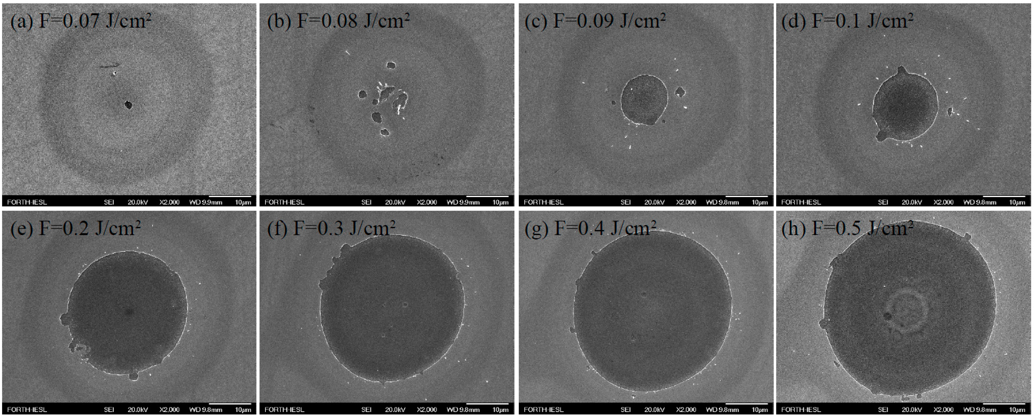
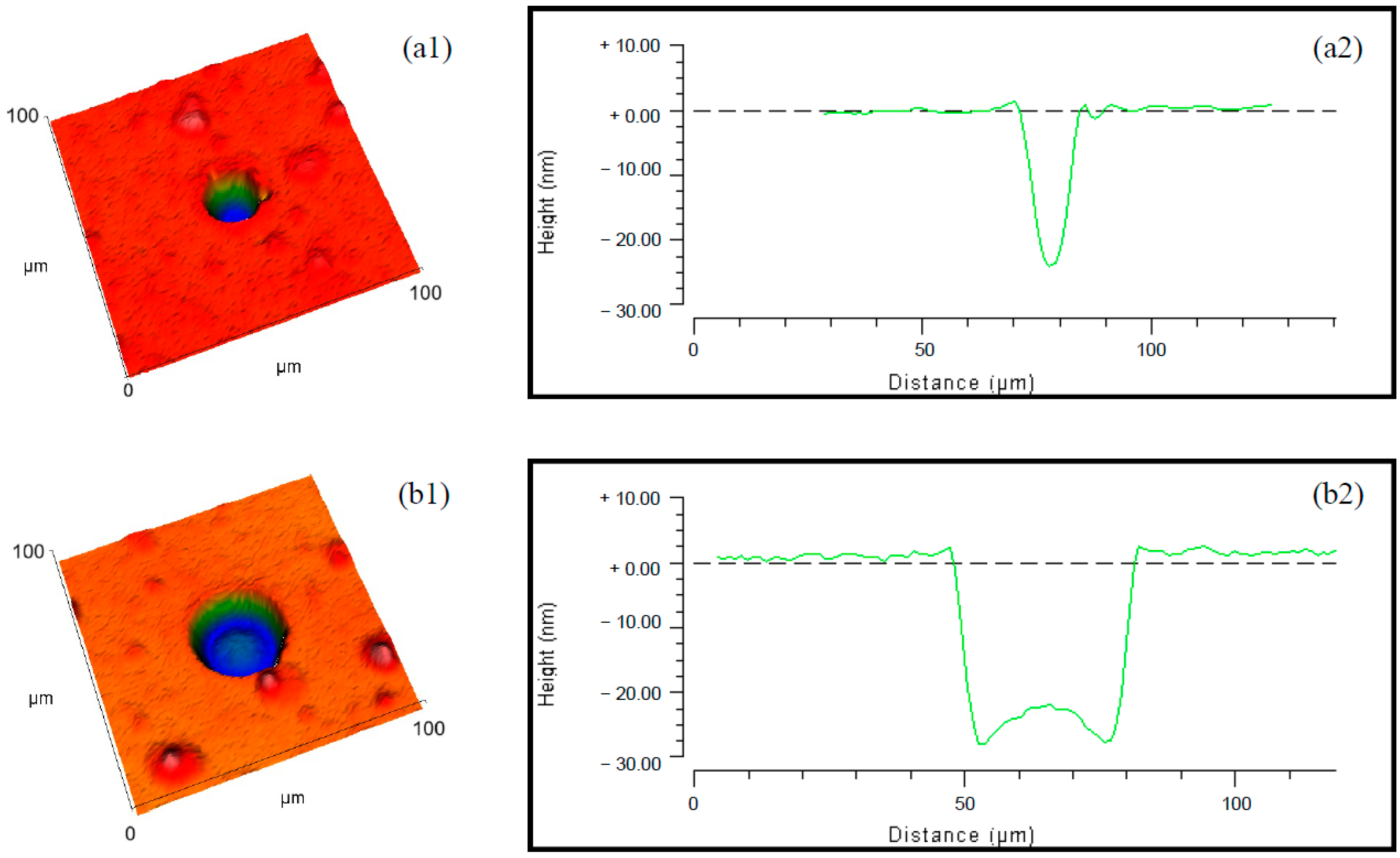
Figure 1. (a) A scheme of an NLTF cross-section and laser beam action direction; (b) a micrograph of the NLTF surface region after a series of single-pulse irradiations. Each circle represents a laser spot/crater produced by a single laser pulse.
Photonics 11 01054 g001
Figure 2. SEM micrographs of representative spots/craters (ah) taken from 10 × (Ni/Ti) surface after irradiations with single 170 fs laser pulses (same magnification ×2000). The laser fluence is written on each of them.
Photonics 11 01054 g002
Figure 3. Profilometry analyses of 10 × (Ni/Ti) surface: (a1,b1) 3D presentations and (a2,b2) 2D profiles of the modified areas produced with 0.1 J/cm2 and 0.2 J/cm2 laser fluence, respectively.
Photonics 11 01054 g003
Figure 4. SEM micrographs of the LIPSSs evolution after two to fifty successive pulses irradiation at fluence of 0.1 J/cm2 (magnification 5000× for (ac) and 2000× for (df)).
Photonics 11 01054 g004
Figure 5. (ad) Details taken from the same spots/craters presented on Figure 4 after N = 2, 3, 5 and 10 pulses. Formation of HSFLs started at N = 3 pulses and was still present at N = 10 pulses (magnification is ×15,000 in the micrographs).
Photonics 11 01054 g005
Figure 6. Maximal depths of the craters after multi-pulse irradiation of NLTF measured by profilometry.
Photonics 11 01054 g006
Figure 7. Lattice temperature field evolution in depth (in the center of the Gaussian spot), perpendicular to the surface of the sample after one pulse at F = 0.2 J/cm2.
Photonics 11 01054 g007
Table 1. Values of depth after single USLP irradiation areas, measured by profilometry.
Pulse Fluence
[J/cm2]
Single-Step Ablation
Minimal/Maximal Depth of the [nm]
0.0921.0
0.121.0
0.222.0/26.6
0.321.2/27.6
0.422.7/27.9
Pulse fluence
[J/cm2]
Two-step ablation
depths [nm]
0.5first step 23.2
second step 41.3
1.0>440 *
* For 0.6 J/cm2 and higher values fluence, measurement was uncertain because of expelled material above the surface. The surface parameter determination accuracy is <4.5%.
Disclaimer/Publisher’s Note: The statements, opinions and data contained in all publications are solely those of the individual author(s) and contributor(s) and not of MDPI and/or the editor(s). MDPI and/or the editor(s) disclaim responsibility for any injury to people or property resulting from any ideas, methods, instructions or products referred to in the content.

