Article

Absorber-Free Mode-Locking of a Hybrid Integrated Diode Laser at Sub-GHz Repetition Rate †

1
Laser Physics and Nonlinear Optics, Mesa+ Institute for Nanotechnology, Department for Science and Technology, Applied Nanophotonics, University of Twente, 7522 NB Enschede, The Netherlands
2
Chilas B.V., 7521 AN Enschede, The Netherlands
*
Author to whom correspondence should be addressed.
This work is an extension of our previous conference paper titled “Using hybrid integrated InP-Si3N4 diode lasers for the generation of sub-GHz repetition rate frequency combs”. In Proceedings of the SPIE Photonics West in 2022, San Francisco, CA, USA, 22–27 January 2022. The paper can be accessed via DOI: https://doi.org/10.1117/12.2661210.
Photonics 2024, 11(11), 1002; https://doi.org/10.3390/photonics11111002
Submission received: 16 September 2024 / Revised: 8 October 2024 / Accepted: 21 October 2024 / Published: 24 October 2024
(This article belongs to the Section Lasers, Light Sources and Sensors)

Abstract

We demonstrate absorber-free passive and hybrid mode-locking at sub-GHz repetition rates, using a hybrid integrated extended cavity diode laser operating near 1550 nm. The laser is based on InP as a gain medium and a Si3N4 waveguide feedback circuit. Absorber-free Fourier domain mode-locking with ≈15 comb lines at around 0.2 mW total power is achieved with repetition rates around 500 MHz, using three highly frequency-selective micro-ring resonators that extend the on-chip cavity length to 0.6 m. To stabilize the repetition rate, hybrid mode-locking is demonstrated by weak RF modulation of the diode current. The RF injection reduces the Lorentzian linewidth component from 8.9 kHz to a detection-limited value of around 300 mHz. To measure the locking range of the repetition rate, the injected RF frequency is tuned with regard to the passive mode-locking frequency and the injected RF power is varied. The locking range increases approximately as a square-root function of the injected RF power. At 1 mW injection, a wide locking range of about 80 MHz is obtained. We also observe the laser maintaining stable mode-locking when the DC diode pump current is increased from 40 mA to 190 mA, provided that the cavity length is maintained constant with thermo-refractive tuning.

1. Introduction

Mode-locked lasers, also called comb lasers [1] or laser frequency combs [2], have gained considerable interest, such as in frequency metrology [3], applied spectroscopy [4], or ranging [5]. Of particular interest are dense frequency combs, i.e., with small mode spacing through low, sub-GHz, repetition rates, for instance, to resolve the typically GHz-wide absorption lines of atmospheric trace gases [6] or to extract thermodynamic properties (temperature, density, and pressure) of molecular gas samples from pressure broadening and line shifting [7]. Other applications lie in microwave photonics, where optical comb lines can be used as a local oscillator, enabling data to be upconverted or downconverted across different RF bands by switching the carrier frequency [8]. Further potential applications of low repetition rate frequency combs could be enabled by miniaturization through photonic integration with electrically pumped semiconductor optical amplifiers. Examples are the upscaling of quantum optical systems [9,10,11,12] or compact LIDAR sensors [13]. In all instances, maintaining a high level of frequency stability is essential.
Conventionally, providing low sub-GHz repetition rates has been based on bulk lasers with long (meter-sized) resonators, typically Ti:Sapphire lasers and rare-earth-doped fiber lasers. A central property of such gain media that enables stable mode-locking in the form of pulses is that the gain lifetime is much longer than the cavity roundtrip time (tens to hundreds of microseconds as compared to typically around ten nanoseconds, respectively). Nevertheless, such lasers exhibit complexity in operation due to the need for optical pumping, while physically long bulk cavities make these systems susceptible to mechanical and acoustic perturbations. These features, including size and weight, limit bulk lasers predominately to lab usage.
To address the named drawbacks, there has been a push to develop frequency combs based on integrated photonics, which offers compact, chip-based solutions that can be scaled toward more complex systems. An example is generating Kerr-combs in micro-ring resonators [14,15]. These combs can provide extremely wide spectra; however, the repetition rates are high, typically above 50 GHz and the conversion efficiency is typically only at the percent level [16]. Monolithic mode-locked diode lasers provide the unique advantage of direct electrical pumping, eliminating the need for optical pumping and thus providing higher optical power and overall efficiencies [17]. Electrical pumping and monolithic integration of the laser cavity strongly decreases the susceptibility to acoustic perturbations and simplifies the overall system, including thermal management. However, monolithic mode-locked diode lasers share a drawback with Kerr frequency combs in that they also exhibit high GHz repetition rates due to their short cavity length. A fundamental limitation of monolithic diode lasers is the broader intrinsic linewidth of the comb frequencies [18,19], which is due to the short cavity length as well, in combination with a relatively higher intrinsic waveguide loss in diode laser amplifiers.
An interesting solution for lowering the repetition rate and the intrinsic linewidth of diode lasers is to increase the cavity length by heterogeneous integration [1] and hybrid integration [20]. These techniques involve the use of extended cavities such as that made of low-loss Si3N4 feedback circuits and integrated saturable absorbers to generate mode-locked pulses. Although such feedback circuits can provide long roundtrip lengths in a chip-size format, there is a fundamental stability problem. Lowering the repetition rates to the sub-GHz range is prone to chaotic fluctuations [21,22] or harmonic mode-locking [23] with several pulses per roundtrip and the latter increasing the repetition rate again. The reasons are the short gain lifetimes and recovery times that are typically around 1 ns in semiconductor optical amplifiers (SOA) [24]. If the roundtrip time of the pulses in the laser resonator becomes longer than the upper state lifetime, amplified spontaneous emission between pulses destabilizes mode-locking [25]. This limitation makes it difficult to achieve the desired sub-GHz repetition rates with diode lasers using extended cavities, whether using bulk optics or integrated photonics.
To open the path toward sub-GHz repetition rate mode-locking with integrated diode lasers, here we explore the alternative approach of Fourier domain mode-locking (FDML) [26]. With FDML, the laser cavity does not contain a saturable absorber such that the output is quasi-continuous. Instead, the frequency of the laser is modulated synchronously with the roundtrip time. Essentially, the output power is constant while the optical frequency is periodically chirped with the roundtrip rate, which generates a comb spectrum. FDML of a diode laser with an integrated feedback circuit has been suggested and numerically analyzed by Heck et al. in [27]. As no pulses are formed, stimulated emission continuously saturates the gain, which suppresses amplified spontaneous emissions independent of the cavity roundtrip time. We note that FDML is actually related to frequency modulation (FM) mode-locking as both can generate a quasi-continuous, periodically chirped output. However, there are some differences in their working principles and laser parameters. With FDML, the output is generated with an intracavity spectral filter, with the filter frequency periodically varied [26]. In an FM mode-locked laser, it is the cavity length that is varied via phase modulation; however, there is no spectral filter and one aims at low dispersion [28]. Our laser contains a narrowband intracavity filter with high dispersion, which is essential for self mode-locking. Another difference is that FM mode-locking can also generate short pulses, with a proper amount of dispersion and gain or loss variation [29] or via additional nonlinear effects [30]. The property of FDML being intrinsically absorber-free is also of practical relevance. For the telecom wavelength range, saturable absorbers integrated with semiconductor amplifiers are available within multi-project wafer (MPW) runs; however, other wavelength ranges require dedicated fabrication involving much higher costs. These fundamental differences and practical aspects make FDML more universal, as sub-GHz generation can presumably be obtained in many wavelength ranges due to the wide availability of semiconductor amplifiers.
In recent experiments, FDML based on diode lasers has been successfully demonstrated by using spectral feedback filtering [31,32]. We note that spectral filtering, such as with an intracavity grating, is required with standard (pulsed) mode-locking to restrict the destabilizing influence of intracavity dispersion. In contrast, to obtain stable FDML, sharper spectral filtering is required. The qualitative explanation is that the filter-induced bandwidth reduction and the associated, steep filter dispersion counteract ultrashort pulse formation and impose quasi-continuous oscillation. In more detail [33] detuned loading introduced by the filter [34] enables amplification of relaxation oscillation (RO) if the RO frequency is in resonance with the mode spacing frequency. The RO then generates multiple sidebands in the laser cavity modes, such that single-frequency oscillation is suppressed.
The lowest repetition rates reported with this approach with diode lasers so far are 255 MHz [32] and 360 MHz [31]. However, for the former, bulk optics was used for cavity length extension and spectral filtering (a lens-coupled Bragg fiber), which is not suitable for chip integration. In the other case (360 MHz), the laser was fully integrated with a SiN waveguide delay line for cavity length extension, while a Bragg waveguide served for spectral feedback filtering. The observed average repetition rate matched the extended cavity length. However, the authors also noted signs of dynamic instability due to independent locking of subgroups of modes, which we address to an insufficiently narrow Bragg filtering. In contrast, stable FDML has been observed in hybrid integrated lasers enabled by the sharper spectral filtering via micro-ring resonators [35,36]. The repetition rates of these lasers were, however, about an order of magnitude higher than in [31,32], i.e., 5 GHz and 2.5 GHz, respectively.
Here, we demonstrate stable Fourier domain mode-locking in a chip-integrated, long cavity diode laser for the first time at sub-GHz (≈500 MHz) repetition rates. The extended cavity diode laser is based on the hybrid integration of an InP semiconductor amplifier chip with a low-loss Si3N4 feedback circuit. The low repetition rate is achieved by double-passing the intracavity light through three sequential micro-ring resonators (MRRs), which extend the laser cavity roundtrip length beyond half a meter via multiple passes through the MRRs. We demonstrate tunable passive mode-locking around 500 MHz repetition rate via the laser cavity parameters. Hybrid mode-locking is achieved by driving the diode laser with an additional RF current at or around the passive repetition rate. The injected RF current stabilizes the repetition rate which is observed as a linewidth reduction in the laser’s RF spectrum. Within a locking range of up to 80 MHz, the laser’s repetition rate can be tuned with the applied RF frequency.

2. Experimental Results

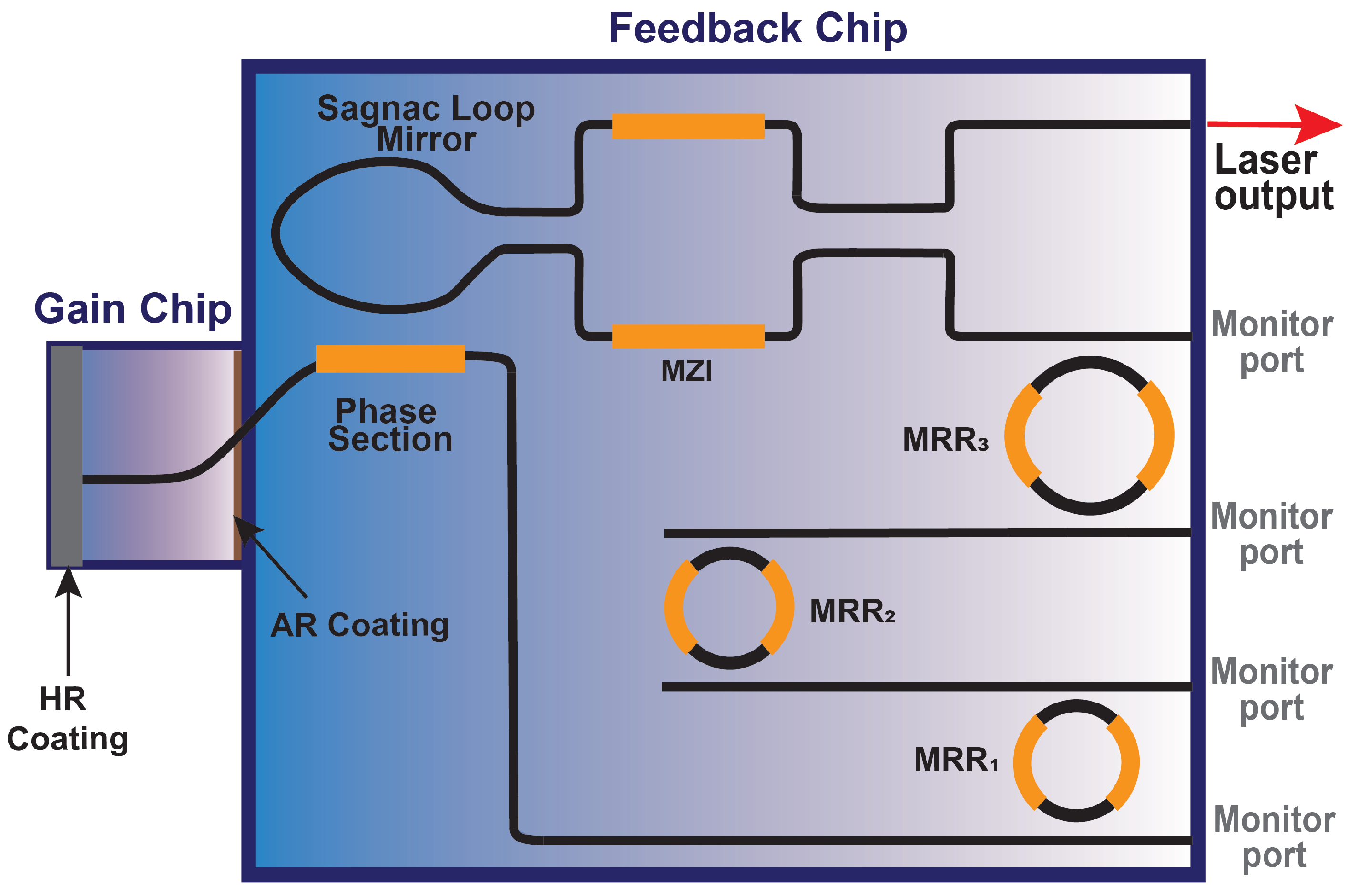
2.1. Hybrid Integrated Laser

The laser used in the experiments is shown schematically in Figure 1. The circuit design is comparable to a previous version [37] except for a somewhat longer optical cavity length of 60 cm. The laser comprises two parts. The first part is an InP gain chip, and the second part is a feedback circuit which is made of low-loss Si3N4 waveguides. The two chips are hybrid integrated by chemical bonding after edge coupling.
The InP gain chip was fabricated by the Fraunhofer Heinrich Hertz Institute (HHI, Berlin, Germany), carrying a double-pass semiconductor optical amplifier (SOA), with a 100 nm wide gain spectrum at a center wavelength around 1520 nm. The back side of the gain chip is highly-reflective (HR) coated. To minimize back-reflections into the amplifier, the front side of the gain chip is anti-reflective (AR) coated. Undesired effects from residual facet reflection are further reduced by tilting the InP waveguide at 9° relative to the facet normal. In order to optimize matching the feedback waveguide mode to that of the gain waveguide, we use tapering and a Fresnel-refraction-matched tilt of 20° [38].
Previous work on hybrid and heterogeneously integrated diode lasers has used various different arrangements of micro-ring resonators [39] to optimize certain laser output properties, such as wide wavelength coverage and mode-hop free tuning [40] or narrow intrinsic linewidth [37]. Here, to provide a low repetition rate via a long cavity length, the feedback circuit comprises a Vernier spectral filter consisting of three micro-ring resonators (MRRs) in series with different radii (R1 = 150 μm, R2 = 153 μm, and R3 = 1500 μm) and a power coupling coefficient of κ = 10%. With such coupling, the light performs approximately 1 κ κ = 9 roundtrips [41] in each MRR, when fully at resonance. Completing the laser cavity with a Sagnac waveguide mirror lets the light pass twice per roundtrip through the three MRRs. This extends the overall optical cavity roundtrip length to approximately 0.6 m when setting the MRR transmission resonances to the same wavelength via thermo-refractive tuning. The MRRs are also responsible for introducing a steep dispersion in the laser cavity, which is essential for comb generation.
An adjustable part of the intracavity light is coupled out at the Sagnac loop mirror with a tunable Mach–Zehnder interferometer (MZI). The optical length of the cavity can be fine tuned with a phase section, which tunes the cavity mode frequencies with regard to the Vernier filter transmission. For thermo-electric tuning of the MZI, the MRRs, and the phase section, the feedback chip is equipped with thin-film heaters. For stable operation, the laser is fully packaged. This includes electric wire bonding for the electrical connections, mode-matched, polarization-maintaining fibers bonded to the laser output waveguide and to the other ports and mounting chips on a Peltier cooler for temperature control.

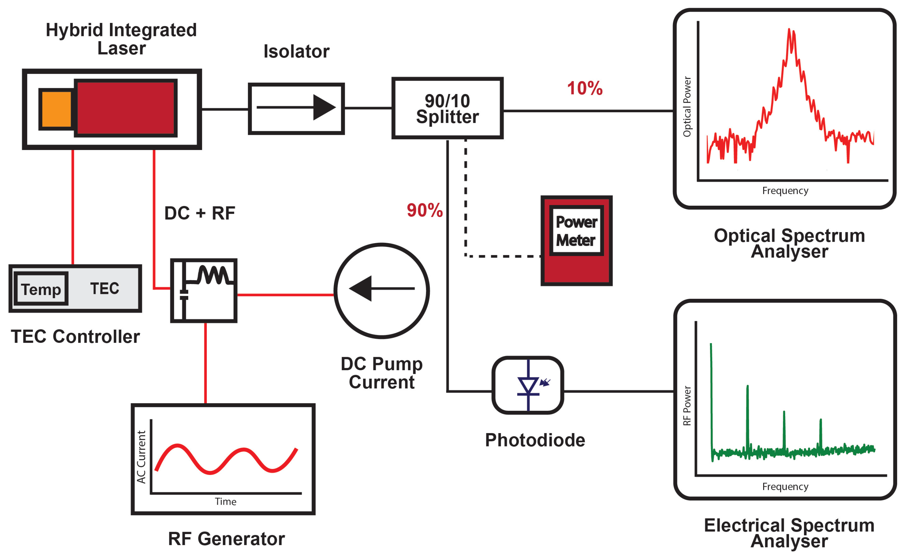
2.2. Experimental Setup

The experimental setup for mode-locking experiments is shown in Figure 2. The hybrid laser is pumped with a DC current source (ILX Lightwave, LDX-3207 Precision Current Source). For stabilizing the temperature, a temperature controller is used (ILX Lightwave, LDT-5910). The output from the laser is characterized behind an isolator (Thorlabs IO-G-1550-APC) using an optical spectrum analyzer (OSA, Coherent, Finisar WaveAnalyzer 1500S, highest resolution 150 MHz). To observe the output with higher resolution via measuring the underlying mode beating frequencies, a smaller fraction of the output light is sent via a fiber splitter (Thorlabs 1550 ± 100 nm, 90:10) to a fast photodiode (Discovery Semiconductors, 20 GHz bandwidth) connected to an electrical spectrum analyzer (ESA, Keysight, N9000B CXA) alternately to a power meter (Thorlabs, PM100D). For hybrid mode-locking, an additional AC current is applied to the gain section using an RF signal generator (Anritsu Sweep Generator, 69147A, frequency range 10 MHz–20 GHz). A bias-T (Mini-Circuits Bias-TEE, ZFBT-4R2GW, 0.1 MHz–4200 MHz) is used to add the AC current for gain modulation.

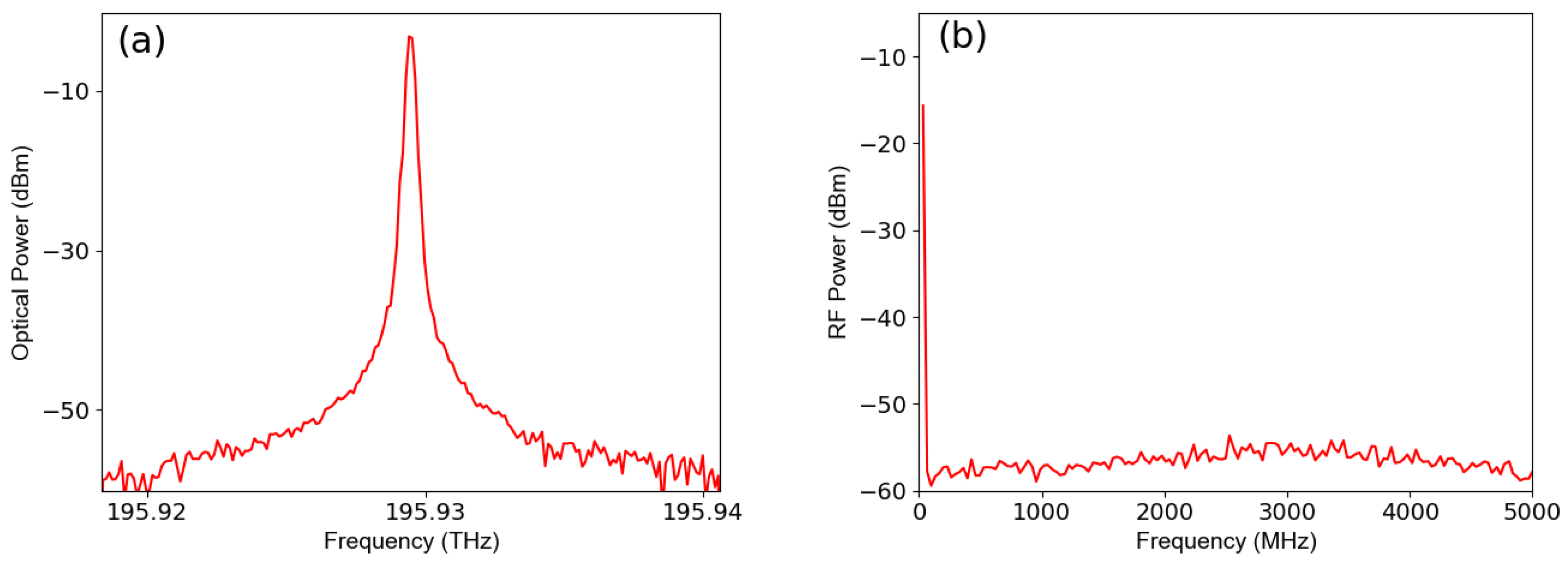
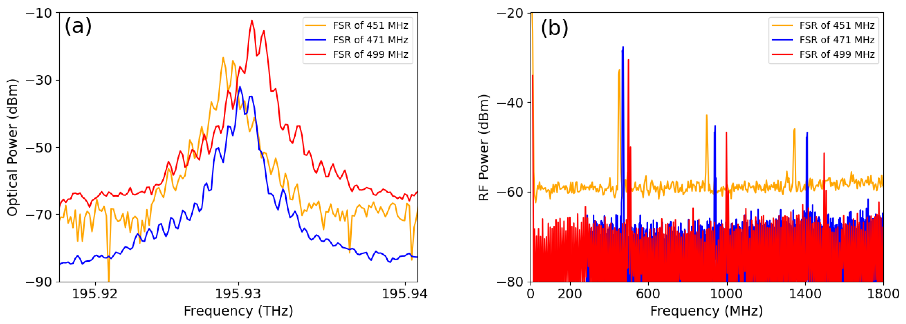
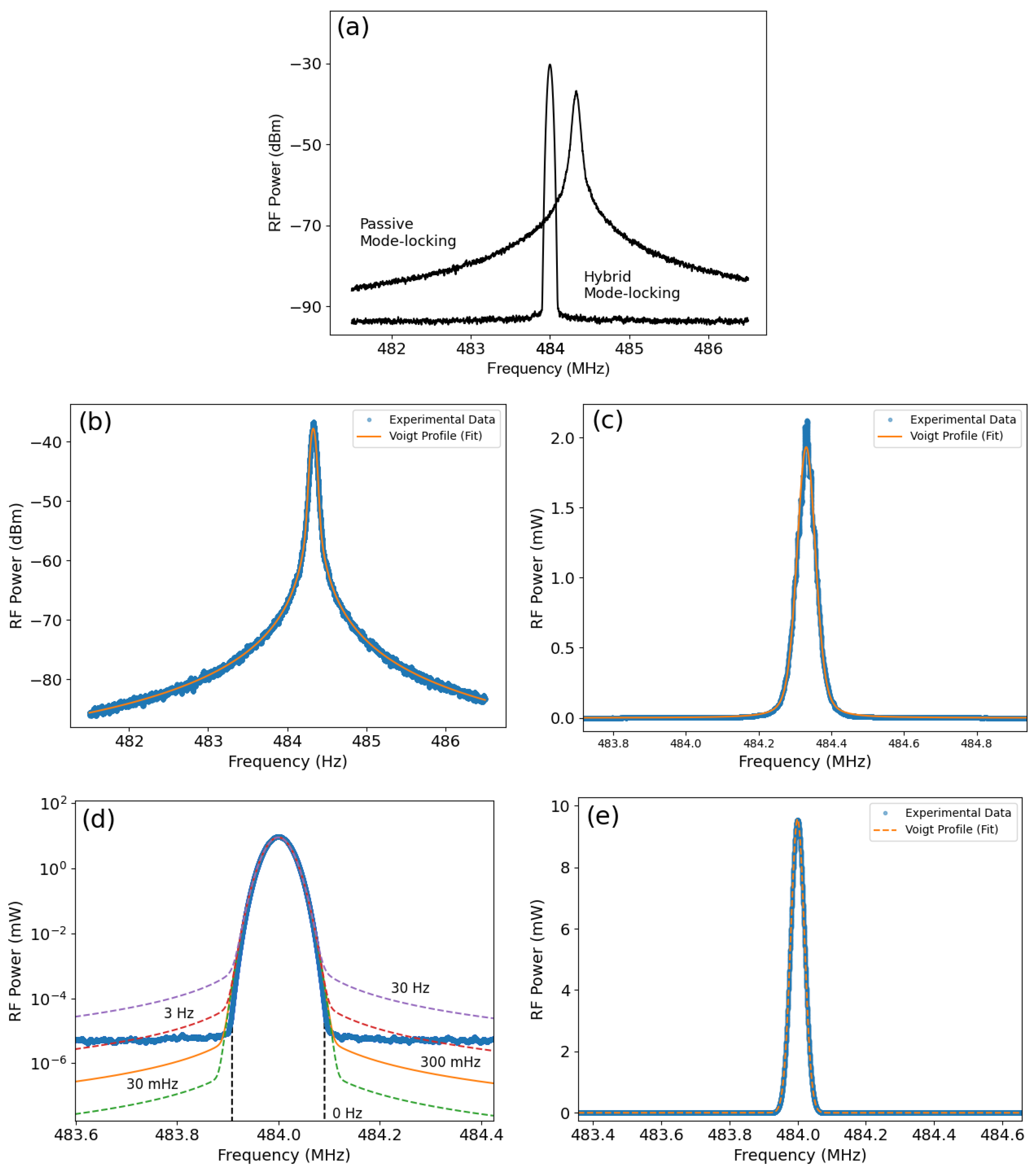
2.3. Passive Mode-Locking

In the following, we describe the sub-GHz generation of frequency combs by passive mode-locking, which is achieved by solely applying a direct current (DC) to the gain section. After turning on the pump current, the first small ring is temperature-tuned to hop the laser wavelength toward the center of the gain spectrum. The third ring is fine-tuned to maximize the output power. The threshold pump current was measured to be about 27 mA. The experiment was carried out by first tuning the laser to single-frequency oscillation, using a pump current of 50 mA, which typically generates an output power of 1 mW. Single-frequency output is obtained by tuning the laser output to near the center of the gain spectrum, using coarse adjustments of the heater currents for MRR1 and MRR2 similar to what is described in [37]. Next, the heater for MRR3 is adjusted until the laser output power is maximized simultaneously while observing a single output frequency with the OSA. The final step of preparation is tuning the phase section to maximize the power of the single-frequency output.
Figure 3a shows a typical optical power spectrum recorded with a resolution of 150 MHz, indicating single-frequency oscillation within the resolution of the OSA. The simultaneously recorded RF spectrum is displayed in Figure 3b. The spectrum is flat and close to the noise floor of the ESA. The absence of any beat notes confirms single-frequency emission.
In order to generate a frequency comb by passive mode-locking, the phase section is tuned toward a longer optical cavity length, as theoretically expected [42] via increasing the heater power. As the intermediate step toward frequency comb generation, we first observe multimode oscillation. Figure 4a presents an example of the output spectrum from the OSA when the laser operates in multiple modes. However, due to the insufficient resolution of the OSA, distinguishing multimode operation (with non-uniform frequency spacing due to intracavity dispersion) from mode-locked operation with strictly equidistant spacing is not possible. For inspecting the output with much higher resolution at the kHz level, we inspect the laser’s RF spectrum, as shown in Figure 4. The RF spectrum displays the presence and spacings of multiple optical frequencies via their RF beating frequencies. It can be seen that the RF spectrum comprises a larger variety of beat frequencies with different spacings. We address this to the presence of chaotic dynamics as described in [33].
To generate an optical frequency comb, we continue to increase the heater current of the phase section while monitoring the spectra at the OSA and ESA. Figure 4c shows the optical spectrum after increasing the phase section heating by 38 mW. Compared to Figure 4a, it can be seen that the number and contrast of the side peaks has increased. A clear change occurs in the RF spectrum as depicted in Figure 4d. The spectrum now consists of a set of narrowband peaks with only a single fundamental RF frequency around 451 MHz and integer multiples of it. The decay of the RF peak height is due to the smaller width of the laser power spectrum (See Figure 4c).The width of the fundamental peak lies in the kilohertz range (see next section), thus, an optical frequency comb is generated. We note that the measured repetition rate corresponds to a laser cavity roundtrip time of approximately 2.2 ns, which agrees well with the estimation of the laser’s optical roundtrip time of 0.6 m (2.0 ns). With these values, the roundtrip time is a factor of 2.2 bigger than the approximate 1 ns gain lifetime. For pulsed mode-locking using saturable absorbers, the lowest stable repetition rate would be higher, at around 1 GHz. We note that the mode-locking observed here resembles Fourier domain mode-locking, as previously observed in [33,35], though with up to an order of magnitude lower repetition rate.
For tuning of the comb line spacing such as might be required, e.g., for dual comb measurements [43], we recall that the comb spacing varies with the optical roundtrip length of the laser cavity, which should be tunable via the micro-ring resonators. A slight detuning of one of the ring resonances from each other should lower the number of MRR roundtrips performed, thereby shortening the optical cavity length, thus increasing the spacing of the comb lines.
To investigate experimentally whether such tuning is possible, we used detunings of the MRRs followed by optimizing the phase section as described above. Typically, one of the small MRRs is slightly detuned causing multimode operation before the phase section is tuned to restore mode-locking. As an example, to obtain mode-locking starting from single-frequency oscillation (MRR1 tuned to 43.87 mW, MRR2 to 151.25 mW, MRR3 to 126.57 mW, and phase section tuned to 101.94 mW), the heater settings were modified to obtain mode-locking with three different repetition rates (see Figure 5, which includes the heater settings for each repetition rate). Figure 5 shows that the optical spectra remain similar (due to limited resolution) while the RF spectra reveal mode-locking at various repetition rates: 451 MHz, 471 MHz, and 496 MHz (selected as three typical cases with repetition rates less than 500 MHz). Also, repetition rates higher than 500 MHz up to 650 MHz, were obtained with further detuning of the ring resonators, though higher repetition rates are not subject to investigation here.

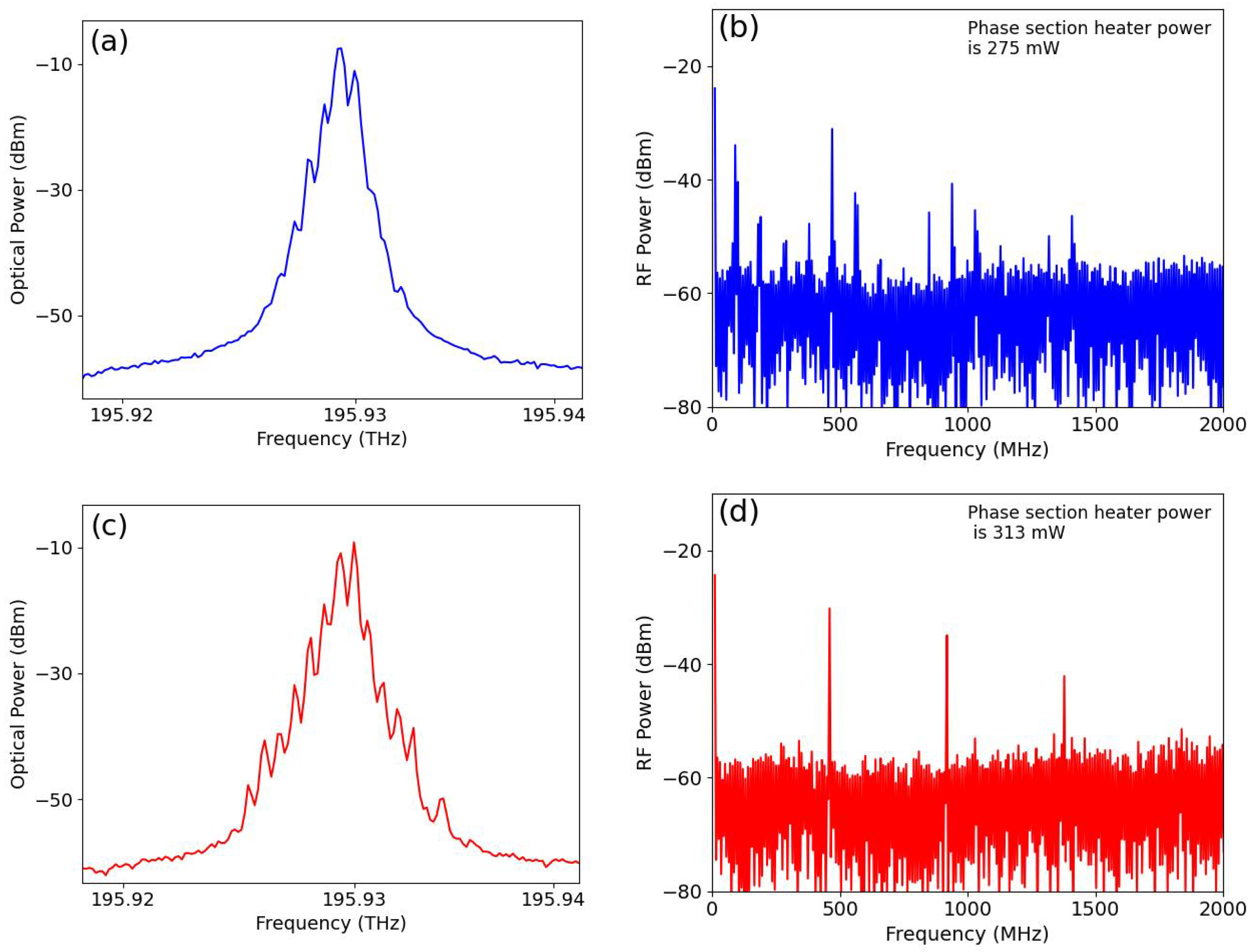
2.4. Hybrid Mode-Locking

Passive, absorber-free mode-locking, as described in Section 2.3, is a simple and robust method because it does not require any additional components such as electro-optic or acousto-optic modulators. However, passive mode-locking bears the drawback of the repetition rate being subject to drift and jitter. Jitter is caused by intrinsic effects such as spontaneous emission in the laser modes in combination with gain-index coupling in the semiconductor optical amplifier. Also, external effects lead to instabilities such as acoustic perturbations and temperature drift that change the cavity length on various time scales. For instance, in our experiments, we observe a thermal drift of the repetition rate in the order of 20 MHz/min, which is consistent with the remaining temperature instability displayed by the LDT-5910 thermal controller. To increase the stability of the repetition rate, we take a well-known hybrid mode-locking approach, where passive mode-locking is supported and stabilized with an external RF oscillator. If the frequency of the oscillator is chosen close enough to the passive repetition rate, within the so-called locking range, the optical roundtrip rate assumes the externally applied frequency [44,45].
For hybrid mode-locking, we add a sinusoidal modulation to the laser pump current using a frequency tunable RF generator (see setup Figure 2). Initially, we applied a fixed modulation power of 1 mW (corresponding to 0.7 mA) and a DC pump current of 50 mA (as used in measurements for Figure 3, Figure 4 and Figure 5). First, the laser was set to passive mode-locking at 484.3 MHz with the RF oscillator turned off. Then, the RF frequency was set to a similar value (484 MHz), and the RF current was applied while monitoring the laser’s RF spectrum. Figure 6 displays the RF spectra measured with passive and hybrid mode-locking. Their comparison shows that passive mode-locking entails a broad peak with wide line wings, whereas RF injection yields a stabilization of the repetition rate seen as reducing the wings to a level at or below the experimental noise floor.
To quantify the linewidth reduction, we performed a Voigt fit analysis [46], with the results summarized in Figure 6b–e. For the case of passive mode-locking, we fitted a logarithmic Voigt profile (relative RF power in dB) to the measured RF spectrum, see Figure 6b. The RMS (root-mean-square) fit shows excellent agreement, yielding a Gaussian linewidth (21.4 kHz) comparable to the resolution and a Lorentzian width of 8.9 kHz. Fitting a Voigt profile to the same data, now on a linear vertical scale (Figure 6c), delivers somewhat different linewidth values, 27.6 kHz and 4.8 kHz, respectively. The reason for these differences is that the logarithmic fit is more precise for the Lorentzian linewing component, where most of the experimental data are located. The linear fit is more precise for the Gaussian component because it minimizes deviations of the highest-power values, which are found near line center. The deviations between the respective Gaussian and Lorentzian components show that the linewidth is not a pure Voigt profile.
For the case of hybrid mode-locking, a logarithmic RMS Voigt fit did not provide reliable linewidth values because the Lorentzian linewings were at or below the experimental noise floor. To determine an upper limit for the Lorentzian part, Figure 6d shows the measured RF spectrum with a series of logarithmic Voigt profiles. These have a fixed Gaussian width (19.9 kHz obtained with a linear Voigt fit) and a stepwise increased Lorentzian width. The Gaussian width is likely due to the used RF oscillator, as we found the same shape and width with a characterization of its noise spectrum. It can be seen that if the Lorentzian linewidth exceeds an upper limit of around 300 mHz, the Lorentzian wings rise above the noise level, which is inconsistent with the experimental data. Summarizing, we observed that mode-locking reduced the Lorentzian linewidth by at least three orders of magnitude, down to a detection-limited upper value of 300 mHz. Further investigation might also include single-sideband phase noise measurements to reveal more details on the lineshape.

2.5. Locking Range

In this section, we present a measurement of the locking range, which is important for the long-term stability of the repetition rate. If the locking range is bigger than the interval within which the passive repetition rate drifts, hybrid mode-locking might be maintained indefinitely, in spite of cavity drift. With passive mode-locking, we observed that the repetition rates typically drift within an interval smaller than 50 MHz with a speed below 20 MHz/min.
The experiments are carried out by incrementing the external modulation frequency across the passive repetition rate while recording RF spectra. First, we measured the size of the locking range with a fixed RF modulation power of 1 mW. Figure 7 presents examples of recorded RF spectra plotted with a vertical offset (left-hand side vertical scale) equal to the frequency selected at the RF oscillator. The right-hand side scale shows the RF power of the laser spectra. Before applying RF modulation, the repetition rate of passive mode-locking was set to a value of around 484 MHz. For the lowest applied frequency of 420 MHz (blue trace at the bottom), the spectrum shows a modulation peak at 420 MHz. The second, larger, fixed-frequency peak at 484 MHz indicates that the passive mode-locking is still present. When tuning the external oscillator closer to the fixed-frequency peak, at approximately 38 MHz distance (i.e., with the external modulation set to 458 MHz, second trace from bottom), the passive mode-locking peak vanishes, leaving only a single RF peak in the spectrum. This proves that the external frequency has entered the locking range causing hybrid mode-locking at the frequency of the external oscillator. When tuning the external frequency right onto the passive mode-locking frequency (modulation frequency 490 MHz, third trace from bottom), hybrid mode-locking remains still distinguishable from passive mode-locking via strong linewidth narrowing, as in Figure 6. At about 545 MHz, the passive mode-locking peak re-appears (near 500 MHz), in addition to RF modulation (uppermost trace). The frequency of hybrid mode-locking follows the modulation frequency, as can be seen from the linear fit line that follows well the position of the tunable peaks. In these experiments, we find an RF locking range with a full width of approximately 82 MHz.
A second, well-known signature of injection locking is that the locking range should vary with the injected power following a square-root dependence [44]. Specifically with diode lasers, the locking range is expected to increase asymmetrically with injected power, which is due to gain-index coupling in semiconductor amplifiers [45].
To verify the presence of these properties and for a more quantitative characterization, we measured the width of the locking range as a function of the applied RF power. In the experiments, after establishing passive locking at around 492 MHz, the RF power was increased in steps from −10 dBm (0.1 mW) to 1 dBm (1.2 mW), and the edges of the locking range were determined, as described in Figure 7 (disappearance and reappearance of the passive repetition rate, observable with a typical experimental error of a few MHz). The results are summarized in Figure 8. The horizontal black dashed line indicates the frequency of passive mode-locking. It can be seen that the lower edge of the locking range decreases in frequency (45 MHz) while the upper edge increases in value (54 MHz). It can also be seen that the edges of the locking range vary asymmetrically, following approximately two square-root fit functions plotted for comparison. For hybrid mode-locking of diode lasers with semiconductor saturable absorbers, it has been shown [44] that the gain-index coupling parameter (Henry’s linewidth enhancement factor) of both the gain section and the saturable absorber contribute to an asymmetric RF locking range. In our experiments, no saturable absorber is present, and the observed asymmetry can thus be addressed solely to gain-index coupling in the semiconductor amplifier.

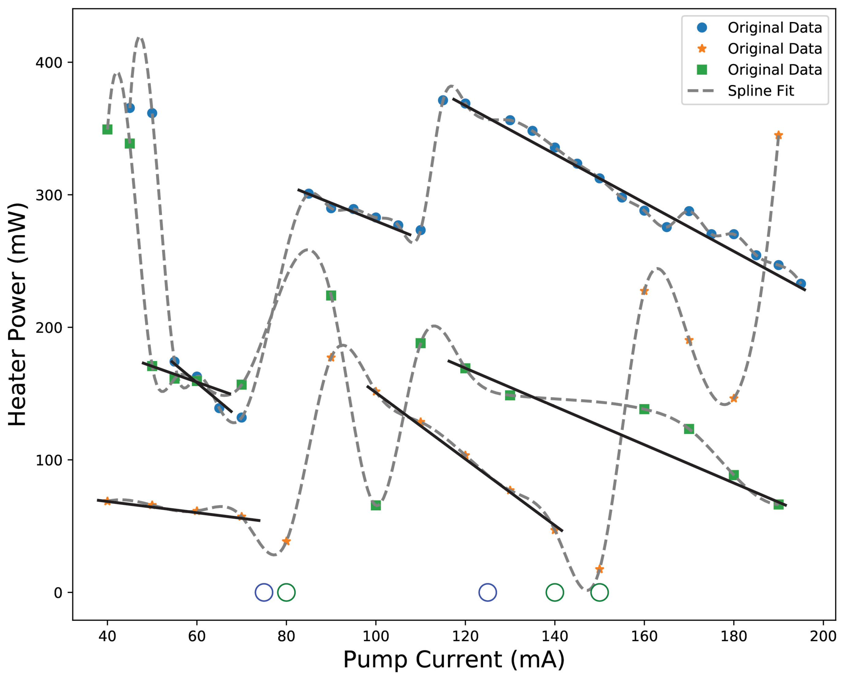
2.6. Relation Between Pump Current and Heater Settings

The experiments described so far used a fixed DC pump current of 50 mA, which is moderately above the threshold current (27 mA). Theoretical modeling has predicted a high robustness of the observed Fourier domain mode-locking upon increasing the pump current [42]. For a laser of similar design, though with about ten-times higher repetition rate, it was predicted that, beyond about five-times the threshold, mode-locking is maintained with a constant setting of the phase section when further increasing the pump current. This prediction is, however, based on a simplified description that neglects spatial gain variations or thermally induced phase shifts in the gain section, which might terminate mode-locking when increasing the pump current.
To examine these predictions, we investigate whether mode-locking can be maintained toward increasing pump current, which is also of interest for providing frequency combs with increased output power. The experiment was carried out as follows. First, stable mode-locking was established as described in Section 2.3; then, the pump current was increased in steps. With each increase, we observed that the mode-locking became either unstable or terminated, which is different than predicted [33]. However, the mode-locking became re-established by re-adjusting the phase section heater current, generally to some lower value. Figure 9 shows the measured heater power required to re-establish mode-locking vs. step-wise increasing the diode laser pump current from 50 mA to 190 mA. The figure presents three different datasets, obtained with three independent measurement runs with the same settings spanning approximately the same range of pump currents. Straight lines with an average slope of −1.7 mW/mA were drawn if more than two data points lie in proximity before any steep dip or rise is seen in a measurement run. The data show that the heater current follows an approximately linear relation for most of the data points.
Our interpretation of the observed linear variation is that increasing the diode pump current does not only increase the gain and output of the laser, but it also increases the temperature of the InP p-n junction, roughly in proportion with the current. Via the thermo-optic coefficient of the semiconductor material, this increases the laser cavity roundtrip phase. To maintain mode-locking, the increased phase needs to be compensated by reducing the phase shift in the Si3N4 phase section. We note that the phase shift is approximately proportional to the electric power, i.e., to the square of the heater current. We find that the negative sign of the slope in Figure 9 and its value are in reasonable agreement with typically expected temperature changes that are on the order of 20 deg in the InP p-n junction [47] and in the order of 200 deg in the Si3N4 phase section [48]. For this, we have considered the ratio of the respective thermo-optic coefficients [49,50] and the lengths of the gain section (700 µm) and the phase section (1 mm).

3. Summary and Conclusions

Using a hybrid integrated diode laser, we demonstrate absorber-free passive mode-locking at sub-GHz repetition rates as low as 451 MHz. The laser comprises an InP-based semiconductor optical amplifier and a Si3N4 feedback circuit. A low repetition rate is provided via a long effective laser cavity, obtained via a feedback circuit with three double-passed micro-ring resonators as a spectral Vernier filter. Passive mode-locking is achieved by slightly increasing the cavity length via an integrated phase section when the laser is initially in single-frequency operation. The repetition rate of the laser is tunable across a wide range from about 450 to 650 MHz. This is achieved by tuning the micro-ring resonators slightly off mutual resonance, as this reduces the number of roundtrips and thereby shortens the effective laser cavity length. To stabilize the repetition rate of the laser, we add an RF current to the DC diode pump current, which induced hybrid mode-locking at the external RF frequency. The corresponding stabilization of the repetition rate causes a reduction in the Lorentzian linewidth component from 8.9 kHz to a detection-limited value around 300 mHz. As a comparison, our Lorentzian component fits well with an RMS linewidth measurement in [51]. However, our Gaussian linewidth component is much bigger, which we address to our RF oscillator showing broader Gaussian noise. We measure a locking range of about 80 MHz with 1 mW RF power. The locking range increases with the injected RF power following an asymmetric square root dependence as expected. Absorber-free, passive mode-locking was observed up to the maximum specified diode pump current by re-adjusting the cavity via the phase section. Regarding future developments, earlier numerical calculations have indicated that a further lowering of the repetition rate should be possible [52] using further length extension. Following this route promises to bring the repetition rate near that of widely used bulk lasers. As the overall bandwidth of the combs demonstrated here is still relatively narrow, further broadening should be considered. Options could be four-wave mixing, a subsequent InP amplifier chip, or a stitching (locking) together of several comb lasers with adjacent spectral coverage.

Author Contributions

Following are the author contributions to this study. Conceptualization, K.-J.B. and A.M.; methodology, A.M. and K.-J.B.; software, A.M. and A.v.R.; formal analysis, A.M.; investigation, A.M.; resources, Y.F., J.M., A.v.R., A.M., P.J.M.v.d.S. and H.M.J.B.; data curation, A.M.; writing—original draft preparation, A.M. and K.-J.B.; writing—review and editing, A.M., K.-J.B. and P.J.M.v.d.S.; visualization, A.M. and K.-J.B.; supervision, K.-J.B., P.J.M.v.d.S. and H.M.J.B.; project administration, K.-J.B. and A.M.; funding acquisition, K.-J.B. All authors have read and agreed to the published version of the manuscript.

Funding

This project is partly funded by The Netherlands Organisation for Scientific Research (NWO) under the project 16718, title: “Ultra-narrowband lasers on a chip” and partly by the European Union’s Horizon 2020 research and innovation program under grant agreement No. 780502 (3PEAT).

Institutional Review Board Statement

Not applicable.

Informed Consent Statement

Not applicable.

Data Availability Statement

The data presented in this study are available from the authors upon request.

Acknowledgments

The authors gratefully acknowledge Yvan Klaver, Lisa Winkler, and Redlef Braamhaar for fruitful discussions on mode-locking and vital technical support throughout this work.

Conflicts of Interest

The authors declare no conflicts of interest.

References

  1. Cuyvers, S.; Haq, B.; Op de Beeck, C.; Poelman, S.; Hermans, A.; Wang, Z.; Gocalinska, A.; Pelucchi, E.; Corbett, B.; Roelkens, G.; et al. Low Noise Heterogeneous III-V-on-Silicon-Nitride Mode-Locked Comb Laser. Laser Photonics Rev. 2021, 15, 2000485. [Google Scholar] [CrossRef]
  2. Uvin, S.; Keyvaninia, S.; Lelarge, F.; Duan, G.H.; Kuyken, B.; Roelkens, G. Narrow line width frequency comb source based on an injection-locked III-V-on-silicon mode-locked laser. Opt. Express 2016, 24, 5277. [Google Scholar] [CrossRef]
  3. Diddams, S.; Vahala, K.-J.; Udem, T. Optical frequency combs: Coherently uniting the electromagnetic spectrum. Science 2020, 369, eaay3676. [Google Scholar] [CrossRef]
  4. Kranendonk, L.A.; An, X.; Caswell, A.W.; Herold, R.E.; Sanders, S.T.; Huber, R.; Fujimoto, J.G.; Okura, Y.; Urata, Y. High speed engine gas thermometry by Fourier-domain mode-locked laser absorption spectroscopy. Opt. Express 2007, 15, 15115. [Google Scholar] [CrossRef]
  5. Trocha, P.; Kemal, J.N.; Gaimard, Q.; Guy, A.; François, L.; Abderrahim, R.; Wolfgang, F.; Sebastian, R.; Christian, K. Ultra-fast optical ranging using quantum-dash mode-locked laser diodes. Sci. Rep. 2022, 12, 1076. [Google Scholar] [CrossRef] [PubMed]
  6. Coburn, S.; Alden, C.B.; Wright, R.; Cossel, K.; Baumann, E.; Truong, G.-W.; Giorgetta, F.; Sweeney, C.; Newbury, N.R.; Prasad, K.; et al. Regional trace-gas source attribution using a field-deployed dual frequency comb spectrometer. Optica 2018, 5, 320. [Google Scholar] [CrossRef]
  7. Swann, W.C.; Gilbert, S.L. Pressure-induced shift and broadening of 1510–1540-nm acetylene wavelength calibration lines. J. Opt. Soc. Am. B 2000, 17, 1263. [Google Scholar] [CrossRef]
  8. Lei, L.; Zhang, J.; Zhou, J.; Gao, G.; Xue, M.; Zhang, X. Study on all-optical cross-band frequency conversion for communication satellite. In Proceedings of the 2017 IEEE 17th International Conference on Communication Technology (ICCT), Chengdu, China, 27–30 October 2017; Volume 5, p. 1079. [Google Scholar]
  9. Reimer, C.; Caspani, L.; Clerici, M.; Ferrera, M.; Kues, M.; Peccianti, M.; Pasquazi, A.; Razzari, L.; Little, B.E.; Chu, S.T.; et al. Integrated frequency comb source of heralded single photons. Opt. Express 2014, 22, 6535. [Google Scholar] [CrossRef]
  10. Nicholas, H.; Bunandar, D.; Pant, M.; Steinbrecher, G.; Mower, J.; Mihika, P.; Baehr-Jones, T.; Hochberg, M.; Englund, D. Large-scale quantum photonic circuits in silicon. Nanophotonics 2016, 5, 456. [Google Scholar]
  11. Taballione, C.; Anguita, M.; Goede, M.; Venderbosch, P.; Kassenberg, B.; Snijders, H.; Kannan, N.; Vleeshouwers, W.; Smith, D.; Epping, J.; et al. Large-scale quantum photonic circuits in silicon. Quantum 2023, 7, 1071. [Google Scholar] [CrossRef]
  12. Mahmudlu, H.; Robert, J.; Rees, A.; Kashi, A.H.; Epping, J.; Haldar, R.; Boller, K.-J.; Kues, M. Fully on-chip photonic turnkey quantum source for entangled qubit/qudit state generation. Nat. Photonics 2023, 17, 518. [Google Scholar] [CrossRef]
  13. Swann, W.; Newbury, N.R. Frequency-resolved coherent lidar using a femtosecond fiber laser. Opt. Lett. 2006, 31, 826. [Google Scholar] [CrossRef] [PubMed]
  14. Pascal, D.; Schliesser, A.; Arcizet, O.; Wilken, T.; Holzwarth, R.; Kippenberg, T. Optical Frequency Comb Generation from a Monolithic Microresonator. Nature 2008, 450, 1214. [Google Scholar]
  15. Stern, B.; Ji, X.; Okawachi, Y.; Gaeta, A.L.; Lipson, M. Battery-operated integrated frequency comb generator. Nature 2018, 562, 401. [Google Scholar] [CrossRef]
  16. Wang, P.-H.; Jaramillo-Villegas, J.A.; Xuan, X.; Xue, X.; Bao, C.; Leaird, D.E.; Qi, M.; Weiner, A.M. Intracavity characterization of micro-comb generation in the single-soliton regime. Opt. Express 2016, 24, 10890. [Google Scholar] [CrossRef]
  17. Hou, L.; Haji, M.; Marsh, J.H. Monolithic Mode-Locked Laser with an Integrated Optical Amplifier for Low-Noise and High-Power Operation. IEEE J. Sel. Top. Quantum Electron. 2013, 19, 1100808. [Google Scholar] [CrossRef]
  18. Pozzi, F.; De La Rue, R.; Sorel, M. Dual-Wavelength InAlGaAs–InP Laterally Coupled Distributed Feedback Laser. IEEE Photonics Technol. Lett. 2007, 18, 2563. [Google Scholar] [CrossRef]
  19. Guzmán, R.; Gordon, C.; Orbe, L.; Carpintero, G. 1 GHz InP on-chip monolithic extended cavity colliding-pulse mode-locked laser. Opt. Lett. 2017, 42, 2318. [Google Scholar] [CrossRef]
  20. Bastiaens, H.M.J.; Neijts, G.; Memon, A.; Fan, Y.; Mak, J.; Geskus, D.; Hoekman, M.; Moskalenko, V.; Bente, E.A.J.M.; Boller, K.-J. First demonstration of a hybrid integrated InP-Si3N4 diode laser for broadband optical frequency comb generation. Proc. SPIE 2021, 11705, 1170508. [Google Scholar]
  21. Yoon, T.H.; Jang, G.H. Period-doubling and total mode-locking, and chaotic pulsations in a GaAs ridge wave-guide external-cavity diode laser. Opt. Express 2007, 15, 14704. [Google Scholar] [CrossRef]
  22. Vladimirov, A.G.; Turaev, D. Model for passive mode locking in semiconductor lasers. Phys. Rev. A 2005, 72, 33808. [Google Scholar] [CrossRef]
  23. Zhang, Q.; Jasim, K.; Nurmikko, A.V.; Mooradian, A.; Carey, G.; Ha, W.; Ippen, E. Operation of a passively mode-locked extended-cavity surface-emitting diode laser in multi-GHz regime. IEEE Photonics Technol. Lett. 2004, 16, 885. [Google Scholar] [CrossRef]
  24. Paschotta, R. Field Guide to Laser Pulse Generation; SPIE: Bellingham, WA, USA, 2008; Volume FG14, ISBN 9780819478276. [Google Scholar]
  25. Liao, R.; Chao, M.; Youjian, S.; Demircan, A.; Steinmeyer, G. Spontaneous emission noise in mode-locked lasers and frequency combs. Phys. Rev. A 2020, 102, 013506. [Google Scholar] [CrossRef]
  26. Huber, R.; Wojtkowski, M.; Fujimoto, J.G. Fourier Domain Mode Locking (FDML): A new laser operating regime and applications for optical coherence tomography. Opt. Express 2006, 14, 3225. [Google Scholar] [CrossRef] [PubMed]
  27. Heck, M.; Bowers, J.E. Integrated Fourier-Domain Mode-Locked Lasers: Analysis of a Novel Coherent Comb Laser. IEEE J. Sel. Top. Quantum Electron. 2012, 18, 201. [Google Scholar] [CrossRef]
  28. Dong, B.; Dumont, M.; Terra, O.; Wang, H.; Netherton, A.; Bowers, J.E. Broadband quantum-dot frequency-modulated comb laser. Light Sci. Appl. 2023, 12, 182. [Google Scholar] [CrossRef]
  29. Nagar, R.; Abraham, D.; Tessler, N.; Fraenkel, A.; Eisenstein, G.; Ippen, E.P.; Koren, U.; Raybon, G. Broadband quantum-dot frequency-modulated comb laser. Opt. Lett. 1991, 16, 1750. [Google Scholar] [CrossRef]
  30. Nguyen, N.D.; Binh, L.N. Generation of high order multi-bound solitons and propagation in optical fibers. Opt. Commun. 2009, 282, 2394. [Google Scholar] [CrossRef]
  31. Ibrahimi, Y.; Boust, S.; Wilmart, Q.; Paret, J.-F.; Garreau, A.; Mekhazni, K.; Fortin, C.; Duport, F.; Dijk, F.; Sciancalepore, C.; et al. Low FSR mode-locked laser based on InP-Si3N4 hybrid integration. J. Light. Technol. 2021, 39, 7573. [Google Scholar] [CrossRef]
  32. Yuan, M.; Wang, W.; Wang, X.; Wang, Y.; Yang, Q.; Cheng, D.; Liu, Y.; Huang, L.; Zhang, M.; Liang, B.; et al. Demonstration of an external cavity semiconductor mode-locked laser. Opt. Lett. 2021, 46, 4855. [Google Scholar] [CrossRef] [PubMed]
  33. Rimoldi, C.; Columbo, L.L.; Bovington, J.; Romero-García, S.; Gioannini, M. CW Emission and Self-Pulsing in a III-V/SiN Hybrid Laser with Narrow Band Mirror. IEEE Photonics J. 2022, 14, 1540707. [Google Scholar] [CrossRef]
  34. Vahala, K.; Yariv, A. Detuned loading in coupled cavity semiconductor lasers—Effect on quantum noise and dynamics. Appl. Phys. Lett. 1984, 45, 501. [Google Scholar] [CrossRef]
  35. Mak, J.; van Rees, A.; Fan, Y.; Klein, E.J.; Geskus, D.; van der Slot, P.J.M.; Boller, K.-J. Linewidth narrowing via low-loss dielectric waveguide feedback circuits in hybrid integrated frequency comb lasers. Opt. Express 2019, 27, 13307. [Google Scholar] [CrossRef]
  36. Klaver, Y.; Epping, J.P.; Roeloffzen, C.G.H.; Marpaung, D.A.I. Self-mode-locking in a high-power hybrid silicon nitride integrated laser. Opt. Lett. 2022, 47, 198. [Google Scholar] [CrossRef] [PubMed]
  37. Fan, Y.; van Rees, A.; van der Slot, P.J.M.; Mak, J.; Oldenbeuving, R.M.; Hoekman, M.; Geskus, D.; Roeloffzen, C.G.H.; Boller, K.-J. Hybrid integrated InP-Si3N4 diode laser with a 40-Hz intrinsic linewidth. Opt. Express 2020, 28, 21713. [Google Scholar] [CrossRef]
  38. Roeloffzen, C.G.H.; Hoekman, M.; Klein, E.J.; Wevers, L.S.; Timens, R.B.; Marchenko, D.; Geskus, D.; Dekker, R.; Alippi, A.; Grootjans, R.; et al. Low-Loss Si3N4 TriPleX Optical Waveguides: Technology and Applications Overview. IEEE J. Sel. Top. Quantum Electron. 2018, 24, 4400321. [Google Scholar] [CrossRef]
  39. Tran, M.A.; Huang, D.; Guo, J.; Komljenovic, T.; Morton, P.A.; Bowers, J.E. Ring-Resonator Based Widely-Tunable Narrow-Linewidth Si/InP Integrated Lasers. IEEE J. Sel. Top. Quantum Electron. 2020, 26, 1500514. [Google Scholar] [CrossRef]
  40. van Rees, A.; Fan, Y.; Geskus, D.; Klein, E.J.; Oldenbeuving, R.M.; van der Slot, P.J.M.; Boller, K.-J. Ring resonator enhanced mode-hop-free wavelength tuning of an integrated extended-cavity laser. Opt. Express 2020, 28, 5669. [Google Scholar] [CrossRef]
  41. Liu, B.; Shakouri, A.; Bowers, J.E. Wide tunable double ring resonator coupled lasers. IEEE Photonics Technol. Lett. 2002, 14, 600. [Google Scholar]
  42. Rimoldi, C.; Columbo, L.L.; Bovington, J.; Romero-García, S.; Gioannini, M. Damping of relaxation oscillations, photon-photon resonance, and tolerance to external optical feedback of III-V/SiN hybrid lasers with a dispersive narrow band mirror. Opt. Express 2022, 30, 11090. [Google Scholar] [CrossRef] [PubMed]
  43. Coddington, I.; Swann, W.C.; Newbury, N.R. Coherent Multiheterodyne Spectroscopy Using Stabilized Optical Frequency Combs. Phys. Rev. Lett. 2008, 100, 013902. [Google Scholar] [CrossRef]
  44. Arkhipov, R.; Pimenov, A.; Radziunas, M.; Rachinskii, D.; Vladimirov, A.G.; Arsenijević, D.; Schmeckebier, H.; Bimberg, D. Hybrid Mode Locking in Semiconductor Lasers: Simulations, Analysis, and Experiments. IEEE J. Sel. Top. Quantum Electron. 2013, 19, 1100208. [Google Scholar] [CrossRef]
  45. Vladimirov, A.G.; Wolfrum, M.; Fiol, G.; Arsenijevic, D.; Bimberg, D.; Viktorov, E.; Mandel, P.; Rachinskii, D. Locking characteristics of a 40-GHz hybrid mode-locked monolithic quantum dot laser. Proc. SPIE 2010, 7720, 77200Y. [Google Scholar]
  46. Chen, M.; Meng, Z.; Wang, J.; Chen, W. Ultra-narrow linewidth measurement based on Voigt profile fitting. Opt. Express. 2015, 23, 6803. [Google Scholar] [CrossRef]
  47. Han, J.-H.; Park, S.W. Effect of temperature and injection current on characteristics of TO–CAN packaged Fabry–Perot laser diode. Curr. Appl. Phys. 2007, 7, 6. [Google Scholar] [CrossRef]
  48. Alemany, R.; Muñoz, P.; Pastor, D.; Domínguez, C. Thermo-Optic Phase Tuners Analysis and Design for Process Modules on a Silicon Nitride Platform. Photonics 2007, 8, 496. [Google Scholar] [CrossRef]
  49. Della Corte, F.G.; Cocorullo, G.; Iodice, M.; Rendina, I. Temperature dependence of the thermo-optic coefficient of InP, GaAs, and SiC from room temperature to 600 K at the wavelength of 1.5 μm. Appl. Phys. Lett. 2000, 77, 1614. [Google Scholar] [CrossRef]
  50. Arbabi, A.; Goddard, L.L. Measurements of the refractive indices and thermo-optic coefficients of Si3N4 and SiOx using microring resonances. Opt. Lett. 2013, 38, 3878. [Google Scholar] [CrossRef]
  51. Wang, Z.; Van Gasse, K.; Moskalenko, V.; Latkowski, S.; Bente, E.; Kuyken, B.; Roelkens, G.A. III-V-on-Si Ultra-dense comb laser. Light Sci. Appl. 2017, 6, e16260. [Google Scholar] [CrossRef]
  52. Mak, J. Extending Hybrid Integrated Diode Lasers to Multi-Frequency Oscillation. Ph.D. Thesis, University of Twente, Enschede, The Netherlands, 2023. [Google Scholar]
Figure 1. Schematic diagram of the hybrid integrated mode-locked laser (not to scale). The laser comprises two parts. The gain chip is highly reflective (HR) coated on the left-hand side. The other end is anti-reflective (AR) coated to reduce undesired back reflection from the interface between the two chips. Residual back reflections from the InP and Si3N4 facets are diverted out of the circuit by tilting the InP waveguide at 9° relative to the facet normal. The feedback circuit is based on Si3N4, using three micro-ring resonators (MRR1, MRR2, and MRR3) as a Vernier filter. A phase section is used to tune the frequency of the longitudinal laser cavity modes relative to the Vernier filter frequency. The feedback circuit is completed with a Sagnac loop mirror, the reflectivity of which can be controlled by a Mach–Zehnder interferometer (MZI). The MZI, MRRs, and phase section are equipped with thermoelectric heaters (shown in orange). The feedback circuit is based on asymmetric double-stripe (ADS) waveguides, fabricated by LioniX International [38]. All output ports from the chip are connected to optical fibers.
Photonics 11 01002 g001
Figure 2. Schematic view of the setup for realizing mode-locking. The figure shows the hybrid laser, to which a DC and AC current is applied, combined via a bias-T. The laser is also connected to a temperature controller. The laser output is sent via a fiber isolator and 90/10 splitter to an optical spectrum analyzer (OSA) and a power meter or to a fast photodiode followed by an electrical spectrum analyzer (ESA).
Photonics 11 01002 g002
Figure 3. (a) Optical spectrum recorded with the optical spectrum analyzer (OSA, resolution 150 MHz) when the laser is operating in a single mode. (b) The corresponding RF spectrum recorded on the electrical spectrum analyzer (ESA, resolution 3 MHz). The ESA spectrum does not display any mode-beating-related peaks, confirming single frequency operation.
Photonics 11 01002 g003
Figure 4. (a) Optica spectrum recorded on OSA when the laser is operating in multimode. (b) The corresponding RF spectrum recorded with the ESA when the laser operates in multimode. (c) Optical spectrum recorded with the OSA when the rings and phase sections are tuned and the laser is operating as a mode-locked laser. (d) The corresponding RF spectrum at the ESA when the laser operates as a mode-locked laser.
Photonics 11 01002 g004
Figure 5. (a) Optical spectrum obtained at different tunings of the MRRs and the phase section. (b) Corresponding RF spectra showing mode-locking at 451, 471, and 499 MHz. For mode-locking at 451 MHz, MRR1 is tuned to 43.87 mW, MRR2 to 151.25 mW, MRR3 to 125.76 mW, and the phase section to 138.95 mW. For 471 MHz, the tunings are 39.55 mW, 153.92 mW, 108.80 mW, and 172.15 mW, respectively. For 499 MHz, the tunings are 43.87 mW, 151.25 mW, 98.29 mW, and 176.15 mW.
Photonics 11 01002 g005
Figure 6. (a) RF spectra obtained with passive and hybrid mode-locking at repetition rates near 484 MHz. The experimental noise floor is at around −95 dB with the resolution and video bandwidth set to 47 kHz. (b) Passive mode-locking: A logarithmic Voigt fit, which gives high weight to the linewing data, yields a Lorentzian component of 4.8 kHz (Gaussian linewidth 27.6 kHz with negligible errors). (c) A Voigt fit to the same data on a linear scale puts the weight on the line-centered data and thus yields different line widths: Gaussian linewidth 21.4 kHz (Lorentzian linewidth 8.9 kHz again with negligible statistical errors). (d) Hybrid mode-locking: The black dotted line presents a pure Gaussian profile with a 19.9 kHz linewidth (obtained with a Voigt fit on a linear scale, refer (e)). The other dashed curves are Voigt profiles with a constant 19.9 kHz Gaussian component and various Lorentzian components between 30 mHz and 30 Hz. The solid orange line is a Voigt profile with a 300 mHz Lorentzian component, denoting the upper limit beyond which the line wings would rise above the noise floor, which were inconsistent with the experimental data. (e) RMS Voigt fit to the same data on a linear scale yielding a 19.9 kHz Gaussian component with near-zero Lorentzian part.
Photonics 11 01002 g006
Figure 7. RF spectra of the mode-locked laser recorded with 1 mW diode pump current modulation applied with various RF frequencies in the range between 420 and 550 MHz. The recorded spectra are offset with the applied modulation frequency (left-hand side axis). The power of the recorded laser spectra is shown at the right-hand side axis (noise levels at −90 dBm). The top and bottom spectra (blue traces) show two peaks, i.e., the laser is still passively mode-locked, as the modulation frequency lies outside the locking range. The spectra that display only a single RF peak are plotted in red. With these modulation frequencies, the laser’s passive repetition rate is locked to the frequency of the external RF oscillator (hybrid mode-locking). The green line is a linear fit connecting the positions of tunable peaks. The range within which the repetition is locked to that of the external modulation frequency is 82 MHz wide (indicated in yellow).
Photonics 11 01002 g007
Figure 8. Locking range (MHz) measured vs. injected RF power. The black dotted line in the center shows the passive mode-locking frequency at 492 MHz. The curves are two square-root fit functions with different curvature, centered at the passive mode-locking frequency.
Photonics 11 01002 g008
Figure 9. Measured heater settings of the phase section required for stable mode-locking when increasing the diode pump current. Three different datasets are shown (blue, green, and red symbols) grouped with dashed curves (spline fit), as obtained by three independent measurement runs. Open circles represent pump currents where mode-locking could not be found. It can also be seen that the absolute values for the required heater currents are not well reproducible between the different datasets (recorded on different days). We address this to experimental uncertainties, specifically to a residual thermal drift of the ring resonators. The straight lines are linear fits on subsets of data, showing an average slope of about −1.7 mW/mA.
Photonics 11 01002 g009
Disclaimer/Publisher’s Note: The statements, opinions and data contained in all publications are solely those of the individual author(s) and contributor(s) and not of MDPI and/or the editor(s). MDPI and/or the editor(s) disclaim responsibility for any injury to people or property resulting from any ideas, methods, instructions or products referred to in the content.

