1. Introduction
Surface profile measurement is essential for evaluating product characteristics and qualities such as roughness, friction, wear, and manufacturing tolerances. In recent years, various optical and non-optical methods have been applied to surface profile measurement. However, achieving picometer-level sensitivity remains challenging for these methods [
1].
Frequency Domain-Optical Coherence Tomography (FD-OCT) was proposed for biological imaging. A Fourier transform was performed on the interference spectrum to obtain cross-sectional images of samples in vivo. In recent years, FD-OCT has been widely used in surface profile measurement due to its advantages of non-contact, high speed, and good linearity [
2]. There are two general implementations of FD-OCT depending on the type of light source and detector: Spectral-Domain OCT (SD-OCT) and Swept-Source OCT (SS-OCT). In SD-OCT, a broadband light source is used, and the interference spectrum is detected with a spectrometer [
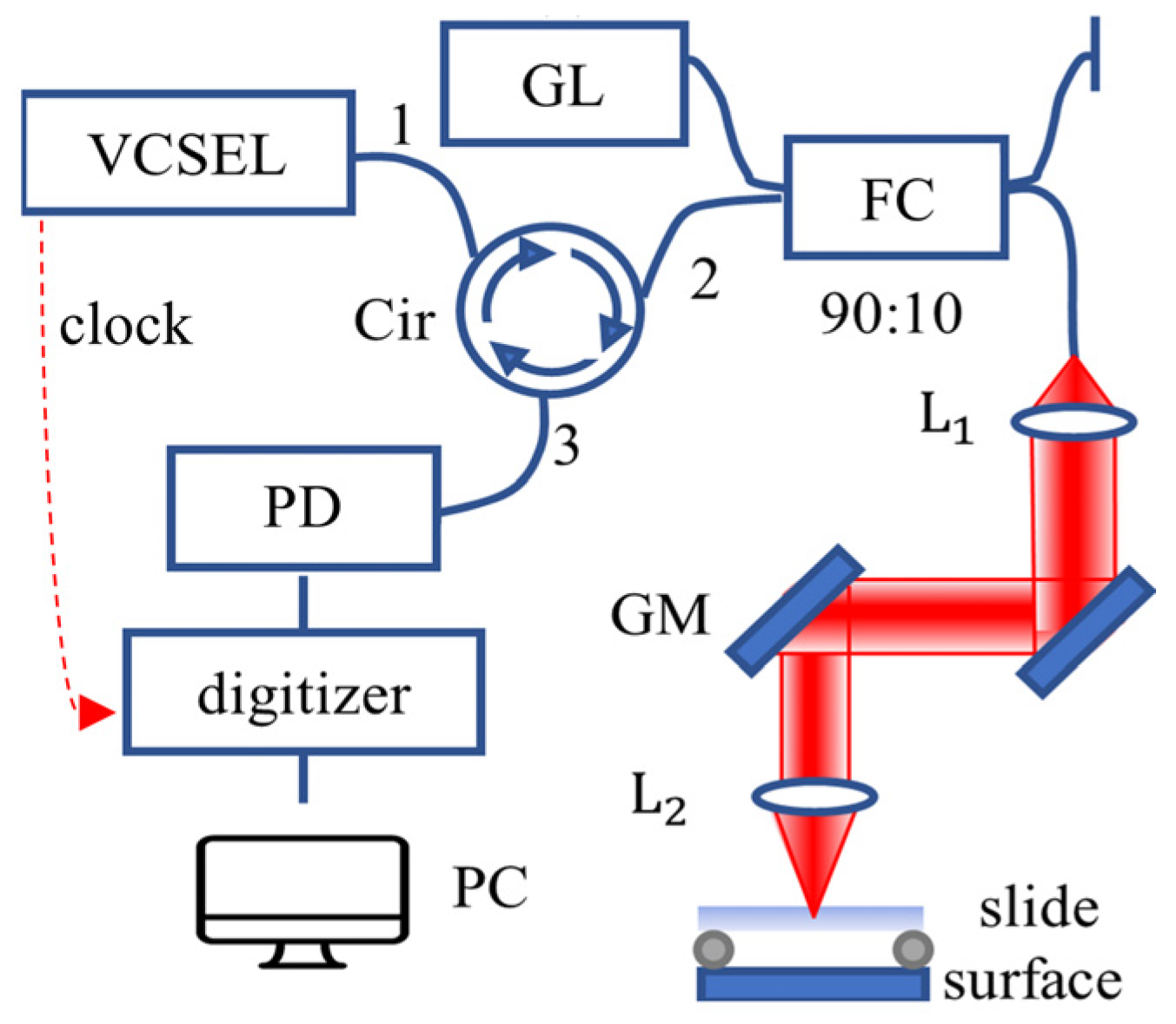
3]. For SS-OCT, the components with different wavelengths are decomposed by the swept source in the time domain, and the spectrum is converted by a photodetector and recorded by a digitizer [
4]. The axial resolution of FD-OCT, around a few microns, is determined by the spectral bandwidth. Low axial resolution makes it difficult to meet the requirements of high-precision surface profile measurement.
Phase Microscopy (PM) is a technique that provides high axial sensitivity. PM combines spectral interference and common-path structure, retrieving OPD through phase information [
5]. Since PM uses the same optical system as FD-OCT, it also has two general implementations: Spectral-Domain PM (SD-PM) and Swept-Source PM (SS-PM). The stability of the broadband light source and spectrometer in SD-PM makes it better in terms of optical alignment stability and the exact reproduction of wavenumber sampling. Therefore, PM’s most common optical configuration is SD-PM [
6,
7]. In recent years, SS-PM has gained more attention due to its greater robustness to sample motion and lower signal decay with depth [
8]. However, the mechanical wavelength tuning of the swept source creates small variations in wavelength sweeps, trigger timing, and sampling, which adversely affects the reproducibility of interference spectra and introduces serious phase noise [
9]. To suppress the phase noise introduced by the swept source and data acquisition system, some hardware-based or software-based methods are proposed: Hardware-based methods mainly involve employing buffered Fourier domain mode-locked lasers [
10] or utilizing synchronous sampling techniques [
11]. Software-based methods are proposed to avoid the need for high-quality swept light sources or high-precision synchronization devices [
12]. For example, Braaf et al. proposed a correction method based on the inverse Fourier transform [
13]; however, this method can only correct the spectral shift in a small range due to phase wrapping. Shangguan et al. used cross-correlation operations to align interference spectra, but this method can only achieve alignment at the pixel level and cannot correct deviations at the sub-pixel level [
14].
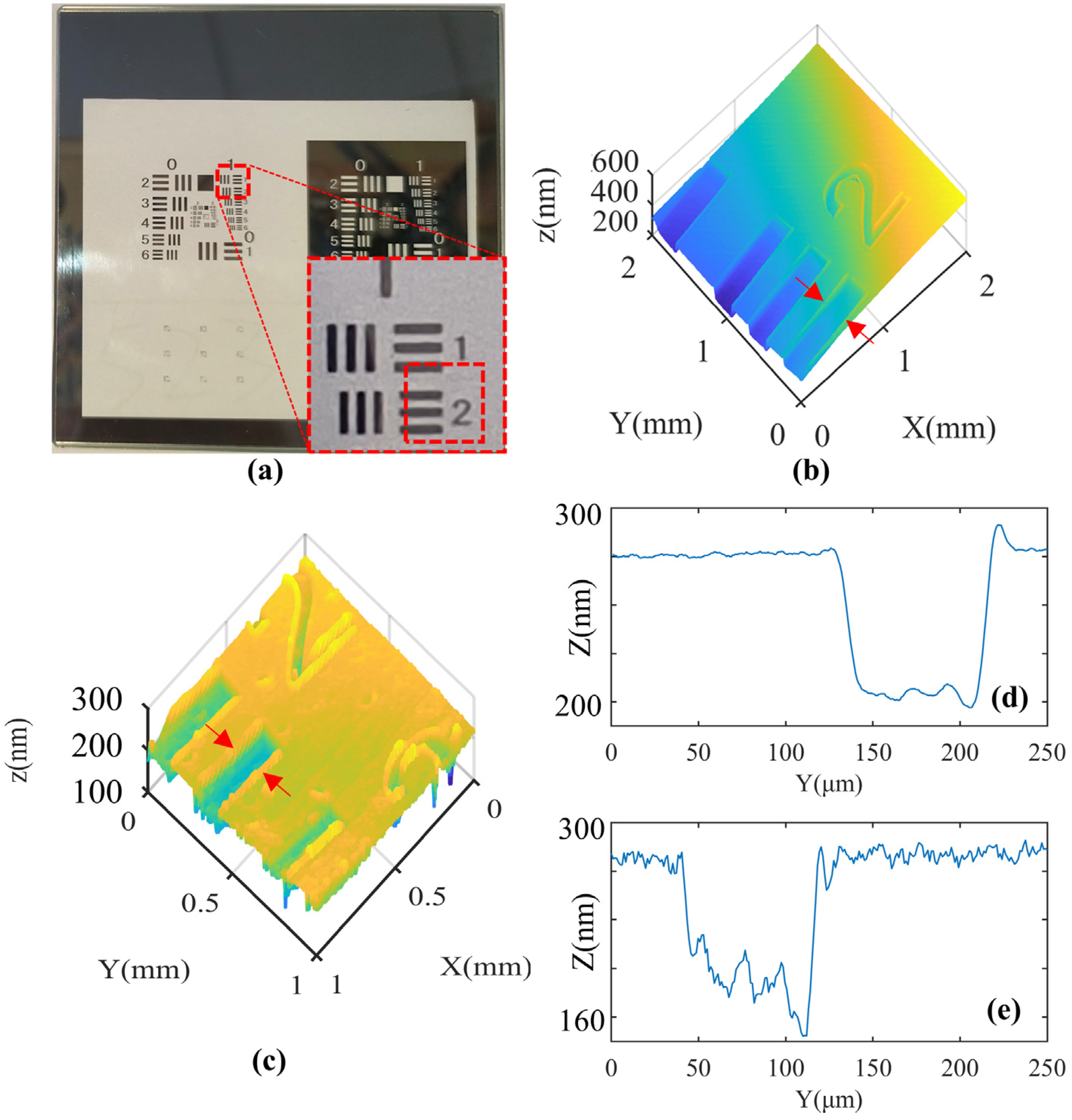
In this paper, we propose a software post-processing method to eliminate phase noise in SS-PM. This method does not require additional optical elements or reference spectra to provide phase calibration signals. This algorithm eliminates phase noise in the spectrum through specific folding operations and achieves a displacement sensitivity of 72 pm in the air. The feasibility of this method has been demonstrated by measuring the surface profile of an air wedge and a resolution target. This initial demonstration indicates that SS-PM has the potential to achieve picometer-sensitivity surface profile measurements.
2. Methods
In surface profile measurement, the reflection from the sample surface serves as the sample arm signal. Consequently, the detector signal contains a single-frequency interferometric component whose frequency is linearly encoded with the optical path difference (OPD). The instability of the swept source and data collection system leads to a random shift of the A-line in k-space.
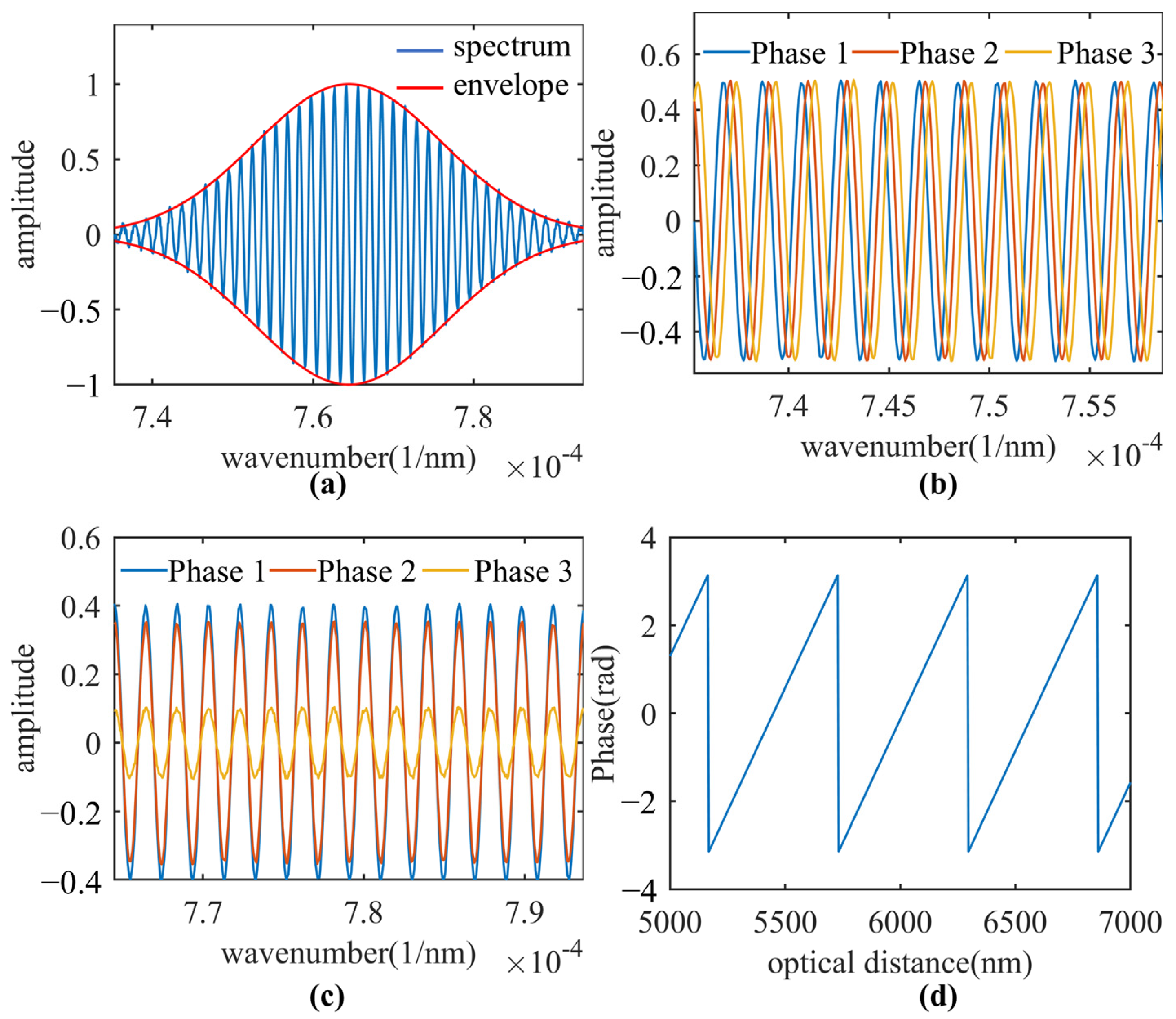
Figure 1a shows two spectra with different initial phases and the same OPD. In the case of a single sample reflector and an unstable interferometric system, this interferometric component
is given by:
where
is the wave number;
is the source power spectral density;
is the reference arm reflectivity;
is the reflectivity of the sample surface;
is the detector responsivity;
is the electric charge;
is the refractive index;
is the phase noise introduced by the swept source;
is the free distance between sample surface and reference reflector;
is the resolution of the FFT;
is the spectral bandwidth in k-space [
2];
is a positive integer,
is an integer multiple of the discrete sampling interval in the A-Scan;
is the sub-resolution deviation position of the sample surface away from
; the change of
is mainly reflected in the phase. The Fourier transform
of the spectrum is A-Scan that has a peak value at
:
where
is the source center wave number;
is the imaginary unit;
is the unity-amplitude coherence envelope function; the phase term
of
is
. When
, the phase term
is a linear function of the sub-resolution deviation
. The variation of the sub-resolution deviation
can be accurately calculated by measuring the phase variation.
Figure 1b shows the linear function between the sub-resolution deviation
and the phase
in the range of [−pi, pi]. Unfortunately, the linear function between
and
is destroyed by the phase noise
. Therefore, SS-PM cannot directly measure the phase
to calculate
.
Figure 1c shows the relationship between
and
under the influence of phase noise.
Firstly, we need to extract the cosine term
from the original spectrum
; this involves removing the envelope of spectrum in Equation (1). A method based on spline interpolating is used for the envelope estimation [
15]. First, in order to eliminate erroneous maxima and minima caused by shot noise, the interference spectrum is smoothed by convolution with a Hanning window. Then, we calculate the upper envelope
and lower envelope
by spline interpolating the maxima and minima of the smoothed spectrum, respectively. Using these two envelopes, we extract the cosine term from Equation (1):
Here,
is the cosine term without an envelope;
Figure 2a shows the envelopes calculated by spline interpolation.
To eliminate the phase noise
, a folding operation is introduced:
where
is the midpoint of the cosine term
;
is the latter half of
;
is the reversed first half of
;
is the distance between the symmetry points (
and
) and the midpoint, and its domain is [0,
/2]; the folding operation is a summation of symmetric points in the cosine term
. Each pair of points symmetric about a middle point are added together. The folding operation eliminates phase noise in the spectrum and produces a cosine signal
with an amplitude of
, an initial phase of zero, and a length of
/2 + 1.
Figure 2b shows three spectra with the same OPD under phase noise. The phase noise in these spectra is eliminated by a folding operation, as shown in
Figure 2c. The time complexity of the folding operation is O(
N/2), where
N is the length of the spectrum. This means that the folding operation has very little impact on real-time performance. SS-PM applies the Fourier transform to the zero-filled cosine term
to obtain A-Scan as follows:
Here, the coherent ghost image is disregarded for simplicity;
denotes the Fourier transformation of the rectangular window;
represents distance;
is the unit impulse function with a peak value at
;
represents convolution;
is the amplitude spectrum of the Fourier transformation;
is the phase spectrum, which is used to calculate the sub-resolution position
. In actual calculations, the FFT samples the amplitude spectrum at intervals of
. The nearest sampling point at the peaked value
is given by:
The folding operation eliminates the phase noise in the
compared to Equation (2). This method restores the linear function between the sub-resolution position and the phase term. The sub-resolution position change of the surface profile can be measured with the phase difference between two adjacent A-lines:
Here, denotes the phase operator.
Figure 2d shows the phase variation with a sub-resolution position, which proves that the folding operation can effectively eliminate the phase noise introduced by the swept light source. The folding operation eliminates the phase noise introduced by the swept source. Therefore, OPD can be obtained using phase information, indicating that the presented algorithm can effectively improve axial sensitivity. By using linear regression of the phase in the Hilbert domain [
16] or the least squares method in the spectral domain [
5] to remove phase wrapping in SS-PM, the measurement depth range of SS-PM can reach a few centimeters.
4. Discussion
In SS-PM, the spectrum
contains the phase noise
introduced by unstable interference systems and the shot noise introduced by the photodetector. The influence of phase noise
is more significant than shot noise for sub-resolution position measurement. The swept source with mechanical wavelength tuning generates tiny variations in wave number sweeps, trigger timing, and sampling, which manifest as random shifts of the spectrum in k-space.
Figure 8a shows the influence of phase noise in the complex plane of the FT.
is a signal vector corresponding to the FT of the spectrum. The angle between
and the positive real axis is used to calculate the sub-resolution position. The gray circular region in
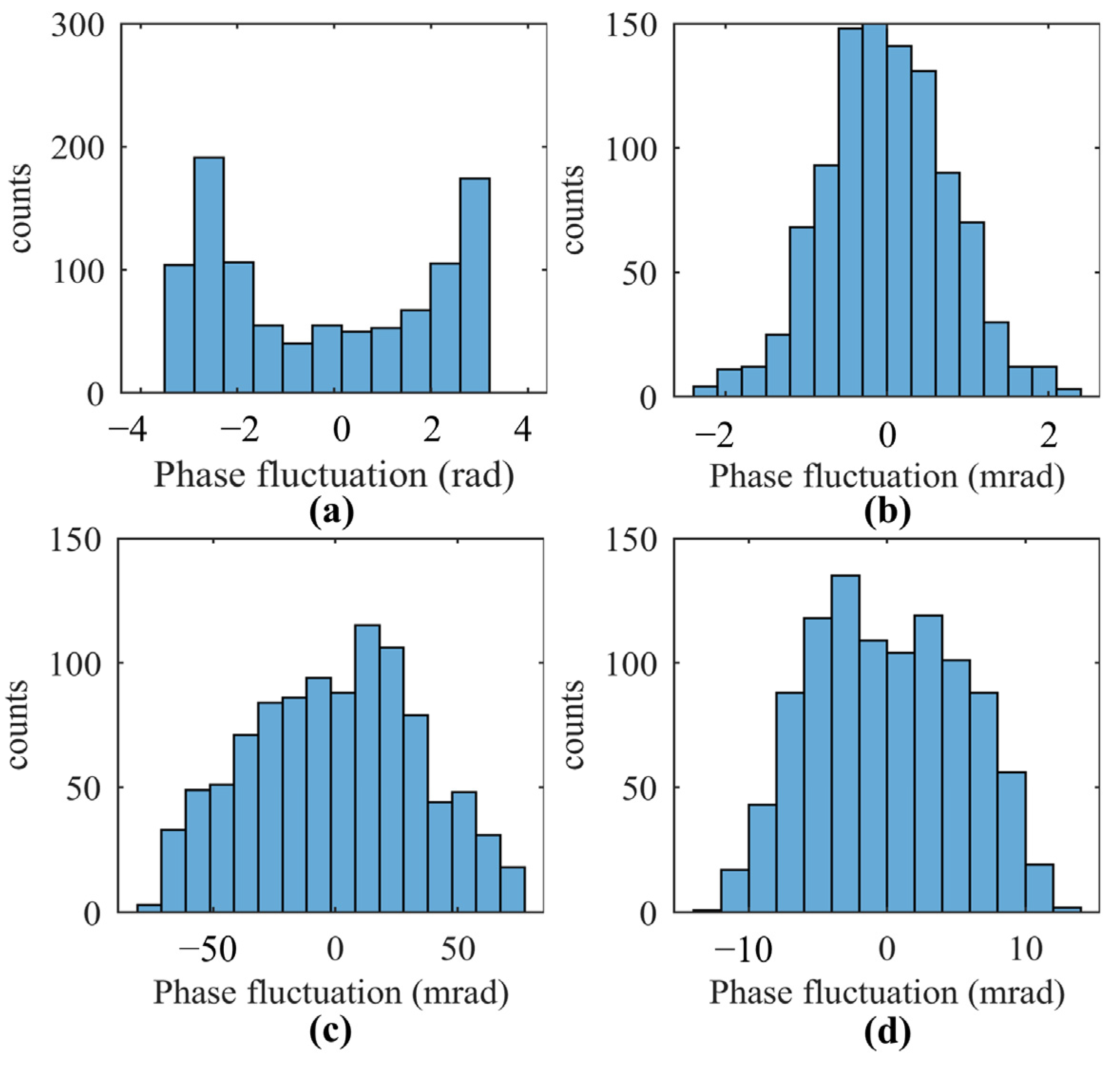
Figure 8a represents the fluctuation range of the phase noise, which corresponds to the histogram in
Figure 4a. The phase noise acts as a twiddle factor in the complex plane of the FT, rotating the result of the Fourier transform
by a random angle around the origin of the coordinates. The large fluctuation range of the phase noise conceals the real angle of
, making it difficult to use uncorrected spectra for sub-resolution position measurement.
After the phase noise is eliminated by the folding operation, the fundamental lower limit of the sub-resolution position change (position sensitivity) is determined by the shot noise. Shot noise can be approximated as additive, independent Gaussian white noise [
1]. At
, the Fourier transform of the shot noise is:
Here,
is the total source power;
is the random phase of the shot noise;
is the integration time.
Figure 8b shows the influence of shot noise in the complex plane of the FT. The vector of the practical spectrum is obtained by the vectorial addition of the signal vector
and the shot-noise vector
in the complex plane. The angular orientation
between the signal vector and the noise vector is random. Since the signal vector has a certain amplitude and angle, the shot-noise vector can be decomposed into a vertical component (
) and a parallel component (
). Under the premise that the intensity of
is much less than the intensity of
, the influence of the parallel component can be neglected. The vertical component changes the angle of the actual spectrum by
. The smallest observable change in the phase of the signal vector is determined by the shot noise. In other words, an observable change in the signal phase must be larger than
. The fundamental lower limit of the sub-resolution position change is:
The swept source decomposes the components with different wavelengths in the time domain, and the integration time
of a single pixel in SS-PM is much shorter than that in conventional SD-PM. Equation (8) shows that the intensity of the shot noise is proportional to the integration time, which means that SS-PM can achieve a lower shot noise and a better fundamental lower limit of the sub-resolution position change than traditional SD-PM. To quantitatively evaluate the performance differences between SS-PM and SD-PM, we continuously acquired 1000 interference spectra between the beams reflected from the top and bottom surfaces of a stationary glass slide using the SD-PM system. The histogram of the OPD is shown in
Figure 9. The standard deviation of the calculated phases is 0.89 mrad, while the standard deviation of SS-PM using the presented method is 0.69 mrad. Therefore, it is observed that the sensitivity of SS-PM is superior to that of SD-PM due to the reduced shot noise.


