Article

Research on Tracking Control Technology Based on Fuzzy PID in Underwater Optical Communication

1
School of Optoelectronic Engineering, Changchun University of Science and Technology, Changchun 130022, China
2
National and Local Joint Engineering Research Center of Space Optoelectronics Technology, Changchun University of Science and Technology, Changchun 130022, China
3
National Key Laboratory of Electromagnetic Space Security, Tianjin 300308, China
4
China Electronics Technology Group Corporation 34th Research Institute, Guilin 541004, China
5
Qian Xuesen Laboratory of Space Technology, China Academy of Space Technology, Beijing 100094, China
*
Authors to whom correspondence should be addressed.
Photonics 2024, 11(10), 957; https://doi.org/10.3390/photonics11100957
Submission received: 9 September 2024 / Revised: 7 October 2024 / Accepted: 7 October 2024 / Published: 12 October 2024
(This article belongs to the Section Optical Communication and Network)

Abstract

:
In order to realize effective laser communication on underwater mobile platforms, the active tracking and alignment technology of underwater laser communication (UWLC) is studied. Firstly, the servo control principle of the UWLC system is analyzed. Secondly, aiming at underwater disturbance, an adaptive fuzzy PID controller is designed to realize parameter self-tuning, thereby improving the system’s anti-disturbance ability. The designed algorithm was simulated, and the simulation results show that the adaptive fuzzy PID algorithm has better anti-disturbance ability and tracking performance than the traditional PID. Finally, an experimental platform was built for dynamic tracking experiments, and the results show that the dynamic tracking accuracy of the designed control algorithm was improved by 30.29% compared with the traditional control algorithm, which provides a certain reference for the development of laser communication on underwater moving platforms.

1. Introduction

In order to realize the development and utilization of marine resources and the detection and protection of the marine environment, an ocean detection and perception system composed of various types of underwater equipment has been developed [1]. Underwater wireless communication technology is widely used in marine exploration systems. There are three types of underwater wireless communication technologies: electromagnetic wave communication, acoustic communication, and underwater wireless optical communication (UWOC). Electromagnetic waves attenuate greatly in water, resulting in a very short transmission distance, making it almost impossible to communicate using electromagnetic waves underwater. Acoustic communication is widely used, but due to the multipath effect, Doppler effect, etc., its data transmission rate is only in the order of kbps or even lower. UWOC can make up for the shortcomings of electromagnetic wave communication and acoustic communication, and has great development potential. UWLC technology has become an important research direction in underwater wireless communication technology due to its advantages of high bandwidth, high communication rate, and resistance to electromagnetic interference [2]. However, when the equipment of the communication system is working underwater, it will be disturbed by random waves and its attitude will change. And when a laser is transmitted underwater, it is easily affected by turbulence, bubbles, underwater organisms, etc. These factors make it difficult to establish stable and effective communication links [3]. Therefore, it is necessary to develop a fast and stable tracking and alignment technology for laser beams.
Most of the research on alignment technology in UWOC is based on the light-emitting-diode (LED) systems. Some researchers have adopted multi-input–multi-output technology based on LED arrays or detector arrays, which avoids alignment problems by simultaneously increasing the radiation range of the emitting light source and the acceptable range of the receiving end [4,5,6,7]. However, such a system occupies a large space and has a complex structure, which is not conducive to flexible use in underwater environments. Huang Xuan et al. have studied an UWOC system combining Laser Diodes (LDs) and LEDs to reduce the difficulty of alignment, in which the LEDs are used for coarse tracking and LDs are used for fine tracking [8]. P. B. Solanki et al. have designed an UWOC system based on LEDs, which uses the extended Kalman filter algorithm to estimate the relative angle between the receiver and transmitter through the light intensity distribution characteristics at the receiving end, and a simple proportional controller is designed for alignment. The target can be aligned when the transmitter is 1.25 m away from the receiver and moves at a speed of 1°/s [9]. Xinyu Deng designed a tracking platform for UWLC, which uses the mean shift algorithm combined with Kalman filtering to obtain the target offset, and the proportional control equation corresponding to the target offset is established for alignment. The target can be tracked within 2.5 m [10]. Jiaxing Wang built a set of tracking control systems for UWLC and realized the tracking and alignment of the light spot within 1 m through proportional control; the azimuth alignment accuracy here was 170 μrad and the pitch alignment accuracy was 420 μrad [11].
Compared with LEDs, LDs have a smaller divergence angle and a longer transmission distance, making them more suitable as a transmitting light source, but at the same time they have higher requirements for tracking and alignment [12]. At present, most UWLC research uses manual adjustment methods to align the optical path, and there is little research on active tracking and alignment. Proportional Integral Derivative (PID) algorithms are commonly used in the field of servo control to track targets. The parameters of the PID algorithm are fixed, which results in an untimely response to disturbances and low tracking accuracy [13].
This paper analyzes the principle of tracking control in UWLC, and studies the equivalent value of the disturbance caused by random waves to which the tracking system of UWLC is subjected when working underwater. Based on the equivalent disturbance characteristics, an adaptive fuzzy PID control algorithm is designed to achieve the self-tuning of controller parameters. The designed control algorithm is applied to the tracking control system of UWLC, which improves the system’s anti-disturbance capability and tracking accuracy, providing a guarantee for the ultimate realization of communication.

2. Servo Control Principle of UWLC

The Acquisition Pointing and Tracking (APT) technology in space laser communication has become relatively mature, but its structure is complex and costly, making it difficult to directly apply it to UWLC [14]. In recent years, the combination of optoelectronic tracking technology and UWLC technology has been applied underwater, allowing the stable reception of laser signals at the receiving terminal. Figure 1 shows a structural block diagram of the UWLC system. The information is modulated in the laser communication transmission module, and then the modulated signal is loaded onto the laser source for transmission. The laser reaches the receiving terminal through the underwater channel. The photoelectric tracking module tracks and aligns the laser beam until the laser spot is aligned with the center of the target surface at the receiving end. The laser communication receiver module performs photoelectric conversion, demodulation, and other processing steps on the received signal laser.
In order to realize the high-accuracy tracking of the laser beam underwater, the photoelectric tracking system adopts a double closed-loop composite control strategy for the position loop and velocity loop. The control block diagram is shown in Figure 2. In the position loop, the difference between the target position and the output position is adjusted by the position loop controller and output to the velocity loop. In the speed closed loop, the difference between the input value of the speed loop and the feedback value of the speed loop is adjusted by the speed loop controller and output to the motor. The motor drives the tracking turntable, causing it to rotate to the corresponding position. The feedback value of the speed loop is the angular velocity generated when the tracking turntable is disturbed by external factors.
The torque motor is the actuator of the UWLC optoelectronic tracking control system. The motor and load are rigidly connected and can be viewed as a single unit. We here establish its mathematical model. The voltage balance equations of the motor are shown in Equations (1) and (2), which can be derived from Kirchhoff’s voltage law.
U = R I + L d I d t + E ,
E = K e ω
where U is the armature voltage, R is the armature resistance, I is the armature current, L is the armature inductance, E is the reverse Electromotive Force (EMF) of the armature, K e is the back EMF coefficient of the motor, and ω is the motor speed.
Assume M a is the electromagnetic torque of the motor, M d is the inertia moment of the load, K T is the electromagnetic torque coefficient of the motor, and J is the moment of inertia. We can then construct the following equations:
M a = K T I ,
M d = J d ω d t
According to the torque balance equation of the motor, we can derive
K T I = J d ω d t ,
By performing Laplace transform on Equations (1) and (5), we can derive the transfer function of the tracking control system as follows:
ω ( s ) U ( s ) = 1 / K e T m T e s 2 + T m s + 1 ,
where T m = R J K e K T , T e = L R .
By analyzing the principle of photoelectric tracking control and modeling the controlled object, we can build a simulation platform to verify the effectiveness of the designed algorithm.

3. Design and Simulation of Adaptive Fuzzy PID Algorithm Based on Underwater Disturbance

3.1. Underwater Disturbance Analysis

The interaction between deep-sea fluids and underwater equipment is one of the key issues in the tracking and control field of UWLC. It is urgent to clarify the characteristics of the underwater disturbance, which is essential for the design of controllers for tracking and control systems. Ocean waves are the main source of disturbance that causes the swaying of underwater equipment. The disturbance value is large, and it has uncertainty and randomness. Therefore, the disturbance caused by waves to the tracking system of underwater laser communication is analyzed.
According to the statistical law of ocean waves, it can be considered that ocean waves are composed of many simple harmonic waves with different frequencies. Therefore, the wave height can be obtained by the linear superposition of sine waves, and its expression is as follows [15]:
η ( t ) = n = 1 a n cos ( ω n t + ε n ) ,
where a n and ω n are the amplitude and angular frequency of the nth simple harmonic wave, respectively, ε n is a random phase angle within the range of ( 0 , 2 π ) , and t is the time.
The harmonic amplitude can be obtained through the wave energy spectral density function. Many scholars have conducted systematic research on the wave spectrum model and proposed a semi-empirical and semi-theoretical wave spectrum model based on measured data. In this paper, we adopt the wave spectral density formula recommended by the International Towing Tank Conference (ITTC), and its specific expression is shown in Equation (8) [16]:
S ( ω ) = 8.1 × 10 3 g 2 ω 5 exp ( 3.11 / h 1 / 3 2 ω 4 ) ,
where g is the gravitational acceleration, h 1 / 3 is the meaningful wave height, and ω is the angular frequency of the wave.
Suppose that the optoelectronic tracking system of UWLC is installed on the SUBOFF submarine model designed by the US Defense Advanced Research Projects Agency. The equivalent disturbance of the tracking and control system can be obtained by Equation (9):
α = arctan η ( t ) l ,
where l is the length of the SUBOFF submarine, which is 104.5 m [17].
Assuming the simulated sea state is level 3, the meaningful wave height is 0.88 m. In order to meet the simulation requirement of a sufficient ratio of wave spectrum energy to total energy, the simulation frequency band of the wave spectrum is selected as 0.05~5.5 rad/s. The equivalent disturbance obtained by simulation is shown in Figure 3.

3.2. Design of Adaptive Fuzzy PID Algorithm

The structure of the conventional PID control algorithm in the field of servo control is shown in Figure 4. r(t) is the target value, e(t) is the error value at the current moment, u(t) is the output value at the current moment, and c(t) is the final output value of the system. The PID algorithm corrects the system’s errors through a proportional section, improves the system’s steady-state accuracy through an integral section, and overcomes the system’s inertia lag through a differential section to enhance the system’s stability.
According to Figure 4, the control law of the PID algorithm is shown in Formula (10).
u ( t ) = k p e ( t ) + k i 0 t e ( t ) d t + k d d e ( t ) d t ,
where k p , k i and k d are the proportional coefficient, integral coefficient, and differential coefficient, respectively. k p can improve the response speed and tracking accuracy of the system, but if it is too large, it will cause overshoot and damage the system’s performance. k i can eliminate the steady-state error of the system, but if it is too large, integral saturation will occur, causing the dynamic performance of the system to deteriorate. k d only affects the rate of change of the system error, which can suppress the change of the error in advance, but if it is too large, it will affect the anti-disturbance ability of the system.
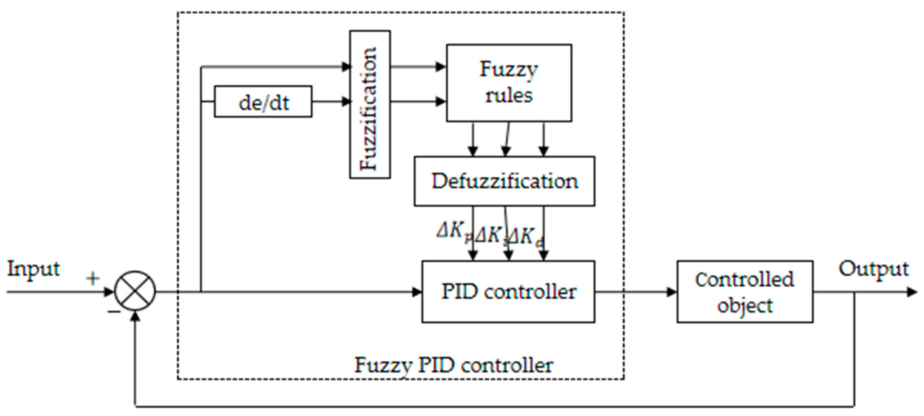
The parameters of the PID algorithm are fixed, and its capacity to respond to external disturbances is not ideal. In order to cope with underwater disturbances, the fuzzy control strategy is combined with the PID algorithm to achieve the self-tuning of the controller parameters, giving the system a certain degree of intelligence and improving the dynamic performance of the system. Aiming at the underwater disturbance of the optoelectronic tracking control system of the UWLC, an adaptive fuzzy PID controller is designed. Its structure consists of two parts, fuzzy control and parameter adaptive PID, as shown in Figure 5.
The expressions for the parameters of the adaptive fuzzy PID controller are shown in Equation (11):
K p = K p + Δ K p K i = K i + Δ K i K d = K d + Δ K d ,
where K p , K i and K d are the initial values of proportional, integral and differential. Δ K p , Δ K i and Δ K d are the adaptive variations of proportional, integral and differential.
Firstly, we have fuzzified the input and output. The two inputs e and ec of the fuzzy controller are mapped to a real value in the fuzzy domain through quantization. The quantization functions are shown in Equations (12) and (13). We set the fuzzy domain to [−6,6]. We select fuzzy subsets and membership functions to obtain the membership degree of the input on the fuzzy subset. We then convert the original exact values into fuzzy values and represent them with corresponding fuzzy sets. When fewer linguistic variables are selected in the fuzzy subset, the control rules are rough and the control performance is poor. The more linguistic variables are selected in the fuzzy subset, the better the control performance, but the response of the control rules becomes more complex. When the number of designed linguistic variables is 7, this ensures that all input and output states are covered, and the accuracy and stability of the tracking control system of UWLC can be taken into account at the same time. Therefore, the fuzzy subsets of input and output designed in this paper are {NB, NM, NS, ZO, PS, PM, PB}. Trigonometric functions have high sensitivity and can respond to input changes in a timely manner [18]. This can enable the system to better cope with external disturbances, so this paper chooses the triangular membership function.
f ( e ) = 6 e V max V min ,
f ( e c ) = 6 e c 2 ( V max V min )
where V max is the maximum value of input, V min is the minimum value of input.
Secondly, fuzzy rules are designed and fuzzy reasoning is performed to derive fuzzy outputs based on the fuzzy rules. The fuzzy control rule is the core of the adaptive fuzzy PID controller and is derived from expert experience. Based on the functions of K p , K i , and K d described above, the fuzzy control rules are designed as follows: When the value of input error e is large, in order to endow the system with a faster response speed and good bandwidth, a larger K p and a smaller K d should be selected. At the same time, in order to prevent the system from overshooting, a smaller K i value should be selected. When the value of input error e is moderate, K p should be appropriately reduced, K i should be moderate, and K d should be small in order to ensure the response speed and reduce the overshoot of the system’s output. When the value of input error e is small, in order to ensure that the system has good steady-state performance, larger K p and K i values should be selected. At the same time, in order to avoid system oscillation and consider the system’s anti-interference performance, the K d value should be adjusted according to the error change rate e c . When the value of input error e c is large, K d takes a smaller value, and when the value of input error e c is smaller, K d can take a larger value. Based on this, we can obtain the fuzzy control rules for Δ K p , K i , and K d , as shown in Table 1, Table 2, and Table 3, respectively. The designed control rule can ensure that the tracking control system of UWLC eliminates the error as quickly as possible when the error is large, and ensures the stability of the system when the error is small.
Finally, clear values of Δ K p , K i and K d are obtained through defuzzification. This paper uses the centroid method for defuzzification, and its expression is shown in Equation (14).
u c = X ( u ) u d u X ( u ) d u
Here, u is the fuzzy variable element, and X ( u ) is the membership degree of u .

3.3. Simulation Verification

In order to verify the effectiveness of the control algorithm proposed in this paper, traditional PID and adaptive fuzzy PID are used to carry out simulation verification in Simulink. We compare the output responses of two control algorithms by inputting a step signal of 1°. The output response is shown in Figure 6. When using the PID control algorithm, the steady-state time of the output response is 0.1 s, and the overshoot is 12.5%. When using the fuzzy PID control algorithm, the steady-state time of the output response is 0.06 s, with almost no overshoot. The comparison shows that the fuzzy PID control algorithm has better dynamic performance.
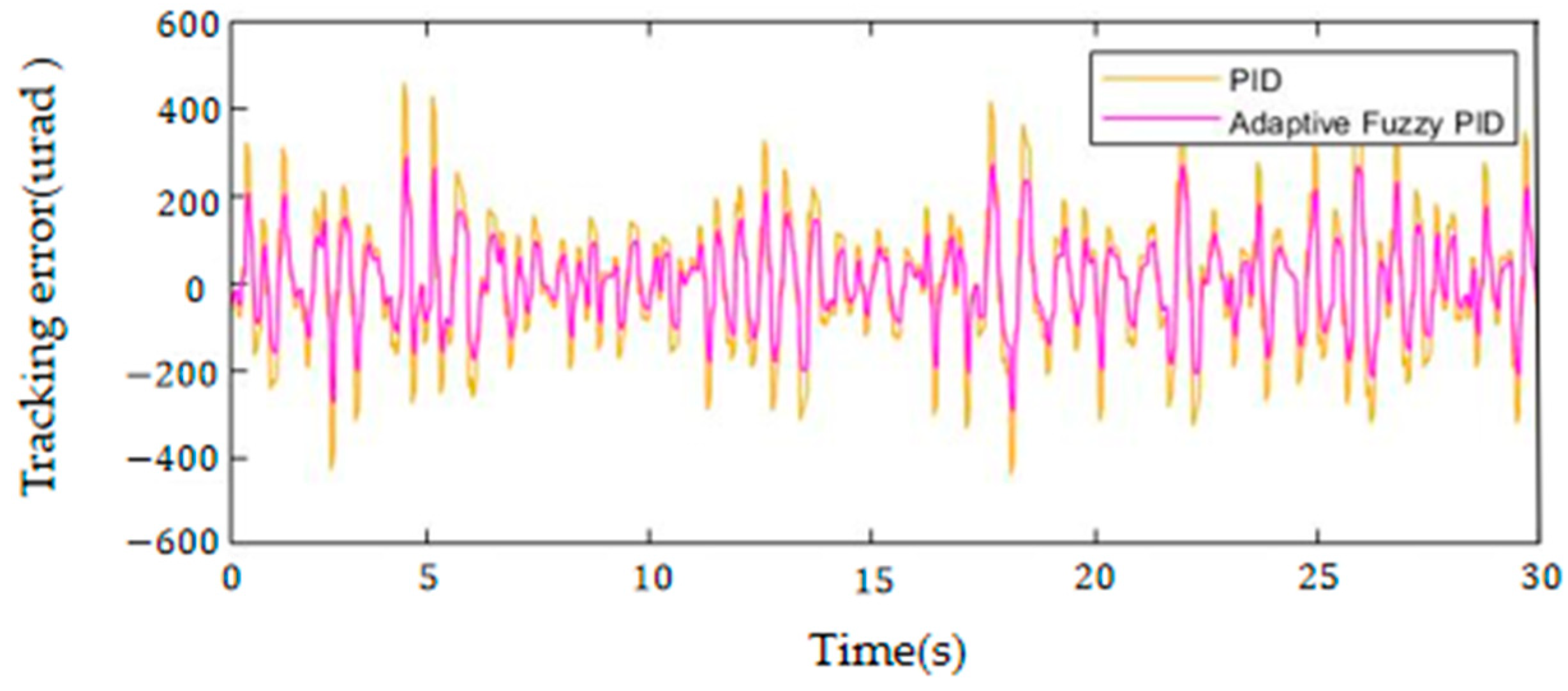
The system simulation model is built in Simulink according to the control block diagram shown in Figure 2. The equivalent disturbance derived above is applied to the system to simulate the change in angular velocity of the tracking system when it is disturbed by seawater. The PID control algorithm is used for the position loop all the time, and the PID control algorithm and the adaptive fuzzy PID control algorithm are both used for the speed loop. The parameters of the PID algorithm are debugged using the trial and error method until the best tracking effect is achieved. This parameter is used as the initial parameter value of the adaptive fuzzy PID algorithm. The adaptive fuzzy PID control algorithm can adaptively adjust the controller parameters based on the initial parameters according to the changes in the input. Figure 7 shows the adaptive results Δ K p , Δ K i and Δ K d . Comparing the impacts of the two control methods on the system’s tracking performance, the tracking errors of the two control methods are shown in Figure 8. The Root Mean Square (RMS) of the tracking error of the traditional PID control is 182.8 μrad and the RMS of the tracking error of the adaptive fuzzy PID control is 121.4 μrad. Comparing the simulation results, the adaptive fuzzy PID control algorithm has higher tracking accuracy, which is improved by about 33.6% compared to the traditional PID control algorithm.

4. Experimental Verification

4.1. Tracking Experiment

The computational complexity of an algorithm can be measured by its time complexity. The time frequency of adaptive fuzzy PID algorithm statements is analyzed. The adaptive fuzzy PID algorithm statement mainly includes three functions: the function of fuzzification, the function of fuzzy reasoning and the function of defuzzification. The fuzzification function quantifies the input error and obtains its membership degree in the fuzzy set. The time complexity of this function is O(1). The fuzzy reasoning function needs to obtain the membership degree of the output based on fuzzy rules, which requires multiple iterations and calculations. The time complexity of the function is O(n). the defuzzification function obtains a clear output value and its time complexity is O(1). From this, it can be concluded that the time complexity of the adaptive fuzzy PID algorithm is O(n).
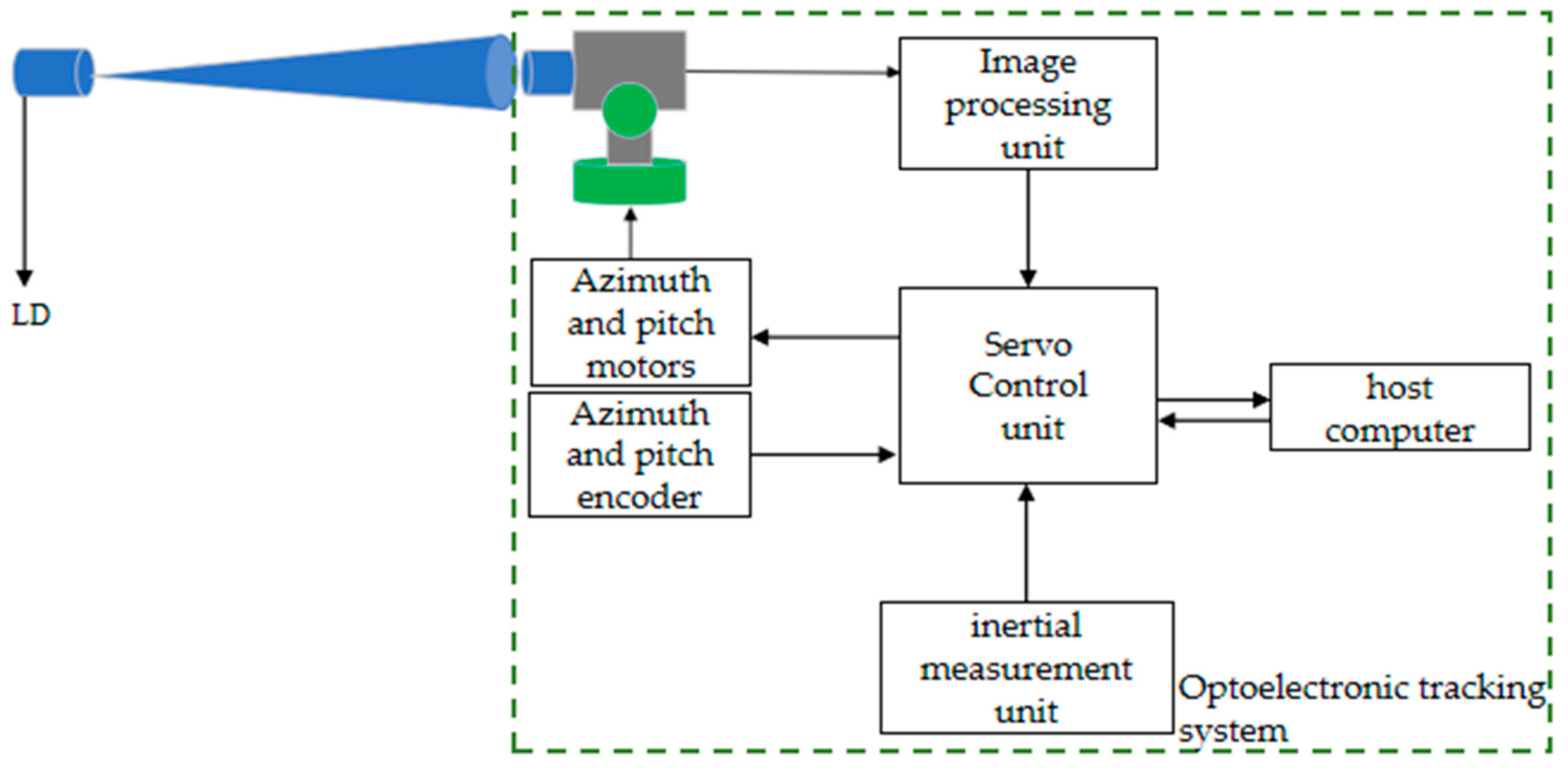
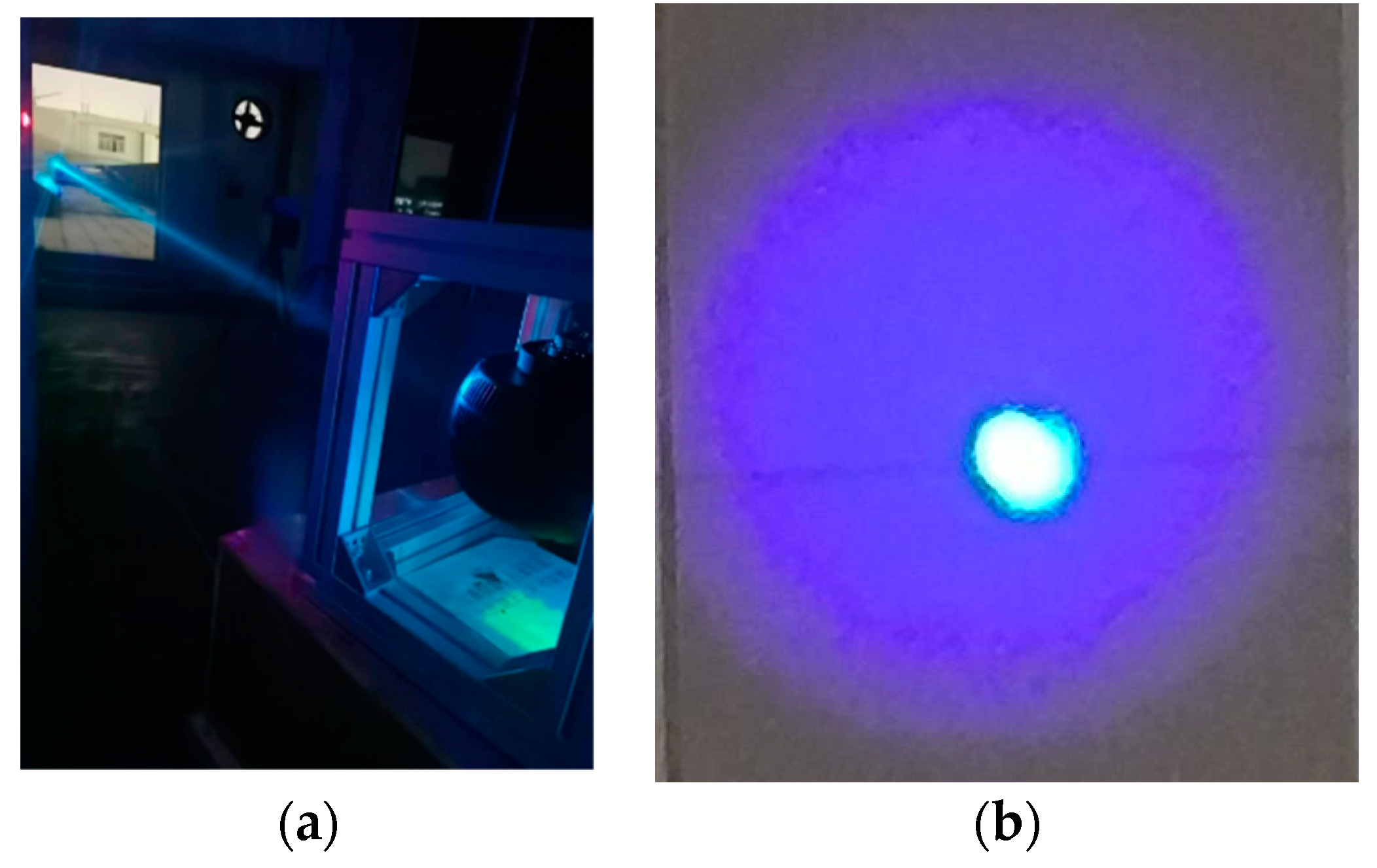
In order to verify the actual control performance of the proposed control algorithm, a tracking and control system of UWLC, as shown in Figure 9, was built for experimental verification. Figure 10a is a real product of the underwater tracking turntable. After the laser signal reaches the receiving end, the spot image is collected by the camera, and the miss distance is obtained by the image processing unit. The external disturbances to the system are measured by the inertial measurement unit. The servo control unit obtains the motor control signal based on the miss distance information and feedback information from the inertial measurement unit. The STM32F407 chip has excellent mathematical computing capabilities, so the STM32F407 chip is selected as the main control unit. The azimuth and pitch motors drive the tracking system to rotate until the laser spot is aligned with the center of the receiving detector. The encoder measures the real-time position of the motor. The tracking and control system transmits the miss distance information to the host computer through the RS-422 serial port, with a transmission frequency of 200 Hz. The host computer performs RMS statistics on the collected miss distance information to obtain the tracking accuracy. The emission light source uses 465 nm beacon light and 520 nm signal light. As shown in Figure 10b, the beacon light and signal light are designed coaxially at the transmitting end, so that the signal light is located at the center of the beacon light. The beam divergence angle of beacon light is 2°, and the beam divergence angle of signal light is 1 mrad. Tracking is performed using a beacon light with a large beam divergence angle. When the beacon light is aimed at the center of the camera’s field of view, the beacon light is also aimed at the receiving end of the photomultiplier tube.
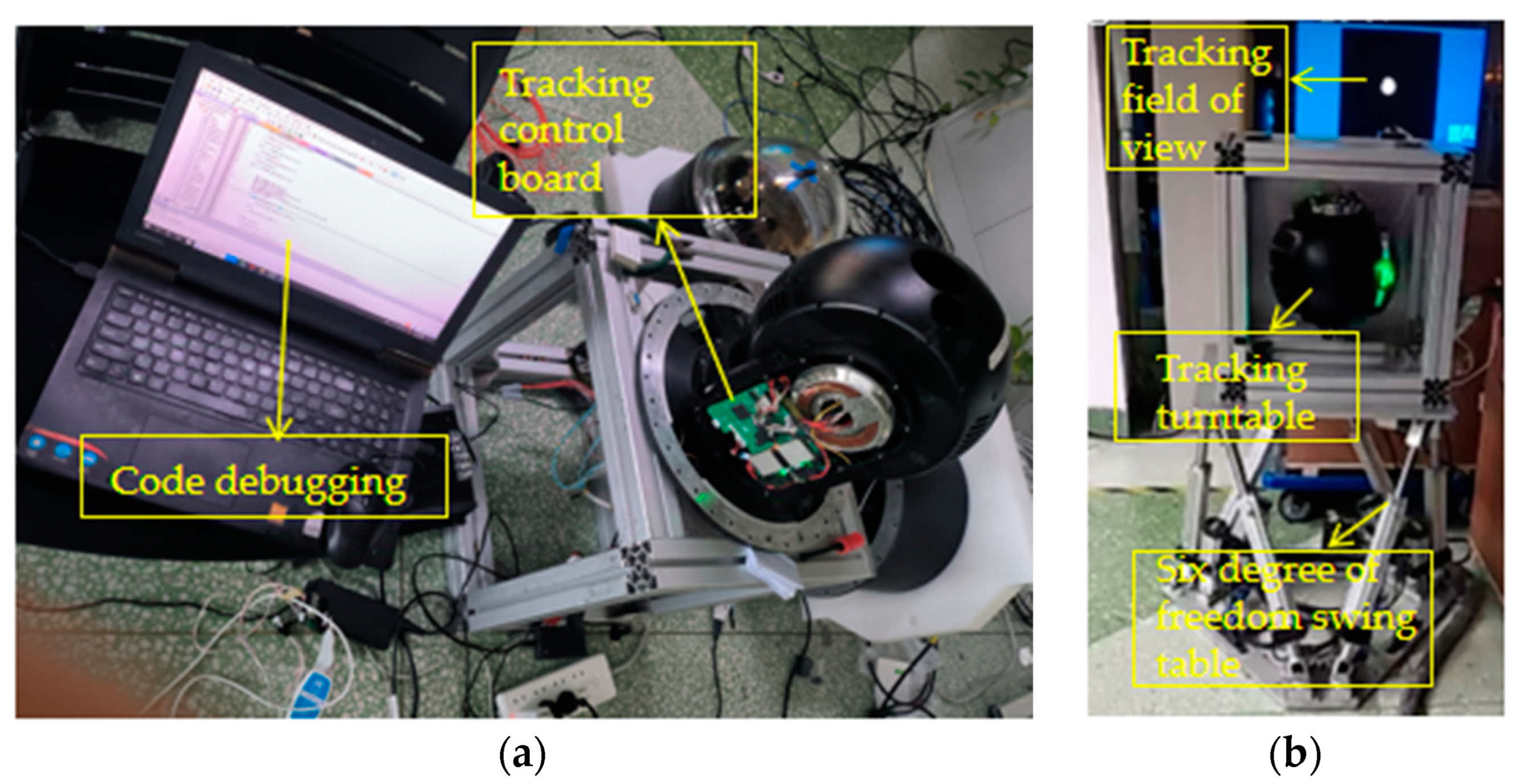
Figure 11a shows the debugging site of the tracking turntable. In order to verify the tracking performance of the designed tracking control system under disturbance conditions, the tracking turntable is fixed on a six-degree-of-freedom swing table, as shown in Figure 11b. Analyzing the disturbance obtained in Section 3.1, it is found that the disturbance is approximately a sine signal with an amplitude of 0.8° and a frequency of 0.43 Hz. The swing amplitude of the azimuth and pitch axes of the swing table is set to 0.8°, and the swing frequency is set to 0.43 Hz. To simulate the underwater disturbance experienced by the tracking turntable, Figure 12a–d shows the tracking trajectory of the target light spot, and the alignment of the light spot is completed within 2 to 3 s. The “+” in Figure 12 represents the center position of the camera’s field of view.
Figure 13 and Figure 14 show the tracking errors of the directions of azimuth and pitch when adaptive fuzzy PID and traditional PID control algorithms are adopted, respectively. When the PID control algorithm is used, the RMS of the azimuth axis tracking error is 274.77 μrad, the RMS of the pitch axis tracking error is 245.52 μrad, and the total RMS is 260.55 μrad. When the adaptive fuzzy PID control algorithm is used, the RMS of the azimuth axis tracking error is 191.51 μrad; the RMS of the pitch axis tracking error is 171.17 μrad, and the total RMS is 181.62 μrad. The experimental results show that the tracking accuracy of the adaptive fuzzy PID proposed in this paper is improved by 30.29% compared with the traditional PID, which verifies the effectiveness of the designed control algorithm.

4.2. Communication Experiment

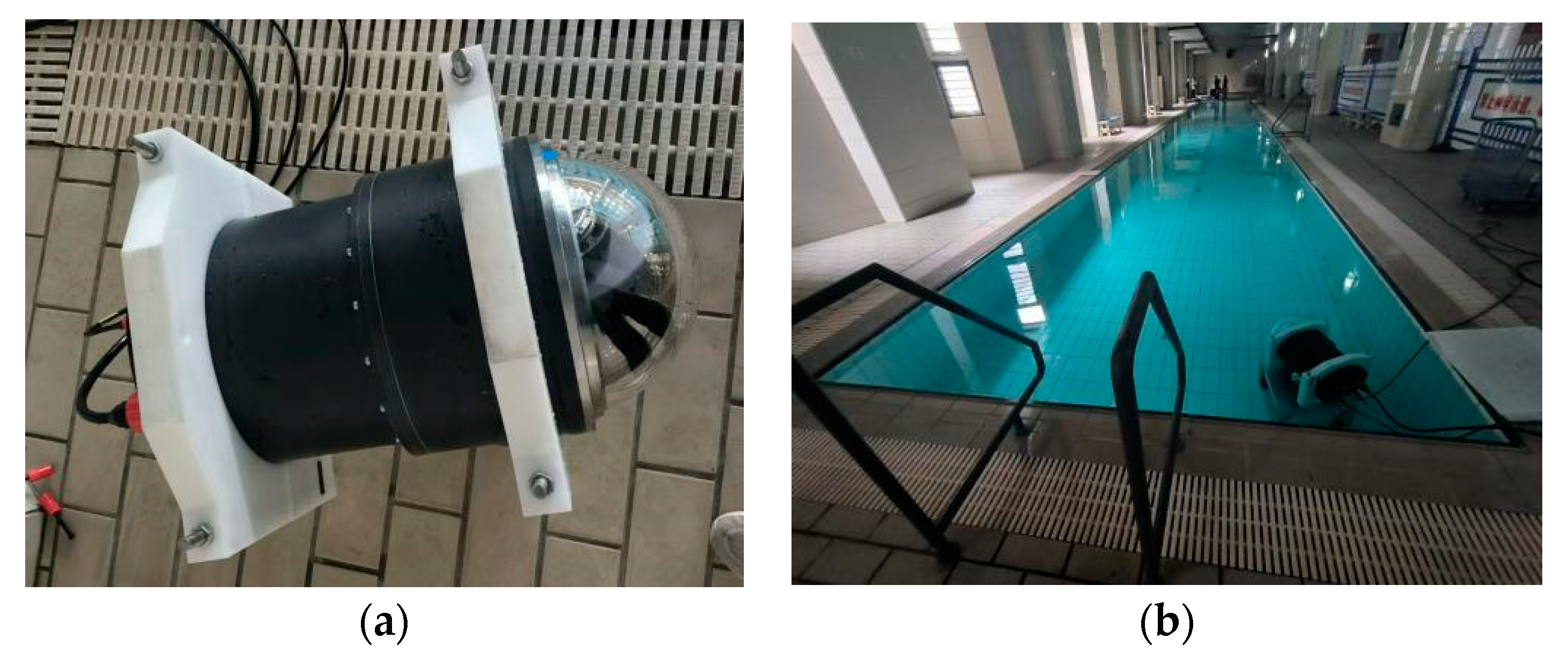
Figure 15a shows the tracking control system after watertight packaging has been included. Figure 15b shows the water pool environment used for the experiment, with a depth of 1.5 m and a length of 50 m. The tracking turntable is placed in the pool. When the laser signal enters the receiving field of view of the tracking system, the tracking control system tracks the laser beam. In order to test the communication performance of the UWLC system, a signal transmission test is carried out in the pool environment. The data coding and OOK modulation are completed at the sending end, and the output signal is loaded into the laser driver to output the modulated optical signal. After the tracking and control system completes the alignment of the optical path, the signal laser is simultaneously aligned with the center of the receiving end of the photomultiplier tube. The communication performance is analyzed at the receiving end, and the test results of the communication performance are shown in Table 4. The communication rate test results are shown in Figure 16a, and the communication bit error rate test results are shown in Figure 16b.

5. Discussion and Conclusions

In the study of UWOC, most researchers use multiple-input, multiple-output technology to avoid the problem of tracking and alignment. Some researchers have built a tracking and control system for UWOC, and based on this, they have conducted preliminary verifications of tracking and alignment through simple proportional control. However, the tracking distance is short, and the underwater disturbance is not considered, so the anti-disturbance ability is poor.
In this paper, the dynamic tracking control technology of UWLC is studied, which improves the tracking accuracy and anti-interference ability of the tracking and control system of UWLC. The underwater disturbance characteristics are analyzed. Aiming at underwater disturbance, an adaptive fuzzy PID controller is designed and introduced into the servo tracking control system. The effectiveness of the proposed control algorithm is verified through simulation analysis and dynamic experiments. The experimental results show that the tracking accuracy when using the adaptive fuzzy PID algorithm can reach up to 181.62 μrad, which is improved about 30.29% compared to the traditional PID algorithm. The research content of this paper provides some reference for the development of point-to-point laser communication for underwater mobile platforms, and can promote the development of information interaction capabilities between underwater mobile devices such as underwater unmanned autonomous vehicles, submarines, underwater robots, ships, etc.
Due to the limitations of experimental conditions, this paper only conducted theoretical research and simulation analysis on the underwater disturbances experienced by the tracking and control system, and used a swing table to simulate underwater disturbances in the tracking experiment. In future work, we plan to install the tracking and control system on an underwater moving platform and conduct further experimental verifications under real sea conditions. The adaptive fuzzy PID algorithm has many parameters and is difficult to debug. We will optimize it in the future to promote its application.

Author Contributions

Conceptualization, D.G. and Y.L.; methodology, D.G. and J.F.; software, D.G.; validation, S.G. and G.W.; formal analysis, Y.Q.; investigation, D.G.; resources, Y.T.; data curation, D.G.; writing—original draft preparation, D.G.; writing—review and editing, T.L.; visualization, W.X.; supervision, Y.L.; project administration, Y.L. and J.F.; funding acquisition, Y.L., J.F. and Y.T. All authors have read and agreed to the published version of the manuscript.

Funding

This work was financially supported by the Science and Technology Development Plan Project of Jilin Province, China (20240304109SF). This work was supported by the Jilin Province Science and Technology Department, China (20220201074GX). This work was supported by the Opening Funding of National Key Laboratory of Electromagnetic Space Security, China (2023JCJQLB044010).

Institutional Review Board Statement

Not applicable.

Informed Consent Statement

Not applicable.

Data Availability Statement

Data underlying the results presented in this paper are not publicly available at this time but may be obtained from the authors upon reasonable request.

Conflicts of Interest

The authors declare no conflicts of interest.

References

  1. Chen, X.; Kou, H.; Niu, X.; Wang, C.; Zhang, L.; Li, H. Development of Deep-Sea Underwater Technology and Equipment. Strateg. Study CAE 2024, 26, 1–14. [Google Scholar] [CrossRef]
  2. Zhou, H.; Zhang, M.; Wang, X.; Ren, X. Design and Implementation of More Than 50m Real-Time Underwater Wireless Optical Communication System. J. Light. Technol. 2022, 40, 3654–3668. [Google Scholar] [CrossRef]
  3. Oubei, H.M.; Shen, C.; Kammoun, A.; Zedini, E.; Park, K.-H.; Sun, X.; Liu, G.; Kang, C.H.; Ng, T.K.; Alouini, M.-S.; et al. Light based underwater wireless communications. Jpn. J. Appl. Phys. 2018, 57, 08PA06. [Google Scholar] [CrossRef]
  4. Williams, A.J.; Laycock, L.L.; Griffith, M.S.; McCarthy, A.G.; Rowe, D.P. Acquisition and Tracking for Underwater Optical Communications. Proceedings 2017, 10437, 1043707. [Google Scholar]
  5. Shan, X. Research on Laser Guidance and Docking Technology of AUV. Master’s Thesis, Zhejiang University, Hangzhou, China, 2018. [Google Scholar]
  6. Ramavath, P.N.; Udupi, S.A.; Krishnan, P. High-speed and reliable Underwater Wireless Optical Communication system using Multiple-Input Multiple-Output and channel coding techniques for IoUT applications. Opt. Commun. 2020, 461, 125229. [Google Scholar] [CrossRef]
  7. Li, J.; Ye, D.; Fu, K.; Wang, L.; Piao, J.; Wang, Y. Single-photon detection for MIMO underwater wireless optical communication enabled by arrayed LEDs and SiPMs. Opt. Express 2021, 29, 25922–25944. [Google Scholar] [CrossRef]
  8. Huang, X.; Yang, F.; Song, J. Hybrid LD and LED-based Underwater Optical Communication: State-of-the-art, Opportunities, Challenges, And Trends. Chin. Opt. Lett. 2019, 17, 100002. [Google Scholar] [CrossRef]
  9. Solanki, P.B.; Al-Rubaiai, M.; Tan, X. Extended Kalman filter-based active alignment control for LED optical communication. IEEE/ASME Trans. Mechatron. 2018, 23, 1501–1511. [Google Scholar] [CrossRef]
  10. Deng, X. Research on Photoelectric Tracking Control System for Underwater Laser Communication. Master’s Thesis, Harbin Institute of Technology, Harbin, China, 2017. [Google Scholar]
  11. Wang, J.; Zhang, P.; Zhao, Y.; Liu, C.; Liu, R.; Du, Y.; Tong, S. Underwater Wireless Optical Dynamic Communication Technology and Experimental Research. Acta Photonica Sin. 2023, 52, 1106001. [Google Scholar]
  12. Liu, H.; Yang, Y.; Yin, Y.; Zhang, J.; Li, S. Alignment Control Algorithm of Underwater LD Communication Based on EKF. Acta Photonica Sin. 2020, 49, 0406003. [Google Scholar] [CrossRef]
  13. Gao, X.; Ke, F.; Zou, W.; Yu, X.; Yuan, J. Servo Control of Fast Steering Mirror Based on Fuzzy Control Strategy. Acta Armamentarii 2020, 41, 1529–1538. [Google Scholar]
  14. Zheng, Z. Research and Implementation of APT System for Underwater Wireless Optical Communication. Master’s Thesis, Dalian University of Technology, Dalian, China, 2021. [Google Scholar]
  15. Dong, X. Study on Structural Reliability of Offshore Platform Under Wave Action. Master’s Thesis, Wuhan Institute of Technology, Wuhan, China, 2022. [Google Scholar]
  16. Li, G. Research on Submersible, Motor and Propeller Match Strategy of Autonomous Underwater Vehicle Effected by Marine Disturbance. Master’s Thesis, Harbin Institute of Technology, Harbin, China, 2016. [Google Scholar]
  17. Zhang, D.; Yan, J.; Zhao, B.; Zhu, K. PMM simulation experiment of full appended submarine. Period. Ocean Univ. China 2023, 53, 98–109. [Google Scholar]
  18. Hu, T.; Shen, L.; Cao, J.; Dong, W.; Ning, J. Disturbance compensation and neural network fuzzy control of electric servo mechanism. Electr. Mach. Control 2023, 27, 10–20. [Google Scholar]
Figure 1. Structural diagram of underwater laser communication system.
Photonics 11 00957 g001
Figure 2. Servo control strategy diagram.
Photonics 11 00957 g002
Figure 3. Equivalent disturbance.
Photonics 11 00957 g003
Figure 4. PID structural block diagram.
Photonics 11 00957 g004
Figure 5. Adaptive fuzzy PID structure block diagram.
Photonics 11 00957 g005
Figure 6. Step response.
Photonics 11 00957 g006
Figure 7. The self-tuning increment values of Δ K p , Δ K i , and Δ K d .
Photonics 11 00957 g007
Figure 8. Tracking error.
Photonics 11 00957 g008
Figure 9. Block diagram of underwater laser communication optoelectronic tracking system.
Photonics 11 00957 g009
Figure 10. (a) Underwater tracking turntable. (b) Emission light source.
Photonics 11 00957 g010
Figure 11. (a) Debugging site. (b) Tracking experiment.
Photonics 11 00957 g011
Figure 12. (a) Start aligning. (b) Aligning. (c) Aligning. (d) Completed aligning.
Photonics 11 00957 g012
Figure 13. Azimuth tracking error.
Photonics 11 00957 g013
Figure 14. Pitch tracking error.
Photonics 11 00957 g014
Figure 15. (a) Tracking and control system for UWLC. (b) Communication experimental environment.
Photonics 11 00957 g015
Figure 16. (a) Communications rate test. (b) Communication bit error rate test.
Photonics 11 00957 g016
Table 1. Control rule table for Δ K p .
e c e
NBNMNSZOPSPMPB
NBPBPBPMPMPSZOZO
NMPBPBPMPSPSZONS
NSPMPMPSPSZONSNS
ZOPMPSPSZONSNSNM
PSPSPSZONSNSNMNM
PMPSZONSNSNMNBNB
PBZOZONMNMNMNBNB
Table 2. Control rule table for K i .
e c e
NBNMNSZOPSPMPB
NBNBNBNMNMNSZOZO
NMNBNBNMNSNSZOZO
NSNMNMNSNSZOPSPS
ZONMNSNSZOPSPSPM
PSZONSZOZOPSPMPB
PMZOZOZOPSPMPBPB
PBZOZOPSPSPMPBPB
Table 3. Control rule table for K d .
e c e
NBNMNSZOPSPMPB
NBPSNSNBNBNBNMPS
NMPSNSNBNMNMNSZO
NSZONSNMNMNSNSZO
ZOZOZONSNSNSZOZO
PSPMZOZOZOZOZOPM
PMPBNSPSPSPSPSPB
PBPBPMPMPMPSPSPB
Table 4. Communication test results.
Communication Distance/mCommunication Rate/MbpsError Rate
50102.3 × 10−7
Disclaimer/Publisher’s Note: The statements, opinions and data contained in all publications are solely those of the individual author(s) and contributor(s) and not of MDPI and/or the editor(s). MDPI and/or the editor(s) disclaim responsibility for any injury to people or property resulting from any ideas, methods, instructions or products referred to in the content.