Article

Influence of Primary Coma on the Tightly Focusing Characteristics of Circular Basis Hybrid Order Poincaré Sphere Beams

by
Sushanta Kumar Pal
1,*,
Rakesh Kumar Singh
2 and
Paramasivam Senthilkumaran
3
1
Centre for Optics, Photonics, and Lasers (COPL), Department of Electrical and Computer Engineering, Université Laval, Québec, QC G1V 0A6, Canada
2
Laboratory of Information Photonics and Optical Metrology, Department of Physics, Indian Institute of Technology, Banaras Hindu University, Varanasi 221005, India
3
Optics and Photonics Centre, Indian Institute of Technology Delhi, Hauz Khas, New Delhi 110016, India
*
Author to whom correspondence should be addressed.
Photonics 2024, 11(1), 98; https://doi.org/10.3390/photonics11010098
Submission received: 20 December 2023 / Revised: 16 January 2024 / Accepted: 18 January 2024 / Published: 22 January 2024
(This article belongs to the Special Issue Emerging Topics in Structured Light)

Abstract

:
Analogous to the Poincaré sphere, a hybrid order Poincaré sphere is used to represent the ellipse field singularities (C-points). We study the tight focusing properties of generic bright and dark hybrid order Poincaré sphere beams in the presence of primary coma. The role of the polarization singularity index and handedness of the polarization of the hybrid order Poincaré sphere beams on the focused structure has been discussed. Results have been presented for the total intensity, component intensities, and component phase distributions for left- and right-handed bright and dark star and lemon types singularities. The presence of primary coma distorted the focal plane intensity distributions for both positive and negative index generic C-points. Coma is known to disturb the circular symmetry of the focal plane intensity distribution. Similarly in tight focusing polarization is known to disturb the symmetry. Therefore, a beam with structured and inhomogeneous polarization distribution tightly focused under the influence of coma is a fit case to study. It is found that the presence of primary coma aberration in the focusing system produces a positional shift of the high-intensity peaks and a reduction of the intensity on one side of the center. As the strength of the primary coma increases, the focal plane intensity distributions shift more and more toward the right from the initial position. Unlike the scalar vortex case, in the case of hybrid order Poincaré sphere beams, the focal plane intensity distribution undergoes rotation, as the helicity of the hybrid order Poincaré sphere beams is inverted, in addition to shifting. All the component phase distributions are found to be embedded with phase vortices of charge ± 1 .

1. Introduction

The three-dimensional structure of the optical field in the focal plane of a high-numerical-aperture optical system has been widely studied in recent years for various applications. The focal plane intensity distribution can be modified by pupil function engineering [1,2,3]. It was shown that suppression of side lobes in the focal field is possible by apodization [4]. Apertured beams in paraxial [5,6] and non-paraxial focusing [7] were tried to achieve a perfect focal spot. Generation of longitudinal components can be achieved by providing spherical curvature to the beam in high numerical aperture (NA) systems. The dominating role played by the polarization in tight focusing using high numerical aperture to shape the point spread function (PSF) was later recognized [8]. Since polarization plays the dominating role in the high numerical aperture systems [9,10,11,12,13,14,15,16], the scalar diffraction theory does not give accurate results. Polarization engineering, to shape the PSF by using spatially inhomogeneous polarization, due to its increasing number of applications [17,18,19,20,21,22,23] has come under scrutiny in recent years. In tight focusing, generation of significant longitudinal polarization component [19,24], realization of smallest focal spot [24], generation of 3D-polarization structures and singularities [25,26], and topological structures [27,28] and optical Möbius stripes [29,30,31,32] are possible by polarization engineering.
Polarization degrees of freedom of light have been studied extensively [33,34]. In polarization optics, the state of polarization (SOP) of an optical field can be represented geometrically by a point on the surface of a sphere, known as the Poincaré sphere (PS) [35]. The Poincaré sphere representation provides a simpler yet powerful tool to understand complex problems such as polarization modulation from multiple optical components. The use of PS is abundant for homogeneously polarized optical fields. The limitation of PS representation can be seen in the spatially varying polarization distributions. The PS approach can not be used to represent a spatially varying polarization distribution as a point on it. The spatially varying polarization distributions are represented by a region on the surface of the PS. Recently topological spheres, namely higher-order Poincaré sphere (HOPS) [36,37,38] and hybrid order Poincaré sphere (HyOPS) [39,40,41] are constructed to represent spatially varying polarization distributions embedded with polarization singularities. The spatially varying polarization distributions hosted with polarization singularities can be realized by the coaxial superposition of orthogonal spin and orbital angular momentum (OAM) states of light.
In pupil function engineering, the focal plane intensity distributions can be tuned using phase and polarization degrees of freedom. A phase vortex can be used to produce a doughnut intensity distribution, whereas a polarization vortex can be used to produce the smallest focal spot [19,24]. In a practical optical system, the focal plane intensity distributions may deteriorate due to the presence of various aberrations. Coma is known to disturb the circular symmetry of the focal plane intensity distribution. Similarly, in tight focusing, polarization is known to disturb symmetry. Therefore, a beam with structured and inhomogeneous polarization distribution tightly focused under the influence of coma is a fit case to study. For a monochromatic optical field, the combined effect of aberrations such as astigmatism, coma, spherical aberration, etc., may be responsible for the deterioration of the image quality. To know the effect of individual aberrations on the focal spot each aberration has been studied separately. Tight focusing of generic hybrid order Poincaré sphere beams in the presence of primary coma was never studied, which we have studied in the current manuscript.
Optical aberration is a property of optical systems, which causes light to be spread out over some region of space rather than focused on a point [34,42,43]. In other words, aberration can be interpreted as a departure in the performance of an optical system from the predictions of paraxial optics. In an optical imaging system, aberration happens when the light from one point of an object does not converge into (or diverge from) a single point after transmission through the optical system. The presence of aberrations deformed the image formed by an optical imaging system and the nature of deformation depends on the type of aberration. L. Seidel in 1856 was the first to investigate and derive the desired mathematical expressions for the primary aberrations for their identification. Hence, the primary aberrations are called Seidel aberrations. These aberrations are also called third-order aberrations. The third-order aberrations of a system in monochromatic light are spherical aberration, coma, astigmatism, distortion, and field curvature. An optical system can suffer from one or more aberrations simultaneously and the combined effect is responsible for image degradation. Therefore, it is customary that each of these aberrations is dealt with separately to understand the contribution of each of them. The spherical aberration can be seen as the variation of the focal spot with the aperture. The comatic aberration of an optical system can be viewed as the variation of magnification with aperture. When the tangential and sagittal images do not coincide the astigmatism occurs. The field of curvature aberration is the function of the refractive index of the lens material, and the surface curvatures of the lens. When the image of an off-axis object is formed farther away from the optical axis or closer to the axis then the image quality is distorted from the ideal image decided by the paraxial optics. The third-order aberrations play a very important role in telescope design. For telescopes, the aperture is considered as the linear diameter of the objective, whereas the microscope aperture is based on the entrance pupil of the object. The condition for designing telescope objectives free from third-order coma is known as Fraunhofer’s condition. In this manuscript, we consider the coma for our discussion. Coma is an off-axis aberration for a rotationally symmetrical lens system. Coma is absent on the axis and increases with field angle or distance. In a practical optical system, coma may appear on the axis, where coma should be zero. This on-axis aberration is not dependent upon field position and is additive. It can result from tilted and/or decentered optical components in the system due to misalignment.
High numerical aperture optical systems can be found in several fields such as optical microscopy and optical information storage, etc. Hence, it is necessary to understand the fundamental limitations of optical focusing and imaging systems. Aberrations are found to affect the structure of the focal plane field distributions of a focusing system. Several articles have been concerned with the effects of aberrations in high-aperture systems [13,44,45,46,47,48]. These articles have explained the structural changes in the focal plane intensity distributions that happened in the presence of various Seidel aberrations in a high numerical aperture optical system. Therefore a systematic study on the effect of aberrations is needed.
The present work is the first of its kind. We have summarized previously reported works in this paragraph to find out the novel aspect of our work. Recently tight focusing of vector vortex beams in the presence of spherical aberration has been studied [49]. Tight focusing properties of HyOPS beams have been studied in ref. [50]. Generation and tight focusing of hybridly polarized vector beams have been studied in refs. [51,52]. To date, the effect of coma aberration on the tight focusing of HyOPS beams has not been investigated by anyone. This is the first report that examines the influence of primary coma in a tight-focusing system. The tight focusing of phase singular beams is studied in ref. [53]. In the tight focusing of phase singular beams, the intensity rings become lobes in the presence of primary coma. In a tight focusing system, polarization is found to play a critical role, and hence homogenous and spatially varying polarization distributions can not be considered as the same. This work is important in polarization engineering methods using structured HyOPS beams. The effect of primary coma differs for phase and polarization singularities in a tight focusing system. In this manuscript, we study the tight focusing properties of generic bright and dark HyOPS beams such as star-type and lemon-type C-points of different helicity in the presence of primary comatic aberration. We show that the strength of comatic aberration, sign, the absolute value of the C-point index ( I C ), amplitude, and helicity of the HyOPS beams play an important role in tailoring the focal intensity landscapes.
Polarization singularities are points at which the azimuth ( γ ) of the polarization ellipse is indeterminate and are characterized by contour integral γ · d l 0 around the singularity. The value of the contour integral for a HyOPS beam, also known as C-point singularity or ellipse field singularity [54,55,56], is p π , where p is an integer. The C-point index is I C = p / 2 . The index I C can have fractional and integral values. The positive and negative sign of the index I C is decided by the counter-clockwise and clockwise rotation of the azimuth of the state of polarization in the neighborhood of the singular point in the polarization distribution. The SOP distribution for a C-point consists of ellipses and hence a C-point has helicity [57,58]. On the other hand, there are V-point singularities [56,59,60], characterized by Poincaré-Hopf index η in which the contour integral takes value 2 π η . V-points consist of spatially varying linear SOP distributions. They have no helicity associated with them. A HyOPS beam can be generated by the superposition of two vortex beams with right and left circular polarization states. One of the interfering beams for a bright HyOPS beam is a non-vortex Gaussian plane beam. A HyOPS beam can be bright or dark depending on the intensity distribution at the singular point (C-point). In the case of a dark HyOPS beam both the interfering beams have non-zero orbital angular momentum. Unlike the C-point, the intensity distribution at a V-point is always zero. The neighborhood polarization distribution around a V-point is linear, whereas it is elliptical for a C-point. In terms of orientation angle the C-point index and V-point index are defined as 1 2 π γ · d l . The C-point index can take integer and half-integer values, whereas the V-point index can only take integer values.
Spatially varying polarization distributions embedded with polarization singular points can be visualized using the complex Stokes fields [61], defined as S i j ( x , y ) ( i , j = 1 , 2 , 3 ) = U i j ( x , y ) e ϕ i j ( x , y ) , where U i j = S i 2 + S j 2 and ϕ i j = a r c t a n ( S j / S i ) , respectively. The normalized Stokes parameters are given by S i ( x , y ) ( i = 1 , 2 , 3 ) . Note that for optical fields with spatially varying polarization distributions, the Stokes parameters are the functions of position coordinates ( x , y ). The three complex Stokes fields can be expressed as S 12 = S 1 + i S 2 = | S 12 | exp ( i ϕ 12 ) , S 23 = S 2 + i S 3 = | S 23 | exp ( i ϕ 23 ) , and S 31 = S 3 + i S 1 = | S 31 | exp ( i ϕ 31 ) . The phase distributions of these three complex fields are given by ϕ 12 = a r c t a n ( S 2 / S 1 ) , ϕ 23 = a r c t a n ( S 3 / S 2 ) , and ϕ 31 = a r c t a n ( S 1 / S 3 ) . The phase distributions of these complex Stokes fields are called Stokes field phase distributions. In the complex Stokes field S 12 = S 1 + i S 2 = | S 12 | exp ( i ϕ 12 ) representation, C-points and V-points singularities appear as phase vortices [56]. The phase distribution of the S 12 Stokes field and azimuth distribution of the polarizations are given by ϕ 12 ( x , y ) = 2 γ ( x , y ) . It can be shown that ϕ 12 is the phase difference between left and right-handed components, i.e., ϕ 12 = ϕ L ϕ R . Therefore, phase vortices of S 12 Stokes field are polarization singularities.
Helicity is decided by the dominant circular polarization component in the state of polarization. For example, a right elliptically polarization can be decomposed into right and left circularly polarized components and the dominant component is right circular polarization that decides the handedness of the resultant state. Helicity is an important parameter associated with the ellipse field singularities such as bright and dark C-points. Similarly, for polarization singularities, the orbital angular momentum content of the superposed states decides the helicity of the polarization singularity. For example, a bright right-handed C-point can be generated by the superposition of a Gaussian beam in right-circular polarization (RCP) and a Laguerre-Gaussian (LG) beam with azimuthal index 1 in the left-circular polarization (LCP) state. At the singular point in the resultant field, the LCP component is zero as the LG beam has a helical phase that demands the presence of intensity null at the singular point. As a result, the helicity of the C-point singularity is decided by the helicity of the right circularly polarized Gaussian beam. In the case of the bright C-point singularity, the non-vortex circularly polarized interfering beam decides the helicity of the resultant C-point, whereas, for a dark C-point, the helicity is decided by the interfering beam with a lower absolute value of the orbital angular momentum.
Some of the recently reported applications of HyOPS beams are in optical chirality measurements [62], flattop focusing with full Poincaré beams [63], and focus shaping and optical manipulation using highly focused second-order full Poincaré beam [64]. The HOPS beams have found applications in a variety of research fields such as particle acceleration [65,66,67], polarization-based microscopy [68], optical trapping and manipulation [69,70,71], Mueller matrix polarimetry [72,73], underwater communication [74], and optical communications [75]. Recently, the HOPS beams have been used to generate entangled hybrid quantum states [76], optical signal processing [77], optical lattices [78,79], material machining [80], optical skyrmions [81], and structured illumination microscopy [82].

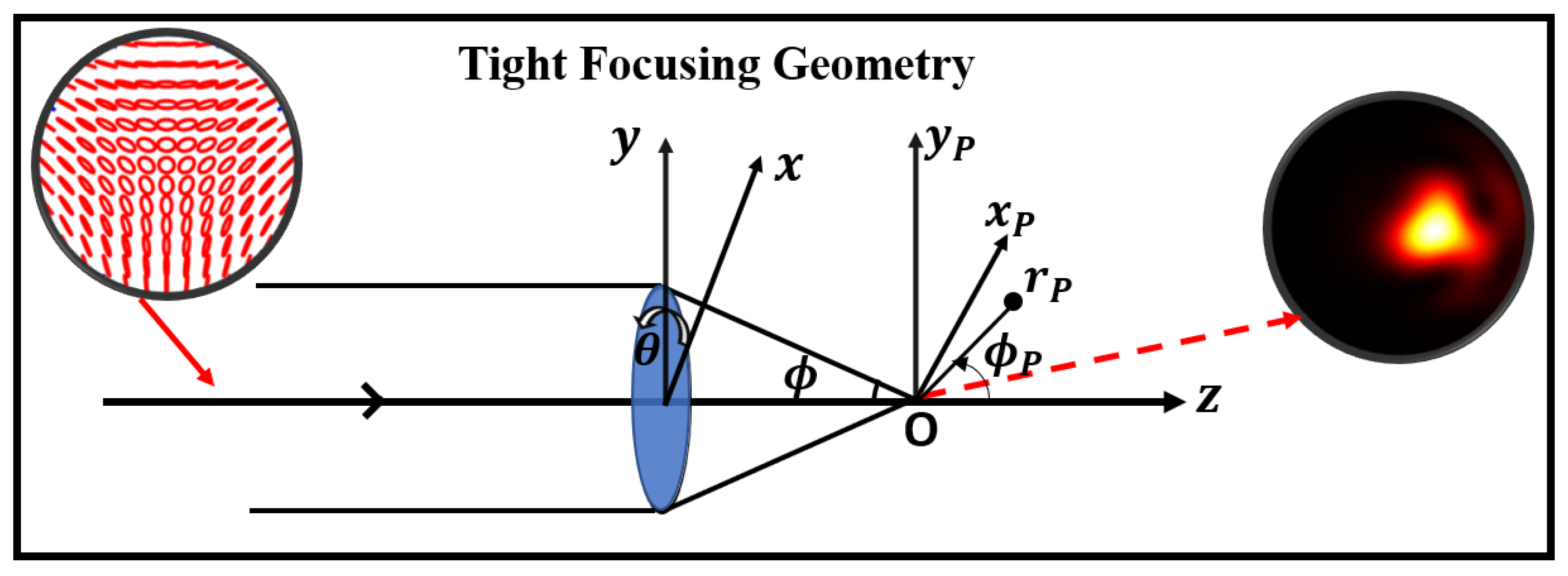
2. Theory of Tight Focusing for Circular Basis HyOPS Beams

The expression of HyOPS beams for paraxial optical fields, under circular polarization basis decomposition [31,54], can be written as,
E ( ρ , θ ) = E 0 e Γ 2 ρ 2 [ B 1 ρ m e i m θ e ^ L + B 2 ρ n e i n θ e ^ R ] ,
where e ^ L and e ^ R are left and right circular unit basis vectors, respectively. In Equation (1), the integers m, n are the topological charges of the phase vortex beams with amplitude scaling factors B 1 and B 2 , respectively, θ is azimuthal angle. E 0 is the amplitude of the beam, ρ = sin ϕ / sin ϕ m a x is the radial distance of a point from the center, normalized by the radius (a) of the lens. The truncation parameter is given by Γ = a / w , where w is the beam waist. It measures the beam’s fraction inside the lens’s physical aperture. For a bright C-point either m or n is zero and m n . So far, most studies concentrated on this type of beam [54,56]. Recently tight focusing of spatially varying optical fields embedded with polarization singularities such as bright C-points [83], dark C-points [32,84] and V-points [85] have been studied. The superposition described by Equation (1) can be realized by the Mach–Zehnder type interference, where the two arms carry the right circular and left circularly polarized beams, respectively. The bright HyOPS beams can be generated from Equation (1) by putting either of l 1 or l 2 as zero. For a dark C-point, both l 1 and l 2 are non-zero and | l 1 | | l 2 | . For realizing bright and dark HyOPS beams we consider A = B in Equation (1). By putting B 1 = 0 ( B 2 = 0 ) in the Equation (1) a right (left) circularly polarized phase singular beam can be realized. For realizing right and left circularly polarized plane beam the parameters n and m in the Equation (1) can be set to 0.
Introducing the conic angle ϕ , the term E 0 e Γ 2 ρ 2 in Equation (1) can be written as
E 0 e Γ 2 ρ 2 = E 0 e ( Γ 2 sin 2 ϕ / sin 2 ϕ m a x ) = E 2 ( ϕ ) ,
where ϕ is the focusing angle and ϕ m a x is the maximum angle of convergence as depicted in Figure 1. The numerical aperture of an optical system is given by N A = n 0 sin ϕ m a x , where n 0 is the refractive index of the focal region. The condition of aberration-free is an idealistic situation and the aberration-free condition is much stronger than the aplanatic condition, as the aplanatic condition is only free for all orders of spherical aberration, third-order coma, and third-order astigmatism. Aberration-free is sufficient and clearer because it says explicitly that the wavefront error of primary coma is embedded onto an ideal converging spherical wavefront without considering other effects. In the literature, aberration-free and aplanatic conditions are considered together [10,53]. For an optical system shown in Figure 1, the electric field components in the focal region of an aberration-free aplanatic lens are given by [10,53]
E ( u , v ) = ( i A / λ ) 0 ϕ m a x 0 2 π E 2 ( ϕ ) P ( ϕ , θ ) A 2 ( ϕ ) × e ( i k W ( ρ , θ ) ) × e ( i v sin ϕ m a x sin ϕ c o s ( θ θ P ) ) × e ( i u sin 2 ϕ m a x c o s ϕ ) sin θ d ϕ d θ ,
where A is linked to the optical system parameters and λ is the wavelength of light in the medium with refractive index ( n 0 ) in the focal region. Any point in the observation plane can be defined by the coordinates as P( r P , ϕ P , θ P ), where r P (radius vector connecting the point P with the origin of the coordinate system) and ϕ P are given by x P 2 + y P 2 , and arctan ( y P / x P ) , respectively. The azimuthal angle in the observation plane is given by θ P . In Equation (3), W ( ρ , θ ) corresponds to primary coma aberration. The primary coma aberration function is given by W ( ρ , θ ) = A c ρ 3 c o s θ [53,86], where A c is the comatic aberration coefficient in units of wavelength. P ( ϕ , θ ) denotes polarization distribution at the exit pupil and A 2 ( ϕ ) is the apodization factor.
The combined effect of the apodization and the intensity distribution of the beam (or the truncation parameter) play an important role in the focal plane beam shaping. To study the role of apodization in a tight-focusing optical system we must choose an appropriate form for the apodization function. We consider anodization A 2 ( ϕ ) = c o s q ϕ , so that q = 1 2 corresponds to the perfect aplanatic case [10,87,88]. The value q = 0 corresponds to the case of a constant angular variation, and for the higher values of q, the apodization drops faster with the focusing angle ( ϕ ). The real microscope objectives exhibit an anodization condition [89,90,91] that occurs from the Fresnel reflections at the surfaces of the optical elements. The effect of aberrations and apodization on the performance of coherent optical systems has been studied in the past [92,93,94]. The role of the intensity distribution of the input beam has been investigated in the literature [95]. Focus correction in an apodized system with spherical aberration has been investigated by Bernal et al. [96]. Recently Naresh et al. have shown the effect of a parabolic apodizer on improving the imaging of optical systems with coma and astigmatism aberration [97]. The apodization can be intuitively thought of as a circular aperture that can be considered as the first zone of a diffractive zone plate in which the focal length has a dependence on the zone diameter. There are also studies available on the focal length shift from the Gaussian focus due to the presence of helical phase distribution [98]. Polarization singularities are superposition of phase singularities and the size of dark cores (radial intensity distributions) of singularities depends on the index. These facts may play a role in the focal shift. However, our main discussion is on the tight focusing of HyOPS beams with fixed truncation parameters in the presence of primary coma.
The polarization distribution of the input field can be expressed as
P ( ϕ , θ ) = a 1 ( c o s ϕ c o s 2 θ + sin 2 θ ) + b 1 ( c o s ϕ sin θ c o s θ sin θ c o s θ ) a 1 ( c o s ϕ sin θ c o s θ sin θ c o s θ ) + b 1 ( c o s ϕ sin 2 θ + c o s 2 θ ) a 1 sin ϕ c o s θ b 1 sin ϕ sin θ ,
where a 1 and b 1 are the strengths of the x and y components of the input field, respectively. Optical coordinates at the observation plane or focal plane ( x P y P -plane) are defined as
u = k r P c o s θ P sin 2 ϕ m a x ,                     v = k r P sin θ P sin ϕ m a x ,
where k = 2 π / λ is the propagation vector. The parameters u and v are the dimensionless normalized parameters as described by Equation (5).
In this article, we study the tight focusing of generic star-type and lemon-type bright and dark HyOPS beams in the presence of primary coma. The left-handed lemon-type bright HyOPS beam can be realized from Equation (1) by putting m = 0 , and n = + 1 , respectively. For generating a right-handed lemon-type bright HyOPS beam we consider m = 1 , and n = 0 in the Equation (1). Similarly, a right-handed star type and a left-handed star type bright HyOPS beams can be realized from Equation (1) by putting ( m = 1 , n = 0 ) and ( m = 0 , n = 1 ), respectively. A left-handed and right-handed lemon-type dark HyOPS beams can be realized from Equation (1) by putting ( m = 1 , n = 2 ) and ( m = 2 , n = 1 ), respectively. For generating left-handed and right-handed star-type dark HyOPS beams we consider ( m = 1 , n = 2 ) and ( m = 2 , n = 1 ) in Equation (1). Focal plane intensity distributions of these eight different HyOPS beams are calculated by using Equation (3). Tight focusing of circularly polarized plane beams and the circularly polarized phase singular beams can be done by using Equation (3). The simulation results obtained from Equation (3) can be compared with the results presented in the [53] for the validation of our simulation and results. The parameter ϕ in our article is similar to parameter θ in the reference [53] and vice versa.

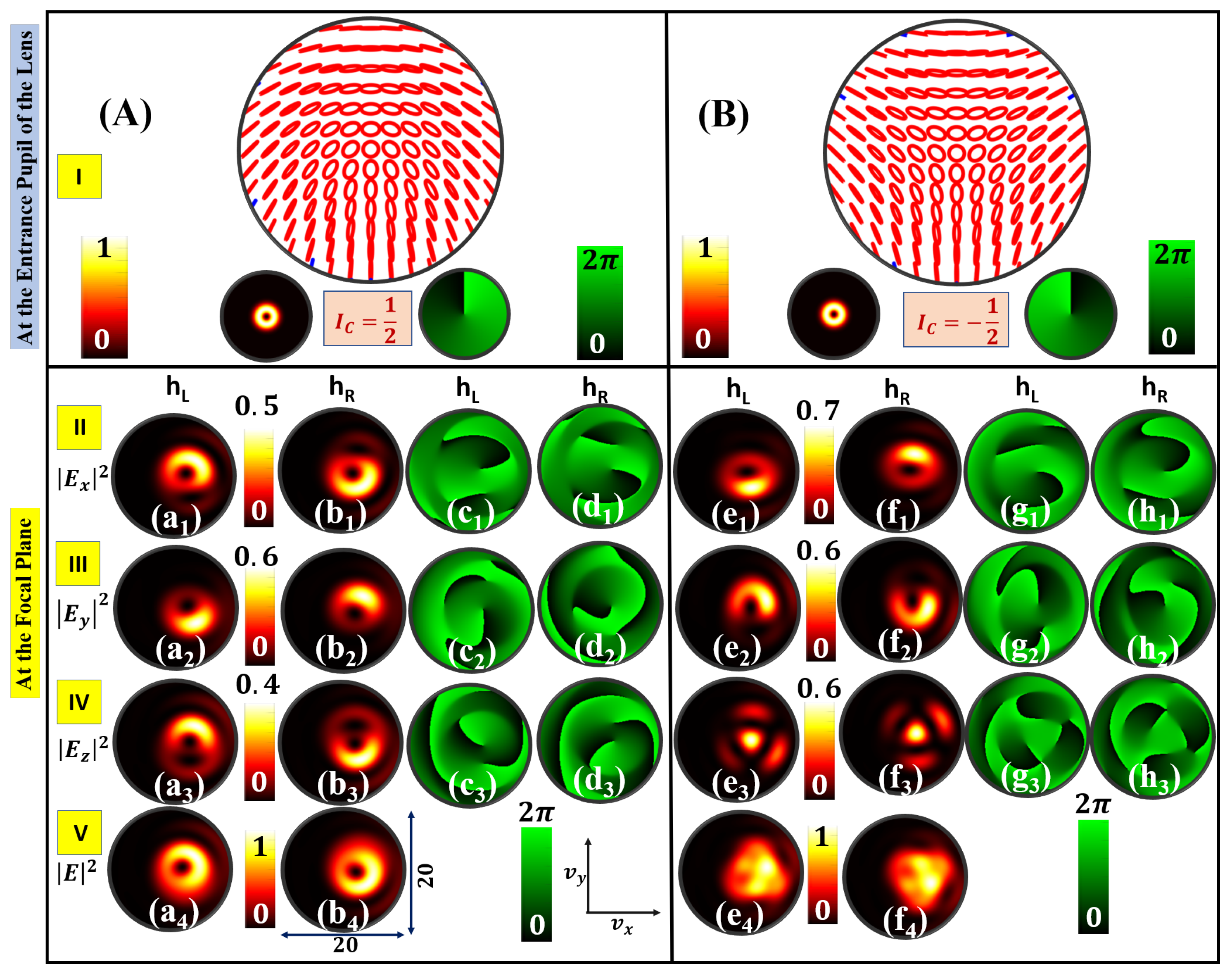
3. Intensity Landscapes of Circular Basis HyOPS Beams

Various parameters such as polarization distribution, total intensity distribution, and S 12 Stokes field phase distribution of bright and dark generic HyOPS beams at the entrance pupil of the lens are numerically evaluated using Equation (1). Debye-Wolf integration (Equation (3)) is used to compute the focal plane transverse and longitudinal components of the input HyOPS beams for NA equal to 0.95 . The focal plane field distributions are plotted in the normalized coordinates ( u , v ). All the simulation results presented in the paper are for u = 0 and 10 v 10 . We consider wavelength λ = 633 nm for all the computations. At the entrance pupil of the lens, the normalized Stokes parameters are computed by using transverse components of the HyOPS beams. Further, these normalized Stokes parameters are used to compute polarization parameters such as azimuth and ellipticity distributions. The azimuth and ellipticity distributions are used to demonstrate the polarization distributions of various HyOPS beams. Polarization, normalized intensity, and S 12 Stokes field phase distributions of input HyOPS beams are depicted in row I of Figure 2, Figure 3, Figure 4, Figure 5, Figure 6 and Figure 7. The intensity distributions of the bright HyOPS beams, as shown in Figure 2, Figure 3 and Figure 4, at the entrance pupil of the lens corresponds to the Gaussian distribution. The intensity distributions of the dark HyOPS beams, as shown in Figure 5, Figure 6 and Figure 7, at the entrance pupil of the lens corresponds to the Laguerre-Gaussian (LG) distribution. In all the figures, Figure 2, Figure 3, Figure 4, Figure 5, Figure 6 and Figure 7, the focal plane intensity distributions of transverse (x and y) and longitudinal (z) components are depicted in row II, row III, and row IV, respectively. In each case, the total intensity distribution is presented in row V. A HyOPS beam can be either left ( h L ) or right ( h R ) helicity [57,58]. For each HyOPS beam, the intensity and phase distributions corresponding to left and right helicity are shown in the left and right columns, respectively. For an aberration-free optical system, the focal plane intensity and phase distributions corresponding to bright lemon and star-type HyOPS beams are depicted in Figure 2. In Figure 2, column I and column II correspond to the intensity distributions of left and right-handed lemon singularities, respectively, and the corresponding component phase distributions are depicted in column III and column IV, respectively. The right side of Figure 2 shows the intensity and phase distributions corresponding to bright left and right-handed star-type HyOPS beams. In a tight focusing system, a HyOPS beam and its index inverted field show completely different intensity distributions at the focal plane in terms of shape and symmetry. Even for the same polarization singularity index the focal plane intensity and phase distributions are found to be dependent on helicity and intensity of the HyOPS beams.
Next, we study the effect of primary coma on the focal plane intensity and phase distributions for HyOPS beams as shown in Figure 2 for an optical system with NA 0.95 . When the strength of the primary coma is A c = 0.50 , the focal plane intensity and phase distributions corresponding to bright lemon and star-type HyOPS beams are shown in Figure 3. When the strength of the primary coma is A c = 0.75 , the focal plane intensity and phase distributions for bright lemon and star-type HyOPS beams are shown in Figure 4. From Figure 3 and Figure 4, it can be seen that the presence of primary coma in the optical system distorted the focal plane intensity distributions for both positive and negative index HyOPS beams. It is found that the presence of primary coma aberration in the focusing system produces a positional shift of the high-intensity lobes and a reduction of the intensity on one side of the center. As the strength of the primary coma increases, the focal plane intensity distributions shift more and more toward the right from the initial position. In the case of HyOPS beams, the focal plane intensity distribution undergoes rotation, as the helicity of the HyOPS beams is inverted, in addition to shifting in the presence of coma aberration. In all three cases, the focal plane field components are found to be embedded with phase vortices of charge ± 1 . The appearance of phase vortices in the individual field components may be due to the superposition of polarization components of the electric field.
To generalize our study, we consider another class of HyOPS beams, known as dark HyOPS beams. First, we consider tight focusing of dark lemon and star-type HyOPS beams in the absence of primary coma, and the corresponding results are shown in Figure 5. Row I of Figure 5 depicts polarization, intensity, and S 12 Stokes field phase distributions. In Figure 5, the focal plane intensity distributions corresponding to transverse (x and y component) and longitudinal (z-component) of the dark lemon and star-type HyOPS beams are shown in row II, row III, and row IV, respectively. The total intensity distribution is presented in row V. In Figure 5, columns I and II correspond to focal plane component intensity distributions of left and right-handed dark lemon-type HyOPS beams, respectively. The phase distribution corresponding to each component is depicted in columns III and IV, respectively. The focal plane intensity and phase distributions of dark star-type HyOPS beams are shown in columns V to VIII. Similar to bright HyOPS beams, all three focal plane field components of the dark HyOPS beams are found to be embedded with phase vortices of charge ± 1 . The effect of primary coma on the focal plane intensity and phase distributions of dark HyOPS beams for two different values of strength of primary coma are presented in Figure 6 and Figure 7. When the strength of the primary coma is A c = 0.50 , the focal plane intensity and phase distributions corresponding to dark lemon and star-type HyOPS beams are shown in Figure 6. Figure 7 shows the focal plane intensity and phase distributions for dark lemon and star-type HyOPS beams for A c = 0.75 . Similar to bright HyOPS beams, the presence of primary coma aberration shows a positional shift of the high-intensity lobes and a reduction of the intensity on one side of the center. As the strength of the primary coma increases, the focal plane intensity distributions shift more and more toward the right from the initial position. In addition to shifting the focal plane intensity and phase patterns also undergo helicity-dependent rotation in the case of tight focusing of HyOPS beams, which is not happening in the case of tight focusing of scalar vortices [53,86]. Note that in all the figures the focal plane component intensity distributions are normalized by the maximum value of the total intensity distribution.

4. Conclusions

In conclusion, we study the focal plane intensity and phase distributions of bright and dark circular basis HyOPS beams of I C = ± 1 2 for a high numerical aperture (NA = 0.95) system in the presence of a primary coma. It is shown that as the strength of the primary coma increases, the focal plane intensity as well as phase distributions shifted more and more toward the right from the initial position. The presence of primary coma aberration in the focusing system results in a positional shift of the high-intensity peaks, and a reduction of the intensity on one side of the center. For both positive and negative indexed bright and dark HyOPS beams, the focal plane intensity distribution undergoes rotation, as the helicity of the HyOPS beams is inverted, in addition to shifting.

Author Contributions

Conceptualization, S.K.P.; methodology, S.K.P.; formal analysis, S.K.P. and P.S.; investigation, S.K.P. and P.S.; data curation, S.K.P.; writing—original draft preparation, S.K.P.; writing—review and editing, S.K.P., R.K.S. and P.S.; visualization, S.K.P.; supervision, S.K.P. and P.S.; project administration, S.K.P. All authors have read and agreed to the published version of the manuscript.

Funding

R.K. Singh acknowledges the Council of Scientific and Industrial Research, India, for a research grant (80(0092)/20/EMR-II).

Institutional Review Board Statement

Not applicable.

Informed Consent Statement

Not applicable.

Data Availability Statement

The data that support the findings of this study are available from the corresponding author upon reasonable request.

Conflicts of Interest

The authors declare no conflicts of interest.

Abbreviations

The following abbreviations are used in this manuscript:
NA       numerical aperture
PSFpoint spread function
SOPstate of polarization
PSPoincaré sphere
HyOPShybrid order Poincaré sphere
HOPShigher order Poincaré sphere
OAMorbital angular momentum
RCPright circular polarization
LCPleft circular polarization
LGLaguerre Gaussian

References

  1. Linfoot, E.H.; Wolf, E. Diffraction Images in Systems with an Annular Aperture. Proc. Phys. Soc. Lond. B 1953, 66, 145–149. [Google Scholar] [CrossRef]
  2. Welford, W.T. Use of Annular Apertures to Increase Focal Depth. J. Opt. Soc. Am. 1960, 50, 749–753. [Google Scholar] [CrossRef]
  3. Singh, K.; Dhillon, H.S. Diffraction of Partially Coherent Light by an Aberration-Free Annular Aperture. J. Opt. Soc. Am. 1969, 59, 395–401. [Google Scholar] [CrossRef]
  4. Slepian, D. Analytic Solution of Two Apodization Problems. J. Opt. Soc. Am. 1965, 55, 1110–1115. [Google Scholar] [CrossRef]
  5. Stamnes, J.J. Focusing of two-dimensional waves. J. Opt. Soc. Am. 1981, 71, 15–31. [Google Scholar] [CrossRef]
  6. Belland, P.; Crenn, J.P. Changes in the characteristics of a Gaussian beam weakly diffracted by a circular aperture. Appl. Opt. 1982, 21, 522–527. [Google Scholar] [CrossRef]
  7. Duan, K.; Lü, B. Nonparaxial analysis of far-field properties of Gaussian beams diffracted at a circular aperture. Opt. Express 2003, 11, 1474–1480. [Google Scholar] [CrossRef]
  8. Hao, B.; Burch, J.; Leger, J. Smallest flattop focus by polarization engineering. Appl. Opt. 2008, 47, 2931–2940. [Google Scholar] [CrossRef]
  9. Wolf, E. Electromagnetic Diffraction in Optical Systems. I. An Integral Representation of the Image Field. Proc. R. Soc. Lond. Ser. A 1959, 253, 349–357. [Google Scholar]
  10. Richards, B.; Wolf, E. Electromagnetic diffraction in optical systems, II. Structure of the image field in an aplanatic system. Proc. R. Soc. Lond. A Math. Phys. Eng. Sci. 1959, 253, 358–379. [Google Scholar]
  11. Yoshida, A.; Asakura, T. Electromagnetic field in the focal plane of a coherent beam from a wide-angular annular-aperture system. Optik (Stuttgart) 1974, 40, 322–331. [Google Scholar]
  12. Yoshida, A.; Asakura, T. Electromagnetic field near the focus of Gaussian beams. Optik (Stuttgart) 1974, 41, 281–292. [Google Scholar]
  13. Sheppard, C.J.R.; Matthews, H.J. Imaging in high-aperture optical systems. J. Opt. Soc. Am. A 1987, 4, 1354–1360. [Google Scholar] [CrossRef]
  14. Kant, R. An Analytical Solution of Vector Diffraction for Focusing Optical Systems. J. Mod. Opt. 1993, 40, 337–347. [Google Scholar] [CrossRef]
  15. Sheppard, C.J.R. High-aperture beams. J. Opt. Soc. Am. A 2001, 18, 1579–1587. [Google Scholar] [CrossRef]
  16. Chon, J.W.M.; Gan, X.; Gu, M. Splitting of the focal spot of a high numerical-aperture objective in free space. Appl. Phys. Lett. 2002, 81, 1576–1578. [Google Scholar] [CrossRef]
  17. Niziev, V.G.; Nesterov, A.V. Influence of beam polarization on laser cutting efficiency. J. Phys. D Appl. Phys. 1999, 32, 1455–1461. [Google Scholar] [CrossRef]
  18. Salamin, Y.I.; Keitel, C.H. Electron Acceleration by a Tightly Focused Laser Beam. Phys. Rev. Lett. 2002, 88, 095005. [Google Scholar] [CrossRef]
  19. Dorn, R.; Quabis, S.; Leuchs, G. Sharper Focus for a Radially Polarized Light Beam. Phys. Rev. Lett. 2003, 91, 233901. [Google Scholar] [CrossRef] [PubMed]
  20. Davidson, N.; Bokor, N. High-numerical-aperture focusing of radially polarized doughnut beams with a parabolic mirror and a flat diffractive lens. Opt. Lett. 2004, 29, 1318–1320. [Google Scholar] [CrossRef] [PubMed]
  21. Quabis, S.; Dorn, R.; Eberler, M.; Glöckl, O.; Leuchs, G. Focusing light to a tighter spot. Opt. Commun. 2000, 179, 1–7. [Google Scholar] [CrossRef]
  22. Ferrari, J.A.; Dultz, W.; Schmitzer, H.; Frins, E. Achromatic wavefront forming with space-variant polarizers: Application to phase singularities and light focusing. Phys. Rev. A 2007, 76, 053815. [Google Scholar] [CrossRef]
  23. Gupta, D.N.; Kant, N.; Kim, D.E.; Suk, H. Electron acceleration to GeV energy by a radially polarized laser. Phys. Lett. A 2007, 368, 402–407. [Google Scholar] [CrossRef]
  24. Youngworth, K.S.; Brown, T.G. Focusing of high numerical aperture cylindrical-vector beams. Opt. Express 2000, 7, 77–87. [Google Scholar] [CrossRef]
  25. Zhang, W.; Liu, S.; Li, P.; Jiao, X.; Zhao, J. Controlling the polarization singularities of the focused azimuthally polarized beams. Opt. Express 2013, 21, 974–983. [Google Scholar] [CrossRef]
  26. Schoonover, R.W.; Visser, T.D. Polarization singularities of focused, radially polarized fields. Opt. Express 2006, 14, 5733–5745. [Google Scholar] [CrossRef]
  27. Dennis, M.R. Fermionic out-of-plane structure of polarization singularities. Opt. Lett. 2011, 36, 3765–3767. [Google Scholar] [CrossRef]
  28. Freund, I. Cones, spirals, and Möbius strips, in elliptically polarized light. Opt. Commun. 2005, 249, 7–22. [Google Scholar] [CrossRef]
  29. Bauer, T.; Neugebauer, M.; Leuchs, G.; Banzer, P. Optical Polarization Möbius Strips and Points of Purely Transverse Spin Density. Phys. Rev. Lett. 2016, 117, 013601. [Google Scholar] [CrossRef]
  30. Bauer, T.; Banzer, P.; Bouchard, F.; Orlov, S.; Marrucci, L.; Santamato, E.; Boyd, R.W.; Karimi, E.; Leuchs, G. Multi-twist polarization ribbon topologies in highly-confined optical fields. New J. Phys. 2019, 21, 053020. [Google Scholar] [CrossRef]
  31. Bauer, T.; Banzer, P.; Karimi, E.; Orlov, S.; Rubano, A.; Marrucci, L.; Santamato, E.; Boyd, R.W.; Leuchs, G. Observation of optical polarization Möbius strips. Science 2015, 347, 964–966. [Google Scholar] [CrossRef] [PubMed]
  32. Pal, S.K.; Somers, L.; Singh, R.K.; Senthilkumaran, P.; Arie, A. Focused polarization ellipse field singularities: Interaction of spin-orbital angular momentum and the formation of optical Möbius strips. Phys. Scr. 2023, 98, 055507. [Google Scholar] [CrossRef]
  33. Goldstein, D.H. Polarized Light; CRC Press: Boca Raton, FL, USA, 2011. [Google Scholar]
  34. Born, M.; Wolf, E. Principles of Optics; Cambridge University Press: Cambridge, UK, 2002. [Google Scholar]
  35. Poincaré, H. Mathematical Theory of Light: Mathematical Physics Course; Carre, G., Ed.; Carrè: Paris, France, 1889; Volume 1. [Google Scholar]
  36. Milione, G.; Sztul, H.I.; Nolan, D.A.; Alfano, R.R. Higher-Order Poincaré Sphere, Stokes Parameters, and the Angular Momentum of Light. Phys. Rev. Lett. 2011, 107, 053601. [Google Scholar] [CrossRef] [PubMed]
  37. Cardano, F.; Karimi, E.; Slussarenko, S.; Marrucci, L.; de Lisio, C.; Santamato, E. Polarization pattern of vector vortex beams generated by q-plates with different topological charges. Appl. Opt. 2012, 51, C1–C6. [Google Scholar] [CrossRef]
  38. Holleczek, A.; Aiello, A.; Gabriel, C.; Marquardt, C.; Leuchs, G. Classical and quantum properties of cylindrically polarized states of light. Opt. Express 2011, 19, 9714–9736. [Google Scholar] [CrossRef] [PubMed]
  39. Liu, Z.; Liu, Y.; Ke, Y.; Liu, Y.; Shu, W.; Luo, H.; Wen, S. Generation of arbitrary vector vortex beams on hybrid-order Poincaré sphere. Photonics Res. 2017, 5, 15–21. [Google Scholar] [CrossRef]
  40. Yi, X.; Liu, Y.; Ling, X.; Zhou, X.; Ke, Y.; Luo, H.; Wen, S.; Fan, D. Hybrid-order Poincaré sphere. Phys. Rev. A 2015, 91, 023801. [Google Scholar] [CrossRef]
  41. Zhang, Y.H.; Chen, P.; Ge, S.J.; Wei, T.; Tang, J.; Hu, W.; Lu, Y.Q. Spin-controlled massive channels of hybrid-order Poincaré sphere beams. Appl. Phys. Lett. 2020, 117, 081101. [Google Scholar] [CrossRef]
  42. Malacara, D. Optical Shop Testing; Wiley Publication: New York, NY, USA, 2007. [Google Scholar]
  43. Smith, W.J. Modern Optical Engineering; McGraw-Hill Publication: New York, NY, USA, 2000. [Google Scholar]
  44. Visser, T.D.; Wiersma, S.H. Spherical aberration and the electromagnetic field in high-aperture systems. J. Opt. Soc. Am. A 1991, 8, 1404–1410. [Google Scholar] [CrossRef]
  45. Visser, T.D.; Wiersma, S.H. Diffraction of converging electromagnetic waves. J. Opt. Soc. Am. A 1992, 9, 2034–2047. [Google Scholar] [CrossRef]
  46. Kant, R. An Analytical Solution of Vector Diffraction for Focusing Optical Systems with Seidel Aberrations. J. Mod. Opt. 1993, 40, 2293–2310. [Google Scholar] [CrossRef]
  47. Kant, R. An Analytical Method of Vector Diffraction for Focusing Optical Systems with Seidel Aberrations II: Astigmatism and Coma. J. Mod. Opt. 1995, 42, 299–320. [Google Scholar] [CrossRef]
  48. Sheppard, C.; Gu, M. Imaging by a High Aperture Optical System. J. Mod. Opt. 1993, 40, 1631–1651. [Google Scholar] [CrossRef]
  49. Wang, Y.; Yong, K.; Chen, D.; Zhang, R. Influence of spherical aberration on the tightly focusing characteristics of vector vortex beams. Opt. Express 2023, 31, 28229–28240. [Google Scholar] [CrossRef] [PubMed]
  50. Dai, X.; Li, Y.; Liu, L. Tight focusing properties of hybrid-order Poincaré sphere beams. Opt. Commun. 2018, 426, 46–53. [Google Scholar] [CrossRef]
  51. Lerman, G.M.; Stern, L.; Levy, U. Generation and tight focusing of hybridly polarized vector beams. Opt. Express 2010, 18, 27650–27657. [Google Scholar] [CrossRef] [PubMed]
  52. Hu, K.; Chen, Z.; Pu, J. Tight focusing properties of hybridly polarized vector beams. J. Opt. Soc. Am. A 2012, 29, 1099–1104. [Google Scholar] [CrossRef]
  53. Singh, R.K.; Senthilkumaran, P.; Singh, K. Structure of a tightly focused vortex beam in the presence of primary coma. Opt. Commun. 2009, 282, 1501–1510. [Google Scholar] [CrossRef]
  54. Dennis, M.R. Polarization singularities in paraxial vector fields: Morphology and statistics. Opt. Commun. 2002, 213, 201–221. [Google Scholar] [CrossRef]
  55. Berry, M.V. The electric and magnetic polarization singularities of paraxial waves. J. Opt. A Pure Appl. Opt. 2004, 6, 475–481. [Google Scholar] [CrossRef]
  56. Freund, I. Polarization singularity indices in Gaussian laser beams. Opt. Commun. 2002, 201, 251–270. [Google Scholar] [CrossRef]
  57. Pal, S.K.; Senthilkumaran, P. Index polarity inversion by helicity inversion in Stokes vortices. Appl. Phys. Lett. 2020, 117, 201101. [Google Scholar] [CrossRef]
  58. Pal, S.K.; Arora, G.; Ruchi; Senthilkumaran, P. Handedness control in polarization lattice fields by using spiral phase filters. Appl. Phys. Lett. 2021, 119, 221106. [Google Scholar] [CrossRef]
  59. Zhan, Q. Cylindrical vector beams: From mathematical concepts to applications. Adv. Opt. Photon. 2009, 1, 1–57. [Google Scholar] [CrossRef]
  60. Senthilkumaran, P. Singularities in Physics and Engineering; Number 2053–2563; IOP Publishing: Bristol, UK, 2018. [Google Scholar]
  61. Freund, I.; Mokhun, A.I.; Soskin, M.S.; Angelsky, O.V.; Mokhun, I.I. Stokes singularity relations. Opt. Lett. 2002, 27, 545–547. [Google Scholar] [CrossRef]
  62. Samlan, C.T.; Suna, R.R.; Naik, D.N.; Viswanathan, N.K. Spin-orbit beams for optical chirality measurement. Appl. Phys. Lett. 2018, 112, 031101. [Google Scholar] [CrossRef]
  63. Han, W.; Cheng, W.; Zhan, Q. Flattop focusing with full Poincaré beams under low numerical aperture illumination. Opt. Lett. 2011, 36, 1605–1607. [Google Scholar] [CrossRef]
  64. Xue, Y.; Wang, Y.; Zhou, S.; Chen, H.; Rui, G.; Gu, B.; Zhan, Q. Focus shaping and optical manipulation using highly focused second-order full Poincaré beam. J. Opt. Soc. Am. A 2018, 35, 953–958. [Google Scholar] [CrossRef]
  65. Salamin, Y.I. Acceleration in vacuum of bare nuclei by tightly focused radially polarized laser light. Opt. Lett. 2007, 32, 3462–3464. [Google Scholar] [CrossRef]
  66. Dai, L.; Li, J.X.; Zang, W.P.; Tian, J.G. Vacuum electron acceleration driven by a tightly focused radially polarized Gaussian beam. Opt. Express 2011, 19, 9303–9308. [Google Scholar] [CrossRef]
  67. Zheng, Y.; Cai, X.; Zhao, X.; Wang, W. Acceleration of electrons by tightly focused azimuthally polarized ultrashort pulses in a vacuum. Opt. Express 2022, 30, 1627–1640. [Google Scholar] [CrossRef] [PubMed]
  68. Abouraddy, A.F.; Toussaint, K.C. Three-Dimensional Polarization Control in Microscopy. Phys. Rev. Lett. 2006, 96, 153901. [Google Scholar] [CrossRef] [PubMed]
  69. Cipparrone, G.; Ricardez-Vargas, I.; Pagliusi, P.; Provenzano, C. Polarization gradient: Exploring an original route for optical trapping and manipulation. Opt. Express 2010, 18, 6008–6013. [Google Scholar] [CrossRef] [PubMed]
  70. Kozawa, Y.; Sato, S. Optical trapping of micrometer-sized dielectric particles by cylindrical vector beams. Opt. Express 2010, 18, 10828–10833. [Google Scholar] [CrossRef]
  71. Zhan, Q. Trapping metallic Rayleigh particles with radial polarization. Opt. Express 2004, 12, 3377–3382. [Google Scholar] [CrossRef] [PubMed]
  72. de Sande, J.C.G.; Santarsiero, M.; Piquero, G. Spirally polarized beams for polarimetry measurements of deterministic and homogeneous samples. Opt. Lasers Eng. 2017, 91, 97–105. [Google Scholar] [CrossRef]
  73. de Sande, J.C.G.; Piquero, G.; Santarsiero, M. Polarimetry with azimuthally polarized light. Opt. Commun. 2018, 410, 961–965. [Google Scholar] [CrossRef]
  74. Perez-Garcia, B.; Hernández-Aranda, R.I.; López-Mariscal, C.; Gutiérrez-Vega, J.C. Morphological transformation of generalized spirally polarized beams by anisotropic media and its experimental characterization. Opt. Express 2019, 27, 33412–33426. [Google Scholar] [CrossRef]
  75. Milione, G.; Lavery, M.P.J.; Huang, H.; Ren, Y.; Xie, G.; Nguyen, T.A.; Karimi, E.; Marrucci, L.; Nolan, D.A.; Alfano, R.R.; et al. 4 × 20 Gbit/s mode division multiplexing over free space using vector modes and a q-plate mode (de)multiplexer. Opt. Lett. 2015, 40, 1980–1983. [Google Scholar] [CrossRef]
  76. Gabriel, C.; Aiello, A.; Zhong, W.; Euser, T.G.; Joly, N.Y.; Banzer, P.; Förtsch, M.; Elser, D.; Andersen, U.L.; Marquardt, C.; et al. Entangling Different Degrees of Freedom by Quadrature Squeezing Cylindrically Polarized Modes. Phys. Rev. Lett. 2011, 106, 060502. [Google Scholar] [CrossRef]
  77. Davis, J.A.; Nowak, M.D. Selective edge enhancement of images with an acousto-optic light modulator. Appl. Opt. 2002, 41, 4835–4839. [Google Scholar] [CrossRef] [PubMed]
  78. Pal, S.K.; Gangwar, K.K.; Senthilkumaran, P. Tailoring polarization singularity lattices by phase engineering of three-beam interference. Optik 2022, 255, 168680. [Google Scholar] [CrossRef]
  79. Pal, S.K.; Manisha; Senthilkumaran, P. Phase engineering in overlapping lattices of polarization singularities. J. Opt. Soc. Am. B 2023, 40, 1830–1836. [Google Scholar] [CrossRef]
  80. Meier, M.; Romano, V.; Feurer, T. Material processing with pulsed radially and azimuthally polarized laser radiation. Appl. Phys. A 2007, 86, 329–334. [Google Scholar] [CrossRef]
  81. Shen, Y.; Martínez, E.C.; Rosales-Guzmán, C. Generation of Optical Skyrmions with Tunable Topological Textures. ACS Photonics 2022, 9, 296–303. [Google Scholar] [CrossRef]
  82. Xu, L.; Zhang, Y.; Lang, S.; Wang, H.; Hu, H.; Wang, J.; Gong, Y. Structured Illumination Microscopy Based on Asymmetric Three-beam Interference. J. Innov. Opt. Health Sci. 2021, 14, 2050027. [Google Scholar] [CrossRef]
  83. Pal, S.K.; Singh, R.K.; Senthilkumaran, P. Focal intensity landscapes of tightly focused spatially varying bright ellipse fields. J. Opt. 2022, 24, 044013. [Google Scholar] [CrossRef]
  84. Pal, S.K. Tight focusing of orthogonal C-point polarization states. Optik 2023, 274, 170535. [Google Scholar] [CrossRef]
  85. Otte, E.; Tekce, K.; Lamping, S.; Ravoo, B.J.; Denz, C. Polarization nano-tomography of tightly focused light landscapes by self-assembled monolayers. Nat. Commun. 2019, 10, 4308. [Google Scholar] [CrossRef]
  86. Singh, R.K.; Senthilkumaran, P.; Singh, K. Effect of primary coma on the focusing of a Laguerre–Gaussian beam by a high numerical aperture system; vectorial diffraction theory. J. Opt. A Pure Appl. Opt. 2008, 10, 075008. [Google Scholar] [CrossRef]
  87. Sheppard, C.J.R.; Larkin, K.G. Effect of numerical aperture on interference fringe spacing. Appl. Opt. 1995, 34, 4731–4734. [Google Scholar] [CrossRef]
  88. Sheppard, C.J.R. Orthogonal aberration functions for high-aperture optical systems. J. Opt. Soc. Am. A 2004, 21, 832–838. [Google Scholar] [CrossRef] [PubMed]
  89. Matthews, H.J.; Hamilton, D.H.; Sheppard, C. Aberration Measurement by Confocal Interferometry. J. Mod. Opt. 1989, 36, 233–250. [Google Scholar] [CrossRef]
  90. Kubota, H.; Inoué, S. Diffraction Images in the Polarizing Microscope. J. Opt. Soc. Am. 1959, 49, 191–198. [Google Scholar] [CrossRef] [PubMed]
  91. Zhou, H.; Gu, M.; Sheppard, C. Investigation of Aberration Measurement in Confocal Microscopy. J. Mod. Opt. 1995, 42, 627–638. [Google Scholar] [CrossRef]
  92. Mills, J.P.; Thompson, B.J. Effect of aberrations and apodization on the performance of coherent optical systems. I. The amplitude impulse response. J. Opt. Soc. Am. A 1986, 3, 694–703. [Google Scholar] [CrossRef]
  93. Mills, J.P.; Thompson, B.J. Effect of aberrations and apodization on the performance of coherent optical systems. II. Imaging. J. Opt. Soc. Am. A 1986, 3, 704–716. [Google Scholar] [CrossRef]
  94. Allred, D.B.; Mills, J.P. Effect of aberrations and apodization on the performance of coherent optical systems. 3: The near field. Appl. Opt. 1989, 28, 673–681. [Google Scholar] [CrossRef]
  95. Mahajan, V.N. Uniform versus Gaussian beams: A comparison of the effects of diffraction, obscuration, and aberrations. J. Opt. Soc. Am. A 1986, 3, 470–485. [Google Scholar] [CrossRef]
  96. Bernal-Molina, P.; Castejón-Mochón, J.F.; Bradley, A.; López-Gil, N. Focus correction in an apodized system with spherical aberration. J. Opt. Soc. Am. A 2015, 32, 1556–1563. [Google Scholar] [CrossRef]
  97. Reddy, A.N.K.; Dev, V.; Pal, V.; Ganeev, R.A. The Effect of a Parabolic Apodizer on Improving the Imaging of Optical Systems with Coma and Astigmatism Aberrations. Photonics 2024, 11, 14. [Google Scholar] [CrossRef]
  98. Zhang, S.; Bai, Z.; Li, J.; Lyu, Y.; Man, Z.; Xing, F.; Ge, X.; Fu, S. Tunable focal shift induced by polarization and phase shaping. Optik 2019, 199, 162788. [Google Scholar] [CrossRef]
Figure 1. Geometric configuration for tight focusing of a right-handed bright star-type HyOPS beam in the presence of primary coma.
Photonics 11 00098 g001
Figure 2. Bright HyOPS beams with (A) I C = 1 2 ; and (B) I C = 1 2 are tightly focused. Focal plane component intensities are shown in row II ( | E x | 2 ), row III ( | E y | 2 ) and row IV ( | E z | 2 ), respectively. Normalized total intensity ( | E | 2 ) distributions are shown in row V. Left and right helicity are denoted as h L and h R , respectively. Phase distributions of the constituent field components are shown on the right side of the intensity distributions.
Photonics 11 00098 g002
Figure 3. Bright HyOPS beams with (A) I C = 1 2 ; and (B) I C = 1 2 , as shown in Figure 2, are tightly focused in the presence of primary coma with primary coma strength A c = 0.50 .
Photonics 11 00098 g003
Figure 4. Bright HyOPS beams with (A) I C = 1 2 ; and (B) I C = 1 2 , as shown in Figure 2, are tightly focused in the presence of primary coma with primary coma strength A c = 0.75 .
Photonics 11 00098 g004
Figure 5. Dark HyOPS beams with (A) I C = 1 2 ; and (B) I C = 1 2 are tightly focused. Focal plane component intensities are shown in row II ( | E x | 2 ), row III ( | E y | 2 ), and row IV ( | E z | 2 ), respectively. Normalized total intensity ( | E | 2 ) distributions are shown in row V. Left and right helicity are denoted as h L and h R , respectively. Phase distributions of the constituent field components are shown on the right side of the intensity distributions.
Photonics 11 00098 g005
Figure 6. Dark HyOPS beams with (A) I C = 1 2 ; and (B) I C = 1 2 , as shown in Figure 5, are tightly focused in the presence of primary coma with primary coma strength A c = 0.50 .
Photonics 11 00098 g006
Figure 7. Dark HyOPS beams with (A) I C = 1 2 ; and (B) I C = 1 2 , as shown in Figure 5, are tightly focused in the presence of primary coma with primary coma strength A c = 0.75 .
Photonics 11 00098 g007
Disclaimer/Publisher’s Note: The statements, opinions and data contained in all publications are solely those of the individual author(s) and contributor(s) and not of MDPI and/or the editor(s). MDPI and/or the editor(s) disclaim responsibility for any injury to people or property resulting from any ideas, methods, instructions or products referred to in the content.

