Article

The Propagation Characteristics of Circular Airy Beams with Propagational Fractional-Order Optical Vortices

1
Sino-German College of Intelligent Manufacturing, Shenzhen Technology University, Shenzhen 518118, China
2
College of Big Data and Internet, Shenzhen Technology University, Shenzhen 518118, China
*
Authors to whom correspondence should be addressed.
Photonics 2024, 11(1), 64; https://doi.org/10.3390/photonics11010064
Submission received: 23 November 2023 / Revised: 31 December 2023 / Accepted: 4 January 2024 / Published: 7 January 2024

Abstract

:
We investigate the propagation properties of circular Airy beams (CABs) with propagational fractional-order optical vortices (OVs). The superposition of the phase singularity and polarization singularity from a vortex vector beam (VVB) plays a significant role in creating a propagational fractional vortex beam. Propagational fractional vortex beams can be considered as a superposition of left and right circularly polarized vortex beams with different integer topological charges (TCs). We study the propagation characteristics of two kinds of propagational fractional vortex CABs, and the results show that both of the two kinds of beams can stably propagate in free space, and they exhibit an “abruptly auto-focusing” property and “self-healing” property during the propagation. The intensity distribution of the first kind of propagational fractional vortex CAB has an odd number of petals (2m + 1), while the second kind of beam has a crescent-shaped intensity distribution. The influence of turbulence on the beam propagation through atmosphere under different turbulence strengths is also numerically studied in this paper. A fractional vortex CAB with an initial radius r0 = 10 mm can retain its shape after propagating 20 m when the atmospheric refractive-index structure constant C N 2 = 0.2 × 1 0 12 m 2 / 3 . Our results are expected to broaden the application of CABs.

1. Introduction

In 1989, Coullet et al. found vortex solutions for the Maxwell–Bloch equations and presented the concept of optical vortices (OVs) [1]. Vortex beams are of interest because of their helical phase wavefronts characterized by the factor exp ( i m φ ) , where m and φ represent the topological charge (TC) and azimuthal angle, respectively. In 1992, Allen et al. pointed out that a vortex beam can induce orbital angular momentum (OAM) equivalent to m ( is the reduced Planck constant) per photon [2]. Following Allen et al.’s study in 1992 [2], vortex beams have greatly contributed to fundamental and applied research in optics, including spin angular momentum (SAM) and OAM conversion [3,4], rotational Doppler shift [5,6,7], optical manipulation [8,9,10], optical imaging [11,12], and optical communication [13,14,15,16]. Most of the studies on vortex beams were carried out in a framework where the TC is an integer. In fact, the TC can also be a non-integer, i.e., fractional, and a vortex beam with a fractional TC is called a fractional vortex beam [17]. Unlike the integer-order vortex beam, the fractional vortex beam has discontinuous phase along the phase step and notched intensity distribution [17]. Because of their unique physical properties, fractional vortex beams have important applications in complex micro-particle manipulation [18], expanding communication capacity [19], anisotropic edge enhancement of image [20], and quantum entanglement [21]. However, most studies have shown that fractional vortex beams cannot propagate stably in free space [22,23,24]. Only recently, Weng et al. demonstrated that propagational fractional vortex beams can be generated by superimposing the phase and polarization singularities of vortex vector beams (VVBs) induced by vortex phase and vortex polarization [25,26].
On the other hand, the circular Airy beam (CAB), a circularly symmetric beam with an Airy profile, is also of interest because of its “abruptly autofocusing” property [27,28,29,30,31,32]. A CAB can maintain a low and constant intensity profile directly before the target, while at the target, the intensity suddenly increases by several orders of magnitude. Taking advantage of this “abruptly autofocusing” property, CABs can deliver high-energy pulses in transparent samples without causing damage [33], which is attractive in biomedical therapeutics [34], transparent material processing, and nonlinear optical processes [33]. The behavior of a CAB with OVs is very different from that of a CAB without OVs, since during propagation, the OVs can translate, rotate, or be annihilated in the background beam due to the intensity gradient and phase gradient [30,32,35,36,37]. Lu X. H. et al. found that OVs can greatly enhance the “abruptly autofocusing” property of a CAB, and an on-axis OV can give a CAB a hollow intensity distribution [30]. Deng D. M. et al. found that the focal length and the intensity of the optical focus can be modified by appropriately selecting the distribution factor, the TC, and the size of the incident beams [36]. In 2022, we found that a left circularly polarized CAB imposed with an on-axis OV will give rise to both left and right circularly polarized components with OV in the crystal [38]. What is the influence of fractional-order OV on a CAB, and does the CAB retain its “non-diffracting”, “self-healing”, and “abruptly autofocusing” properties? To the best of our knowledge, none of these issues have been reported. In this paper, the propagation characteristics of two kinds of propagational fractional vortex CABs, in free space and turbulent atmosphere, are numerically studied and discussed. Our study results are expected to broaden the application of CABs.

2. Theory and Model

According to Weng’s results [25], there are two kinds of fractional vortex beams that can stably maintain their amplitudes and vortex phases in free space. They can be expressed as follows [25]:
E mf 1 = exp ± i 0.5 φ cos [ ( m + 0.5 ) φ + β ] sin [ ( m + 0.5 ) φ + β ] ,
E mf 2 = exp i ( l + 0.5 ) φ cos ( ± 0.5 φ + β ) sin ( ± 0.5 φ + β ) ,
where φ is the azimuthal angle, β is the polarization direction of the vector beam, and m and l are integers. The first fractional vortex beam, described in Equation (1), possesses an OV with a TC of ±0.5 and a polarization state of the (m + 0.5)-order vector beam. The second kind of fractional vortex beam, described in Equation (2), has an OV with a variable TC of l + 0.5 but a constant polarization state, namely, of the 0.5-order vector beam. In principle, a fractional-order polarization vortex cannot induce OAM. Therefore, the vortex beams described in Equations (1) and (2) naturally carry fractional OAM arising from the OVs, with TCs of 0.5 and l + 0.5, respectively. Without loss of generality, we let β be equal to 0 and “ ± ” be “ + ”. It should be noted that the two kinds of beams depicted by Equations (1) and (2) possess a homogeneous amplitude distribution.
Using Euler’s formula, we can easily rewrite Equations (1) and (2) into the following form:
E mf 1 = 2 2 exp [ i ( m + 1 ) φ ] | R + 2 2 exp ( i m φ ) | L ,
E mf 2 = 2 2 exp [ i ( l + 1 ) φ ] | R + 2 2 exp ( i l φ ) | L .
where | R = 2 2 ( e x i e y ) and | L 2 2 ( e x + i e y ) denote the left and right circularly polarized modes; e x and e y , respectively, are the unit vectors in the cartesian coordinate system. Equations (3) and (4) clearly show that the two kinds of beams can be generated by superposition of left and right circularly polarized vortex beams with different integer TCs. From Equation (3), we can see that the first kind of beam can be regarded as a superposition of an (m + 1)-order right circularly polarized vortex beam and a (−m)-order left circularly polarized vortex beam. Notice that the TCs of the left circularly polarized and right circularly polarized components have opposite signs but similar values, and it can be expected that the first kind of beam has similar characteristics to an m-order vector beam. The second kind of beam consists of an l + 1 -order right circularly polarized vortex beam and an l-order left circularly polarized vortex beam (see Equation (4)). Unlike the first kind of beam, the TCs of the left circularly polarized and right circularly polarized components have the same signs and similar values. In particular, when l = m = 0 , the two kinds of beams are exactly the same beam.
The amplitude distribution of a CAB in the input plane z = 0 can be expressed as [27]:
l 0 ( r , z = 0 ) = C · A i ( r 0 r w ) exp ( a r 0 r w ) ,
where C is a constant, A i represents the Airy function, r 0 is the initial radius of the CAB, w is the radial scale coefficient, and a is the decay parameter. Correspondingly, the two kinds of propagational fractional vortex CABs in the input plane can be written as
E 1,2 r , z = 0 = l 0 r , z = 0 E mf 1 , m f 2 .
Since both kinds of propagational fractional vortex CABs are essentially vector beams, they can be generated in the laboratory by two orthogonal left and right circularly polarized vortices [39]. We can adopt the method of generating a vector beam proposed by Zhao et al. to obtain fractional order vortex CABs [39]. Zhao et al. propose an efficient and robust method to generate tunable vector beams by employing a phase-only spatial light modulator (SLM) [39]. Note that since we are generating CABs with OVs, the phase to generate the CABs needs to be loaded into the SLM at the same time as the vortex phase.
Assuming that the beam propagates in the positive direction along the z-axis, the electric field of beam at any plane can be calculated using the angular spectrum formulas as
E r , z = I F F T F F T E r , z = 0 exp i k 0 2 k x 2 k y 2 z ,
where F F T is the Fourier transform (FT) and I F F T is the inverse FT, r is the transverse coordinate, k 0 = 2 π λ is the wave number, and k x and k y are transverse wave numbers. From Equation (7), we can see that the electric field of the beam at any plane can be obtained as long as the Fourier spectrum of the E ( r , z = 0 ) is known. While the closed-form approximation of the Fourier spectrum of a CAB is given by the appropriate plane-wave angular spectral representation of the beam [31], there is no analytic expression for the FT of a CAB with OVs. Therefore, we use the discrete Fourier transform (DFT) to obtain the Fourier spectrum of the initial beam by means of the fast Fourier transform (FFT) algorithm.

3. Results and Discussion

In our numerical study, the beam parameters are given as follows: r0 = 1 mm, w = 50 µm, a = 0.05, and the wavelength λ = 632.8 nm.
In order to highlight the characteristics of propagational fractional vortex CABs, we first study the propagation characteristics of an m-order vector CAB with an OV having a TC of 0.5. The electric field of the beam in the input plane can be expressed as follows:
E ( r , φ , z = 0 ) = l 0 ( r , z = 0 ) · exp ( i 0.5 φ ) cos ( m φ ) sin ( m φ ) .
Substituting Equation (8) into Equation (7), we can obtain the evolution of an m-order vector CAB with an OV having a TC of 0.5. The intensity distributions of the x-polarization component at different propagation distances are shown in Figure 1. As can be seen from Figure 1, the beam has a pattern of 2 m petals on the input plane, but it becomes notched and cannot propagate stably. These results are consistent with the conclusions of previous studies on ordinary fractional vortex beams [17]. It should be pointed out that the beam has a homogeneous polarization distribution when m = 0 , and Equation (8) depicts a scalar CAB with an OV having a TC of 0.5.

3.1. The First Kind of Propagational Fractional Vortex CAB

According to Equations (1) and (5), the electric field of the first kind of propagational fractional vortex CAB in the input plane can be expressed as
E 1 r , φ , z = 0 = l 0 r , z = 0 · exp ( i 0.5 φ ) cos [ ( m + 0.5 ) φ ] sin [ ( m + 0.5 ) φ ] .
Substituting Equation (9) into Equation (7), we can obtain the evolution of the first kind of propagational fractional vortex CAB in free space. Since the polarization of the vector beam is inhomogeneous, we plot the intensity and phase distributions of the x-polarization component at different propagation distances for m = 0, 1, and 2, as shown in Figure 2, Figure 3, and Figure 4, respectively. From Figure 2, Figure 3 and Figure 4, it can be seen that the beam exhibits a 2m + 1 petal-like pattern, and the beam is able to propagate stably, which is quite different from the case shown in Figure 1. As mentioned above, the first kind of propagational fraction vortex CAB is in fact an (m + 0.5)-order vector beam with an OV having a TC of 0.5. Unlike m-order vector beams, which can be physically interpreted as combinations of left and right circularly polarized beams with a TC of ±m [25,39,40], the phase distribution of the first kind of propagational fractional vortex CABs is not binary. For comparison purposes, we also give the propagation characteristics of a 2-order vector CAB, as shown in Figure 5. It clearly shows that a 2-order vector beam has a 4-petal pattern, and it has a binary (white and black) phase distribution initially. The first kind of propagational fractional vortex CABs maintain their shape during the propagation, meaning that the fractional-order OV does not influence their “non-diffraction” property. Due to the “abruptly autofocusing” property, the size of the beam becomes increasingly smaller, while the intensity becomes increasingly stronger, before the focus (z = 224 mm). It can also be seen from Figure 2(d1), Figure 3(d1), and Figure 4(d1) that the distance from the maximum intensity to the center of the beam at the focal plane increases as the value of m increases. Comparing the pattern before and after the focus point, we can see that the spot pattern is rotated. To observe the steady propagation of the first kind of propagational fractional vortex CAB, we give an animation of the evolution of the beam for m = 2, as detailed in the Supplementary Materials.
In order to better characterize the “abruptly autofocusing” property of the beam, we assume that I 0 and I m are the maximum intensity in the initial plane and in any plane along the propagation, respectively, and that r m is the distance between the maximum intensity and the center of the beam. The “abruptly autofocusing” property can be investigated in terms of I m / I 0 and r m versus the propagation distance, z. The relationships of I m / I 0 and r m with z are shown in Figure 6. As can be seen from Figure 6a, the beam maintains a low and almost constant intensity before the focal plane (z = 224 mm), and its intensity suddenly increases by several tens of times at the focal point. From Figure 6b, it can be seen that the size of the strongest spot decreases with increasing propagation distance and reaches a minimum at the focal plane. Interestingly, the position of the focal plane does not change with the value of m, but the maximum intensity decreases with increasing value of m. The larger the value of m is, the smaller the maximum of I m / I 0 is, which is due to the fact that beams with a larger m have more bright spots. r m versus z in Figure 6b shows that the larger the value of m is, the larger r m is. This result is consistent with a normal-vortex CAB [30,36].
Another important property of the CAB is “self-healing”, and we further investigate whether the fractional vortex CAB also possesses this property. As an example, we study the “self-healing” property of the first kind of propagational fractional vortex CAB with m = 2. We block one of the main petals in the initial plane and propagate the resulting beam in free space. The evolution of the beam is shown in Figure 7. As a comparison, the corresponding unblocked beam propagation is also shown in Figure 7. As can be seen in Figure 7, the disappearing main petal regrows during propagation, after which the intensity pattern of the beam is almost identical to that of the unblocked beam. The result clearly shows that the first kind of propagational fractional vortex CAB possesses the “self-healing” property.

3.2. The Second Kind of Propagational Fractional Vortex CAB

The electric field of the second kind of propagational fractional vortex CAB can be represented as follows:
E 2 r , φ , z = 0 = l 0 r , z = 0 · exp [ i ( l + 0.5 ) φ ] cos ( 0.5 φ ) sin ( 0.5 φ ) .
Substituting Equation (10) into Equation (7), we can obtain the evolution of this kind of beam. We obtain the intensity distribution and phase distribution of the x-polarization component at different propagation distances for l = 1 and l = 2, respectively, as shown in Figure 8 and Figure 9. Also, we give an animation of the evolution of the beam for l = 2, as detailed in the Supplementary Materials. In the same way as the first kind of beam, the second kind of propagational fractional vortex CABs can maintain their shapes and propagate stably in free space. As can be seen in Figure 8 and Figure 9, all these beams have a crescent-shaped intensity distribution (having only 1 petal), which is due to the fact that these beams are 0.5-order vector beams with an OV having a TC of ( 2 l + 1 ) . The “abruptly autofocusing” property of the beam is as shown in Figure 10. Comparison of Figure 6 and Figure 10 reveals that the “abruptly autofocusing” properties of the two kinds of propagational vortex CABs are similar. The “abruptly autofocusing” effect takes place at z = 0.224 m and is independent of the TC value of l + 0.5. Figure 10 shows that the beam with the smaller TC value of l + 0.5 has a stronger “abruptly autofocusing” effect and a smaller size of focus spot.

4. Fractional Vortex CAB Propagation in Turbulent Atmospheres

The simulation of atmospherically distorted wavefronts is of importance in the context of studies of beam propagation through turbulent atmospheres. In the above study, the effect of turbulence on the beam is very weak due to the short propagation distance. In order to study the propagation characteristics of the beam in turbulent media, we enlarge the size of the beam by a factor of 10, i.e., r0 = 10 mm, w = 500 µm.
We use multiple phase-screens and the Fourier-transform algorithm to study the beam propagation in turbulent atmospheres [41,42]. In the multiple phase-screen model, the propagation distance L is split into N sub-distances Δ z i = z i z i 1 (i = 1…N), and the electric field at zi can be obtained as [42]
E ( r , z i ) = I F F T { F F T [ E ( r , z i 1 ) exp i φ ( x , y ) ) ] exp ( i k 0 2 k x 2 k y 2 Δ z i } .
φ ( x , y ) is the additional phase induced by turbulence (phase screen), which is given by [41]
φ ( x , y ) = I F F T [ h ( f x , f y ) Φ φ ( f x , f y ) ] ,
where h ( f x , f y ) is a complex random matrix, and f x and f x are spatial frequencies. Φ ϕ ( f x , f y ) is the power spectrum of the phase fluctuations. The Wiener power spectrum of the phase fluctuations in the Kolmogoroff atmosphere is given by [43]
Φ φ ( f x , f y ) = 0.023 R o 5 / 3 f 1 / 3 ,
where f is the spatial frequency. R 0 is an important parameter reflecting the intensity of atmospheric turbulence, which is determined by
R 0 0.185 λ C N 2 3 5 ,
where C N 2 is the atmospheric refractive-index structure constant.
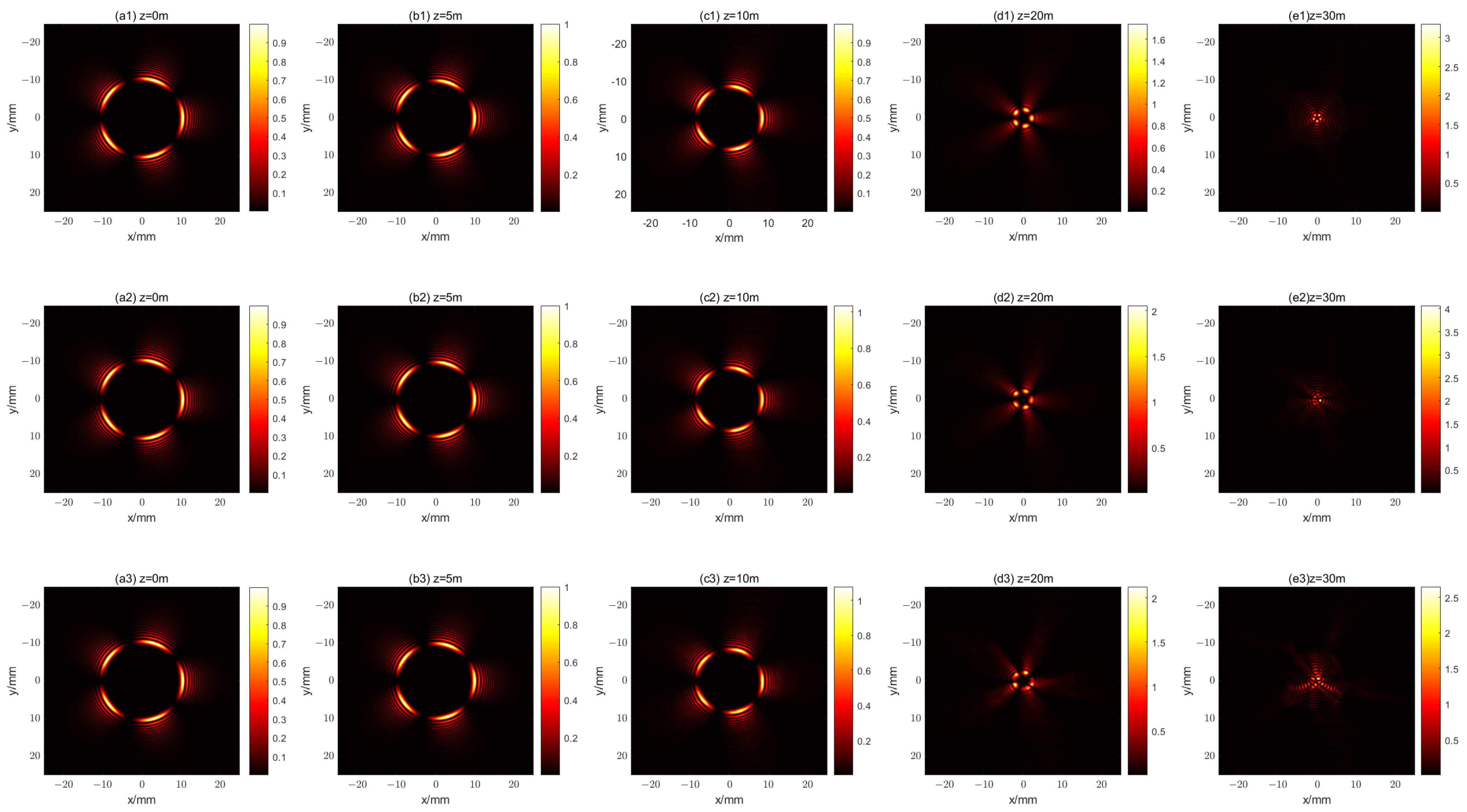
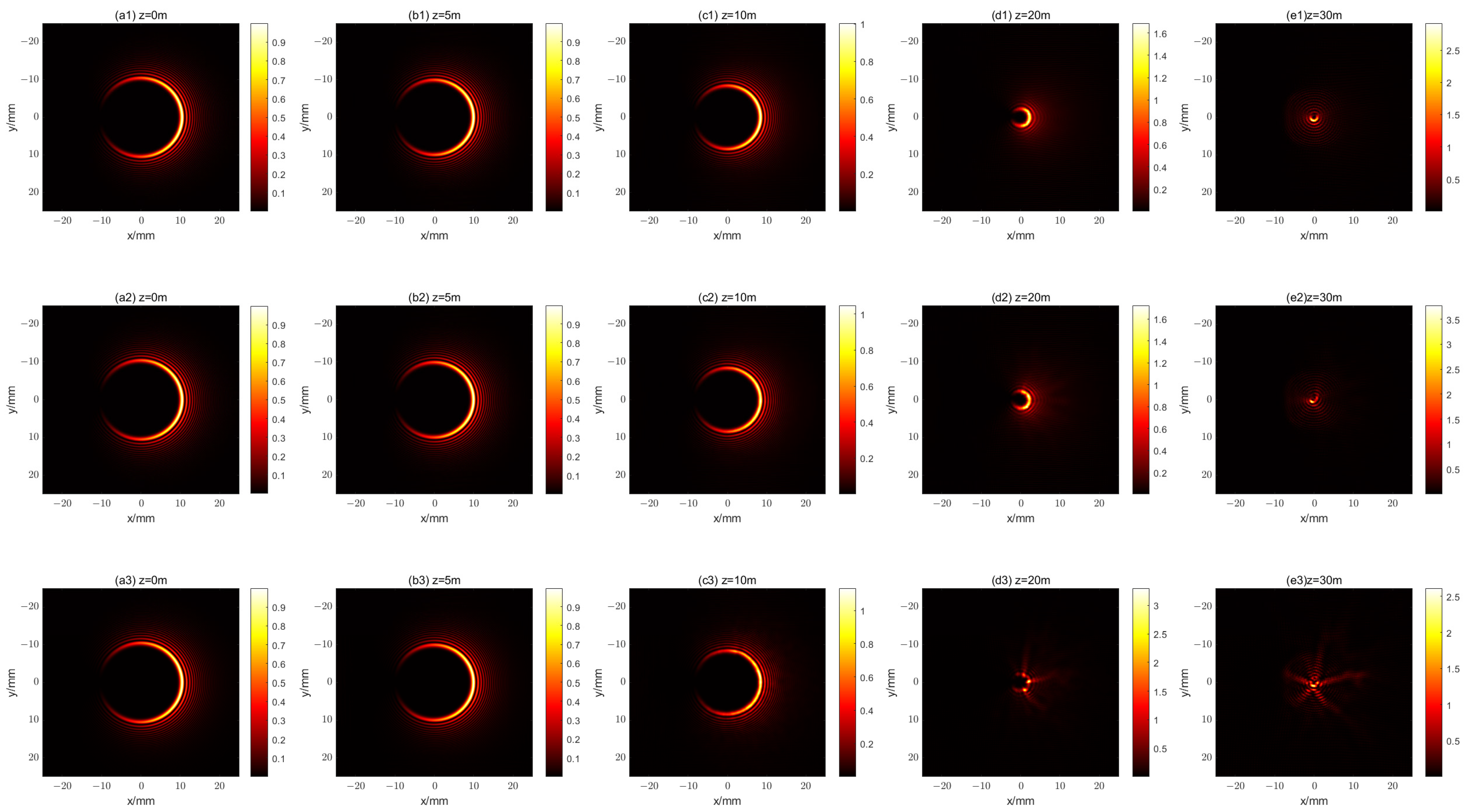
Employing Equations (11)–(14), we can obtain the propagation characteristics of the beam in a turbulent atmosphere. Figure 11 and Figure 12 give the propagations of the two kinds of beams for different values of C N 2 . As can be seen in Figure 10 and Figure 11, the beam is able to maintain its shape unaffected under weak turbulence ( C N 2 = 0.02 × 1 0 12   m 2 / 3 ). Figure 11 and Figure 12 also show that the beam retains its shape after propagating 20 m when C N 2 = 0.2 × 1 0 12   m m 2 / 3 , whereas the beam has already been deformed when C N 2 = 2 × 1 0 12   m 2 / 3 .

5. Conclusions

In conclusion, we have demonstrated the propagation properties of the two kinds of propagational fractional vortex CABs. The intensity distributions and phase distributions of the two kinds of beams at different propagation distances have been illustrated and analyzed. The two kinds of propagational fractional vortex CABs exhibit the “abruptly auto-focusing” property and “self-healing” property during the propagation, and they can stably propagate in free space. The two kinds of beams have similar “abruptly autofocusing” properties, where the focus length is independent of the value of the TC. In addition, the fractional-order OV does not influence the “non-diffraction” property of the CABs. Since these two beams belong to different orders of vector beams, the first kind of beam has an intensity distribution with an odd number of petals, while the second beam has a crescent-shaped intensity distribution. These findings are expected to support applications in optical micromanipulation. Due to the “self-healing” property, the blocked main petal grows back during propagation, and thereafter the pattern of the beam is almost identical to that of the unblocked beam. The influence of turbulence on the beam propagation through atmosphere under different turbulence strengths was also numerically studied. A fractional vortex CAB with an initial radius r0 = 10 mm can maintain its shape unaffected under weak turbulence ( C N 2 = 0.02 × 1 0 12   m 2 / 3 ). When the atmospheric refractive-index structure constant C N 2 = 0.2 × 1 0 12   m 2 / 3 , the beam can still retain its shape after propagating 20 m.

Supplementary Materials

The following supporting information can be downloaded at: https://www.mdpi.com/article/10.3390/photonics11010064/s1, Video S1: evolution of first fractional-order CAB.avi; Video S2: evolution of second fractional-order CAB.avi.

Author Contributions

Conceptualization, G.Z.; methodology, G.Z. and L.W.; software, Q.W.; formal analysis, G.Z. and T.H.; visualization, G.Z.; writing—original draft preparation, G.Z.; writing—review and editing, X.Z.; project administration, G.Z.; funding acquisition, G.Z. All authors have read and agreed to the published version of the manuscript.

Funding

This research was funded by the Shenzhen Science and Technology Programs (20220719141014001, 20220717104706001, and SZWD2021001) and the Natural Science Foundation of Top Talent of SZTU (20200211).

Institutional Review Board Statement

Not applicable.

Informed Consent Statement

Not applicable.

Data Availability Statement

Data underlying the results presented in this paper are not publicly available at this time but may be obtained from the authors upon reasonable request.

Conflicts of Interest

The authors declare no conflict of interest.

References

  1. Coullet, P.; Gil, L.; Rocca, F. Optical vortices. Opt. Commun. 1989, 73, 403–408. [Google Scholar] [CrossRef]
  2. Allen, L.; Beijersbergen, M.W.; Spreeuw, R.J.C.; Woerdman, J.P. Orbital angular momentum of light and the transformation of Laguerre-Gaussian laser modes. Phys. Rev. A 1992, 45, 8185–8189. [Google Scholar] [CrossRef] [PubMed]
  3. Devlin, R.C.; Ambrosio, A.; Rubin, N.A.; Mueller, J.P.B.; Capasso, F. Arbitrary spin-to–orbital angular momentum conversion of light. Science 2017, 358, 896–901. [Google Scholar] [CrossRef] [PubMed]
  4. Stav, T.; Faerman, A.; Maguid, E.; Oren, D.; Kleiner, V.; Hasman, E.; Segev, M. Quantum entanglement of the spin and orbital angular momentum of photons using metamaterials. Science 2018, 361, 1101–1104. [Google Scholar] [CrossRef] [PubMed]
  5. Courtial, J.; Robertson, D.A.; Dholakia, K.; Allen, L.; Padgett, M.J. Rotational Frequency Shift of a Light Beam. Phys. Rev. Lett. 1998, 81, 4828–4830. [Google Scholar] [CrossRef]
  6. Li, G.; Zentgraf, T.; Zhang, S. Rotational Doppler effect in nonlinear optics. Nat. Phys. 2016, 12, 736–740. [Google Scholar] [CrossRef]
  7. Lavery, M.P.J.; Speirits, F.C.; Barnett, S.M.; Padgett, M.J. Detection of a Spinning Object Using Light’s Orbital Angular Momentum. Science 2013, 341, 537–540. [Google Scholar] [CrossRef]
  8. Grier, D.G. A revolution in optical manipulation. Nature 2003, 424, 810–816. [Google Scholar] [CrossRef]
  9. He, H.; Friese, M.E.J.; Heckenberg, N.R.; Rubinsztein-Dunlop, H. Direct Observation of Transfer of Angular Momentum to Absorptive Particles from a Laser Beam with a Phase Singularity. Phys. Rev. Lett. 1995, 75, 826–829. [Google Scholar] [CrossRef]
  10. Simpson, N.B.; Dholakia, K.; Allen, L.; Padgett, M.J. Mechanical equivalence of spin and orbital angular momentum of light: An optical spanner. Opt. Lett. 1997, 22, 52–54. [Google Scholar] [CrossRef]
  11. Tamburini, F.; Anzolin, G.; Umbriaco, G.; Bianchini, A.; Barbieri, C. Overcoming the Rayleigh Criterion Limit with Optical Vortices. Phys. Rev. Lett. 2006, 97, 163903. [Google Scholar] [CrossRef] [PubMed]
  12. Gao, P.; Prunsche, B.; Zhou, L.; Nienhaus, K.; Nienhaus, G.U. Background suppression in fluorescence nanoscopy with stimulated emission double depletion. Nat. Photonics 2017, 11, 163–169. [Google Scholar] [CrossRef]
  13. Gibson, G.; Courtial, J.; Padgett, M.J.; Vasnetsov, M.; Pas’ko, V.; Barnett, S.M.; Franke-Arnold, S. Free-space information transfer using light beams carrying orbital angular momentum. Opt. Express 2004, 12, 5448–5456. [Google Scholar] [CrossRef] [PubMed]
  14. Wang, J.; Yang, J.-Y.; Fazal, I.M.; Ahmed, N.; Yan, Y.; Huang, H.; Ren, Y.; Yue, Y.; Dolinar, S.; Tur, M.; et al. Terabit free-space data transmission employing orbital angular momentum multiplexing. Nat. Photonics 2012, 6, 488–496. [Google Scholar] [CrossRef]
  15. Bozinovic, N.; Yue, Y.; Ren, Y.; Tur, M.; Kristensen, P.; Huang, H.; Willner, A.E.; Ramachandran, S. Terabit-Scale Orbital Angular Momentum Mode Division Multiplexing in Fibers. Science 2013, 340, 1545–1548. [Google Scholar] [CrossRef]
  16. Wang, X.-L.; Cai, X.-D.; Su, Z.-E.; Chen, M.-C.; Wu, D.; Li, L.; Liu, N.-L.; Lu, C.-Y.; Pan, J.-W. Quantum teleportation of multiple degrees of freedom of a single photon. Nature 2015, 518, 516–519. [Google Scholar] [CrossRef]
  17. Zhang, H.; Zeng, J.; Lu, X.; Wang, Z.; Zhao, C.; Cai, Y. Review on fractional vortex beam. Nanophotonics 2022, 11, 241–273. [Google Scholar] [CrossRef]
  18. Tao, S.H.; Yuan, X.C.; Lin, J.; Peng, X.; Niu, H.B. Fractional optical vortex beam induced rotation of particles. Opt. Express 2005, 13, 7726–7731. [Google Scholar] [CrossRef]
  19. Zhu, G.; Bai, Z.; Chen, J.; Huang, C.; Wu, L.; Fu, C.; Wang, Y. Ultra-dense perfect optical orbital angular momentum multiplexed holography. Opt. Express 2021, 29, 28452–28460. [Google Scholar] [CrossRef]
  20. Situ, G.; Pedrini, G.; Osten, W. Spiral phase filtering and orientation-selective edge detection/enhancement. J. Opt. Soc. Am. A 2009, 26, 1788–1797. [Google Scholar] [CrossRef]
  21. Oemrawsingh, S.S.R.; Ma, X.; Voigt, D.; Aiello, A.; Eliel, E.R.; ’t Hooft, G.W.; Woerdman, J.P. Experimental Demonstration of Fractional Orbital Angular Momentum Entanglement of Two Photons. Phys. Rev. Lett. 2005, 95, 240501. [Google Scholar] [CrossRef] [PubMed]
  22. Berry, M.V. Optical vortices evolving from helicoidal integer and fractional phase steps. J. Opt. A Pure Appl. Opt. 2004, 6, 259. [Google Scholar] [CrossRef]
  23. Gbur, G. Fractional vortex Hilbert’s Hotel. Optica 2016, 3, 222–225. [Google Scholar] [CrossRef]
  24. Leach, J.; Yao, E.; Padgett, M.J. Observation of the vortex structure of a non-integer vortex beam. New J. Phys. 2004, 6, 71. [Google Scholar] [CrossRef]
  25. Weng, X.; Miao, Y.; Wang, G.; Zhan, Q.; Dong, X.; Qu, J.; Gao, X.; Zhuang, S. Propagable Optical Vortices with Natural Noninteger Orbital Angular Momentum in Free Space. Adv. Photonics Res. 2023, 4, 2200094. [Google Scholar] [CrossRef]
  26. Weng, X.; Miao, Y.; Chen, Y.; Song, Q.; Liu, L.; He, J.; Liao, C.; Wang, Y.; Gao, X.; Qu, J.; et al. Physical Essence of Propagable Fractional-Strength Optical Vortices in Free Space. Adv. Photonics Res. 2023, 4, 2300152. [Google Scholar] [CrossRef]
  27. Efremidis, N.K.; Christodoulides, D.N. Abruptly autofocusing waves. Opt. Lett. 2010, 35, 4045–4047. [Google Scholar] [CrossRef]
  28. Papazoglou, D.G.; Efremidis, N.K.; Christodoulides, D.N.; Tzortzakis, S. Observation of abruptly autofocusing waves. Opt. Lett. 2011, 36, 1842–1844. [Google Scholar] [CrossRef]
  29. Liu, S.; Wang, M.; Li, P.; Zhang, P.; Zhao, J. Abrupt polarization transition of vector autofocusing Airy beams. Opt. Lett. 2013, 38, 2416–2418. [Google Scholar] [CrossRef]
  30. Jiang, Y.; Huang, K.; Lu, X. Propagation dynamics of abruptly autofocusing Airy beams with optical vortices. Opt. Express 2012, 20, 18579–18584. [Google Scholar] [CrossRef]
  31. Chremmos, I.; Zhang, P.; Prakash, J.; Efremidis, N.K.; Christodoulides, D.N.; Chen, Z. Fourier-space generation of abruptly autofocusing beams and optical bottle beams. Opt. Lett. 2011, 36, 3675–3677. [Google Scholar] [CrossRef] [PubMed]
  32. Davis, J.A.; Cottrell, D.M.; Sand, D. Abruptly autofocusing vortex beams. Opt. Express 2012, 20, 13302–13310. [Google Scholar] [CrossRef] [PubMed]
  33. Panagiotopoulos, P.; Papazoglou, D.G.; Couairon, A.; Tzortzakis, S. Sharply autofocused ring-Airy beams transforming into non-linear intense light bullets. Nat. Commun. 2013, 4, 2622. [Google Scholar] [CrossRef] [PubMed]
  34. Dasgupta, R.; Ahlawat, S.; Verma, R.S.; Gupta, P.K. Optical orientation and rotation of trapped red blood cells with Laguerre-Gaussian mode. Opt. Express 2011, 19, 7680–7688. [Google Scholar] [CrossRef] [PubMed]
  35. Rozas, D.; Law, C.T.; Swartzlander, G.A. Propagation dynamics of optical vortices. J. Opt. Soc. Am. B 1997, 14, 3054–3065. [Google Scholar] [CrossRef]
  36. Chen, B.; Chen, C.; Peng, X.; Peng, Y.; Zhou, M.; Deng, D. Propagation of sharply autofocused ring Airy Gaussian vortex beams. Opt. Express 2015, 23, 19288–19298. [Google Scholar] [CrossRef]
  37. Chen, G.; Huang, X.; Xu, C.; Huang, L.; Xie, J.; Deng, D. Propagation properties of autofocusing off-axis hollow vortex Gaussian beams in free space. Opt. Express 2019, 27, 6357–6369. [Google Scholar] [CrossRef]
  38. Zheng, G.; Wu, Q.; He, T.; Zhang, X. Propagation Characteristics of Circular Airy Vortex Beams in a Uniaxial Crystal along the Optical Axis. Micromachines 2022, 13, 1006. [Google Scholar] [CrossRef]
  39. Milione, G.; Lavery, M.P.J.; Huang, H.; Ren, Y.; Xie, G.; Nguyen, T.A.; Karimi, E.; Marrucci, L.; Nolan, D.A.; Alfano, R.R.; et al. 4 × 20 Gbit/s mode division multiplexing over free space using vector modes and a q-plate mode (de)multiplexer. Opt. Lett. 2015, 40, 1980–1983. [Google Scholar] [CrossRef]
  40. Miao, Y.; Weng, X.; Wang, Y.; Wang, L.; Wang, G.; Gao, X.; Zhuang, S. Parallel creation of propagable integer- and fractional-order vector vortex beams using mode extraction principle. Opt. Lett. 2022, 47, 3319–3322. [Google Scholar] [CrossRef]
  41. McGlamery, B.L. Restoration of Turbulence-Degraded Images. J. Opt. Soc. Am. 1967, 57, 293–297. [Google Scholar] [CrossRef]
  42. He, W.; Wu, J.; Yang, C.; Han, Y.; Xu, G. Numerical Simulation of Beam Propagation through Atmospheric Turbulence for Laser Radar; SPIE: Bellingham, WA, USA, 2008; Volume 6832. [Google Scholar]
  43. Roddier, N. Atmospheric wavefront simulation using Zernike polynomials. Opt. Eng. 1990, 29, 1174–1180. [Google Scholar] [CrossRef]
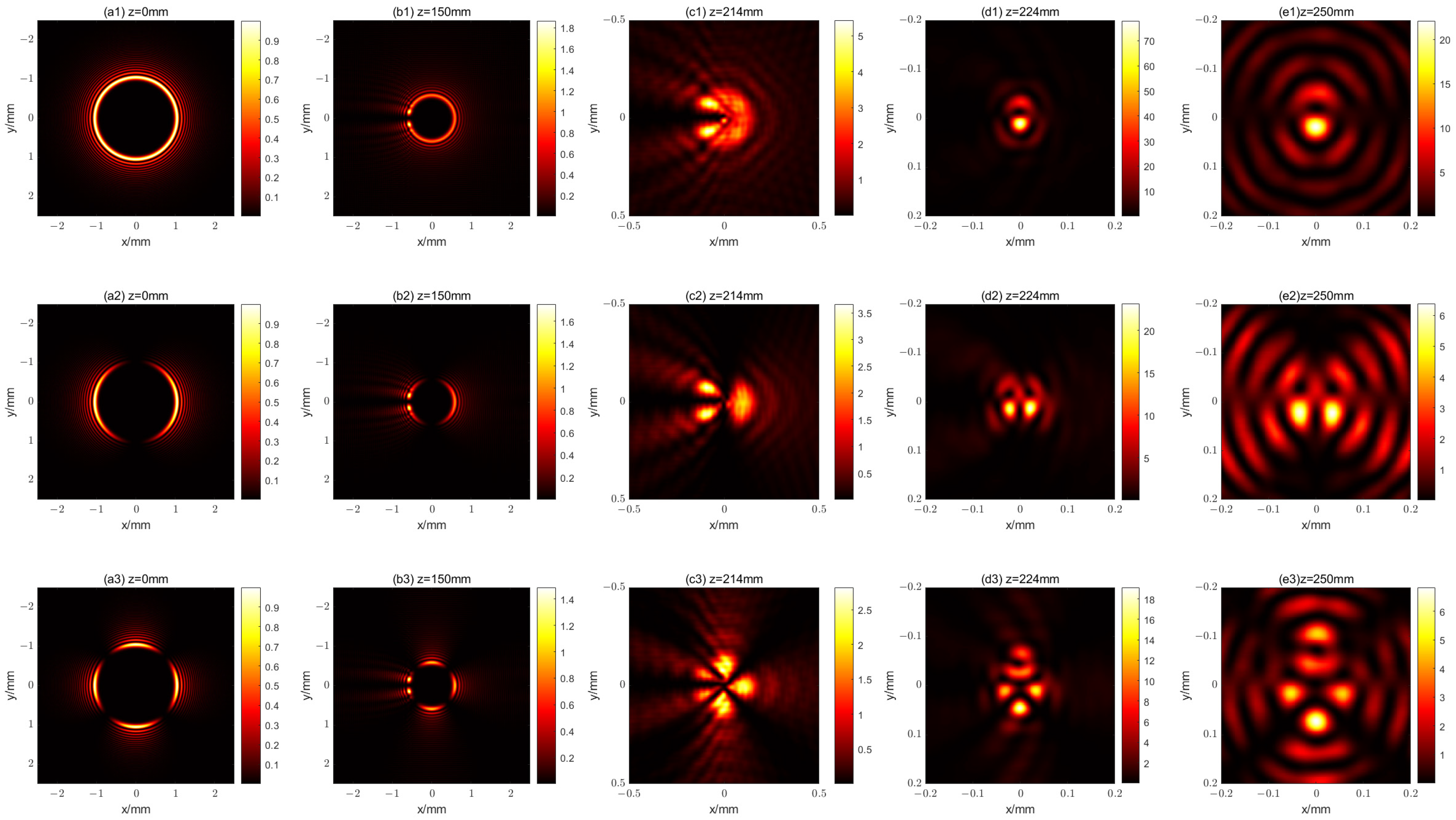
Figure 1. The intensity distribution of the x-polarization component of an m-order vector CAB with an OV having a TC of 0.5 at different distances. The first line (a1e1), the second line (a2e2), and the last line (a3e3) show the cases where m is 0, 1, and 2, respectively.
Photonics 11 00064 g001
Figure 2. The intensity and phase distributions of the x-polarization component of the first kind of propagational fractional vortex CAB with m = 0 at different distances. (a1e1) show the intensity distribution for z = 0 mm, 150 mm, 214 mm, 224 mm, and 250 mm, respectively; (a2e2) show the corresponding phase distribution.
Photonics 11 00064 g002
Figure 3. The intensity and phase distributions of the x-polarization component of the first kind of propagational fractional vortex CAB with m = 1 at different distances. (a1e1) show the intensity distribution for z = 0 mm, 150 mm, 214 mm, 224 mm, and 250 mm, respectively; (a2e2) show the corresponding phase distribution.
Photonics 11 00064 g003
Figure 4. The intensity and phase distributions of the x-polarization component of the first kind of propagational fractional vortex CAB with m = 2 at different distances. (a1e1) show the intensity distribution for z = 0 mm, 150 mm, 214 mm, 224 mm, and 250 mm, respectively; (a2e2) show the corresponding phase distribution.
Photonics 11 00064 g004
Figure 5. The intensity and phase distributions of the x-polarization component of a 2-order vector CAB at different distances. (a1e1) show the intensity distribution for z = 0 mm, 150 mm, 214 mm, 224 mm, and 250 mm, respectively; (a2e2) show the corresponding phase distribution.
Photonics 11 00064 g005
Figure 6. The “abruptly autofocusing” property of the first kind of propagational fractional vortex CAB. (a) shows I m / I 0 versus z; (b) shows r m versus z.
Photonics 11 00064 g006
Figure 7. The self-healing property of the first kind of propagational fractional vortex CAB with m = 2. (a1e1) and (a2e2) show the intensity distribution of the x-polarization component with and without blocking.
Photonics 11 00064 g007
Figure 8. The intensity and phase distributions of the x-polarization component of the second kind of propagational fractional vortex CAB with l = 1 at different distances. (a1e1) show the intensity distribution for z = 0 mm, 150 mm, 214 mm, 224 mm, and 250 mm, respectively; (a2e2) show the corresponding phase distribution.
Photonics 11 00064 g008
Figure 9. The intensity and phase distributions of the x-polarization component of the second kind of propagational fractional vortex CAB with l = 2 at different distances. (a1e1) show the intensity distribution for z = 0 mm, 150 mm, 214 mm, 224 mm, and 250 mm, respectively; (a2e2) show the corresponding phase distribution.
Photonics 11 00064 g009
Figure 10. The “abruptly autofocusing” property of the second kind of propagational fractional vortex CAB. (a) shows I m / I 0 versus z; (b) shows r m versus z.
Photonics 11 00064 g010
Figure 11. The intensity distribution of the x-polarization component of the first kind of propagational fractional vortex CAB with m = 2 at different distances. The first line (a1e1), the second line (a2e2), and the last line (a3e3) show the cases when C N 2 is 0.02 × 1 0 12   m 2 / 3 , 0.2 × 1 0 12   m 2 / 3 , and 2 × 1 0 12   m 2 / 3 , respectively.
Photonics 11 00064 g011
Figure 12. The intensity distribution of the x-polarization component of the second kind of fractional vortex CAB with l = 2 at different distances. The first line (a1e1), the second line (a2e2), and the last line (a3e3) show the cases where C N 2 is 0.02 × 1 0 12   m 2 / 3 , 0.2 × 1 0 12   m 2 / 3 , and 2 × 1 0 12   m 2 / 3 , respectively.
Photonics 11 00064 g012
Disclaimer/Publisher’s Note: The statements, opinions and data contained in all publications are solely those of the individual author(s) and contributor(s) and not of MDPI and/or the editor(s). MDPI and/or the editor(s) disclaim responsibility for any injury to people or property resulting from any ideas, methods, instructions or products referred to in the content.