Performance Analysis of a Single Light Source Bidirectional Visible Light Communication Reverse Reflection Link

Abstract
:1. Introduction
- (1)
- We established a single light source duplex visible light communication system model and derived the effective incidence angle of the light source that can reach the receiving end of the uplink and the maximum travel distance of the reverse reflector through geometric optics.
- (2)
- In order to further verify the reliability of the formula, we establish a simulation model of the uplink of single-light source duplex visible light communication. Through simulation verification and formula derivation, we obtain the influence of the changes in system parameters on the effective incidence angle of the light source and the maximum travel distance of the reverse reflector.
- (3)
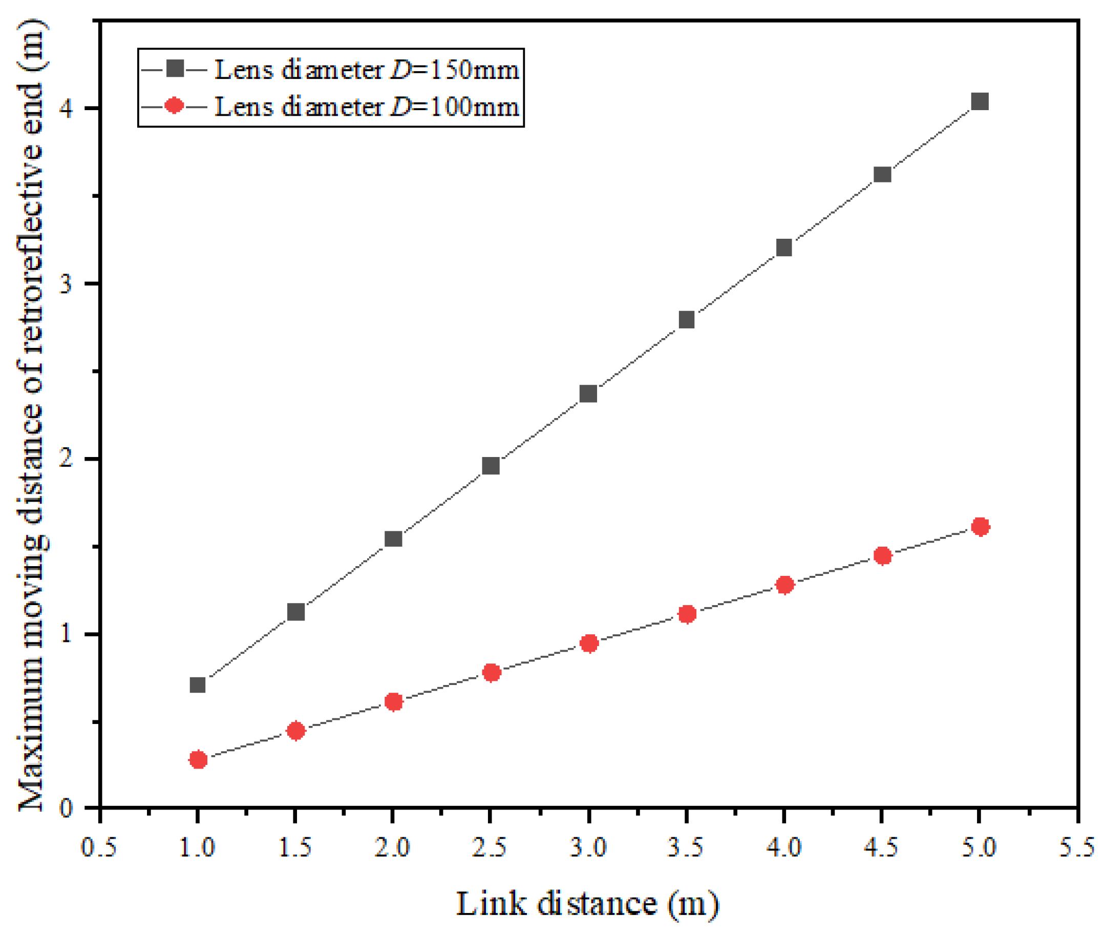
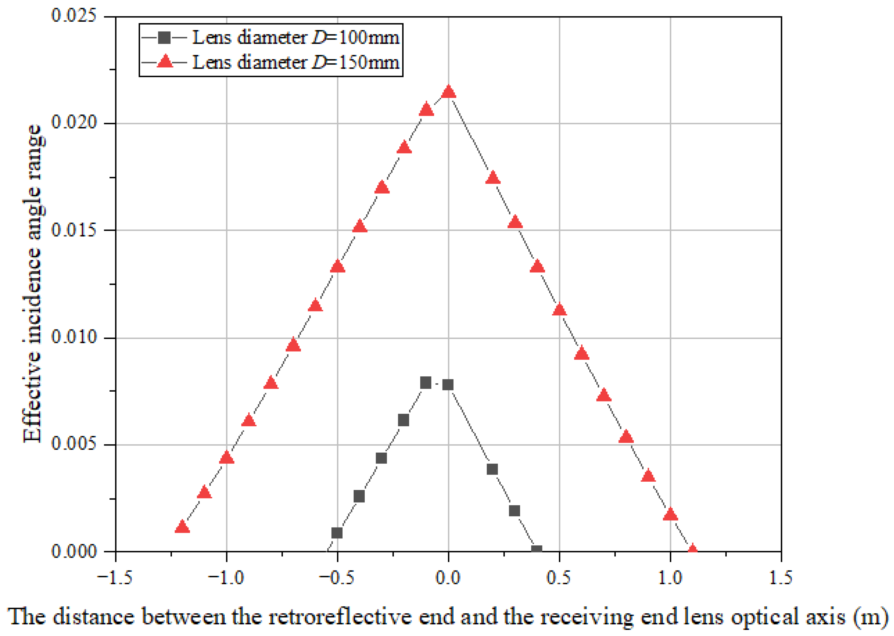
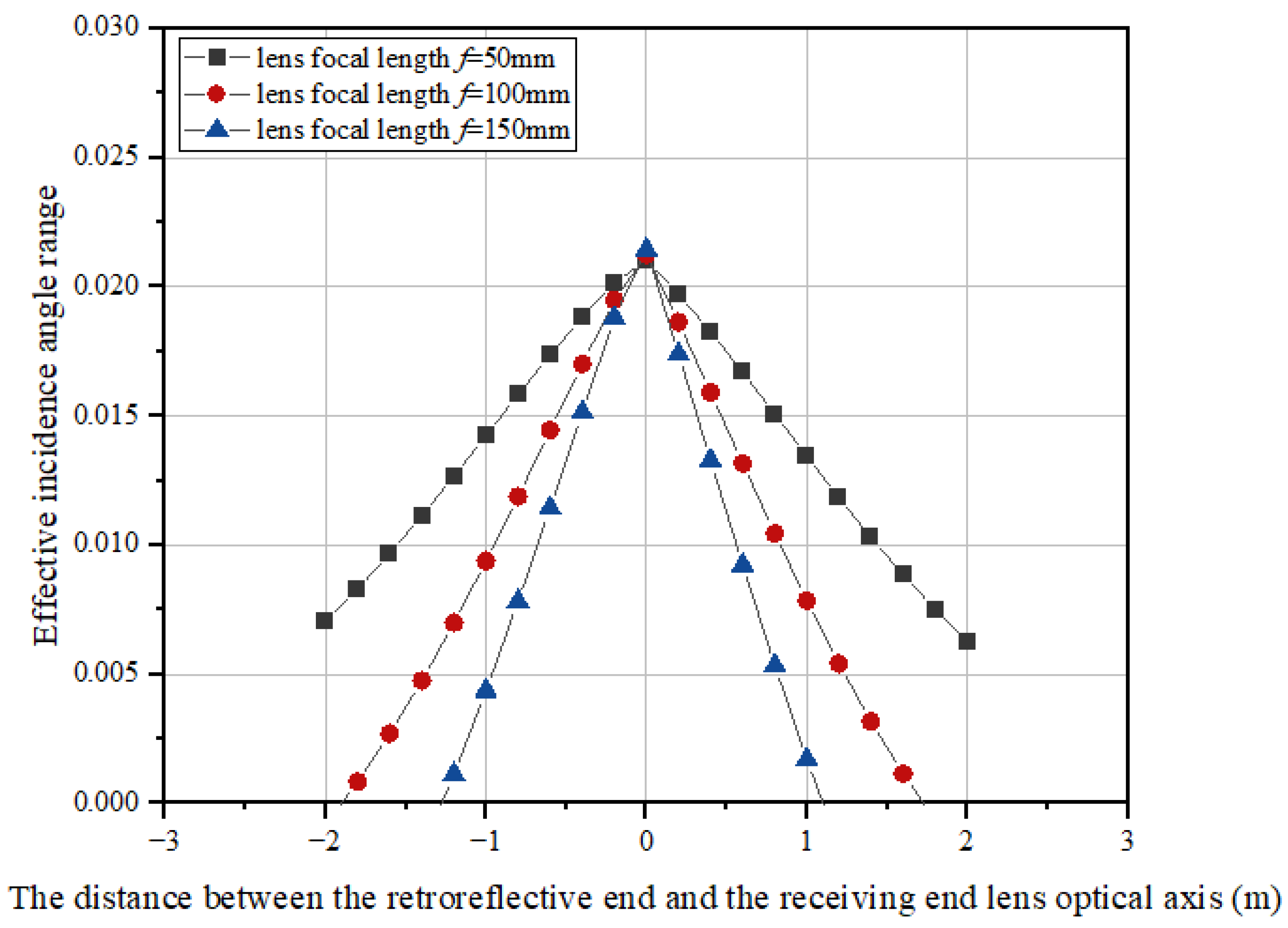
- The effective incidence angle and the maximum travel distance of the reverse reflector represent the effective reflected light power of the system and the movement performance of the reverse reflector, respectively. The results show that increasing the lens aperture, decreasing the lens focal length, and increasing the link distance are conducive to increasing the moving range of the reverse reflector and maintaining the stability of the angle range of the incident light so as to stabilize the power reception at the receiving end.
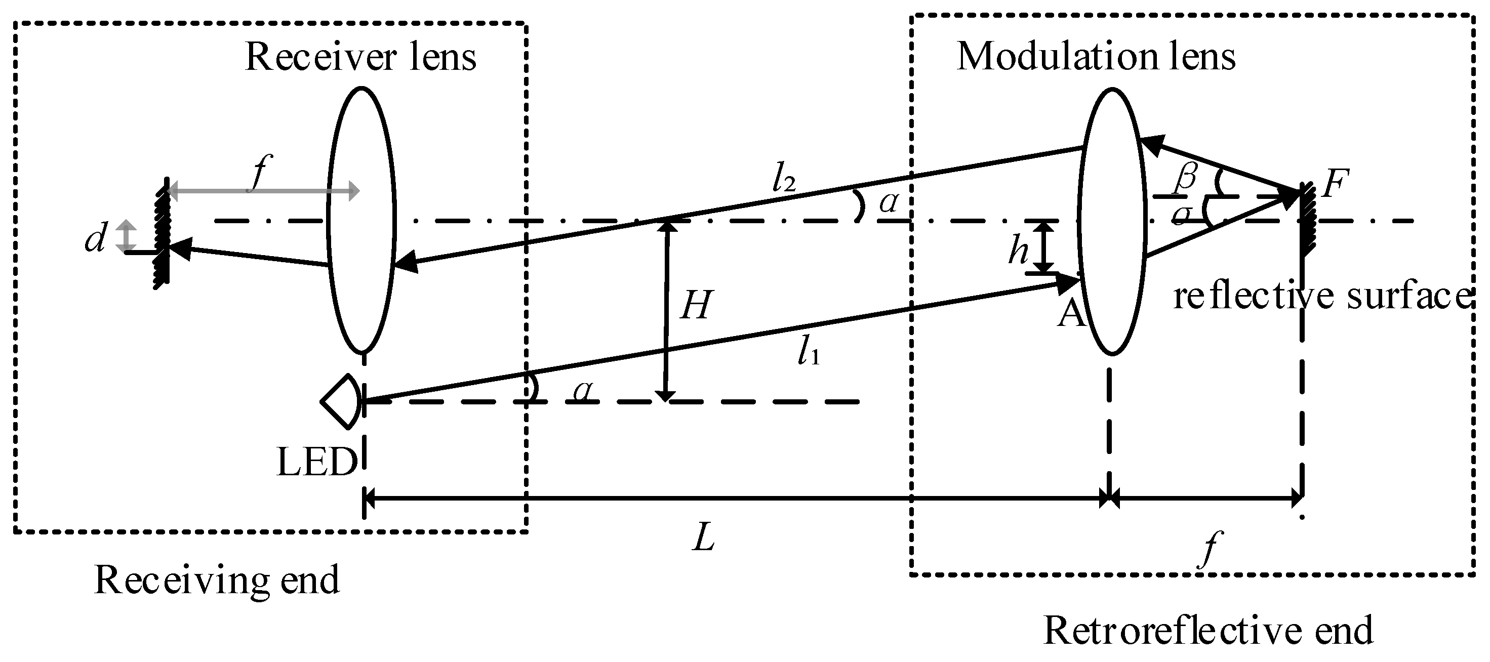
2. System Model
3. Retroreflective End Mobility Analysis
3.1. Lenses at Both Ends Are Coaxial
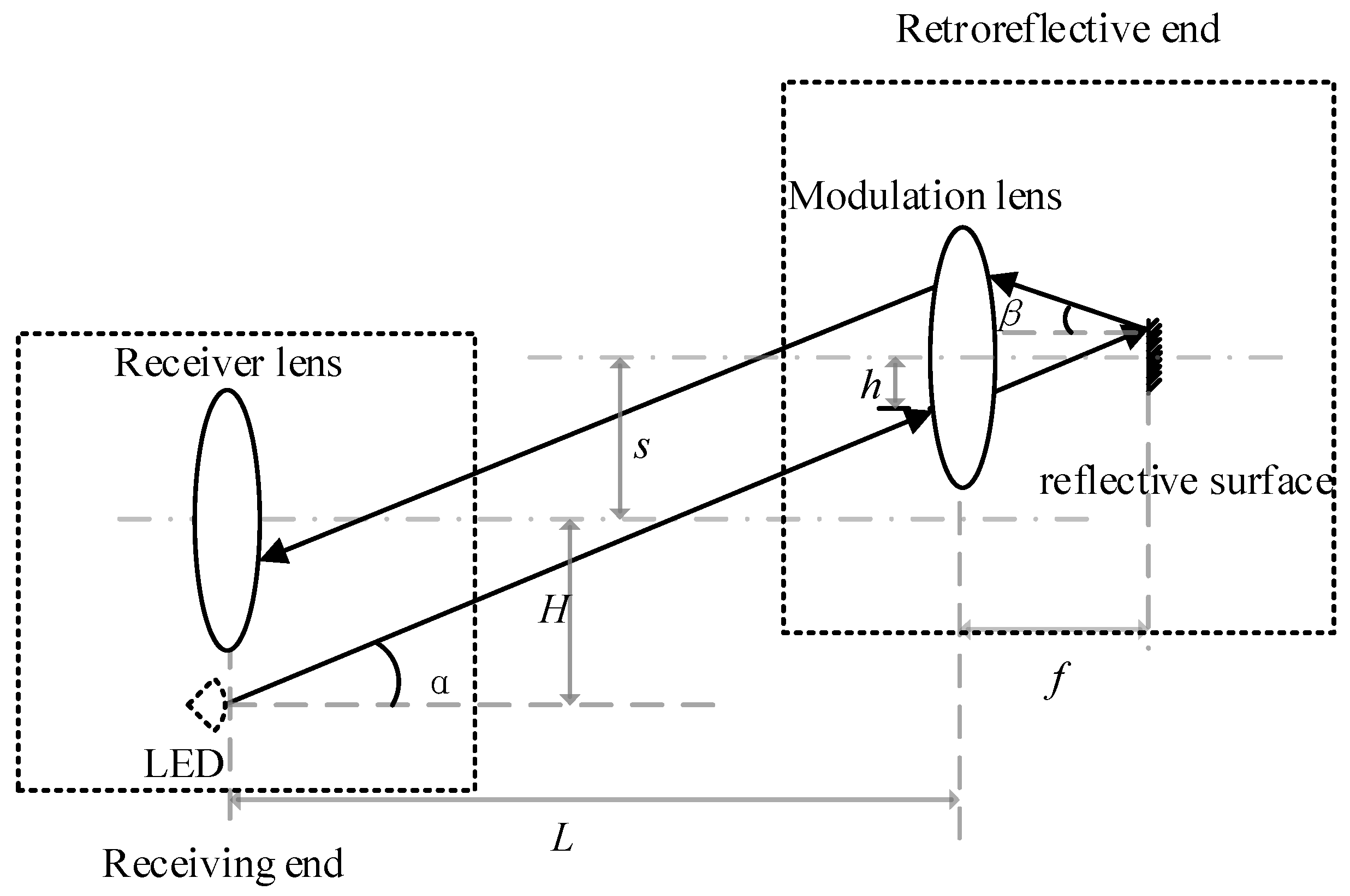
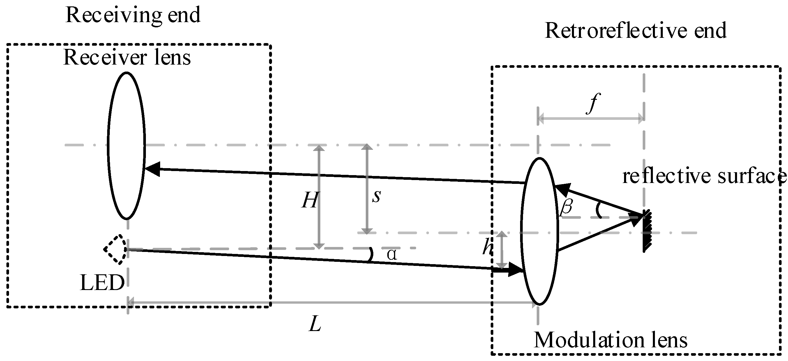
3.2. The Lenses at Both Ends Are Non-Coaxial
3.2.1. When the Optical Axis of the Modulation End Lens Moves Upward
3.2.2. Modulation End Lens Moves Down
4. Numerical Analysis
4.1. Retroreflective End Movable Range
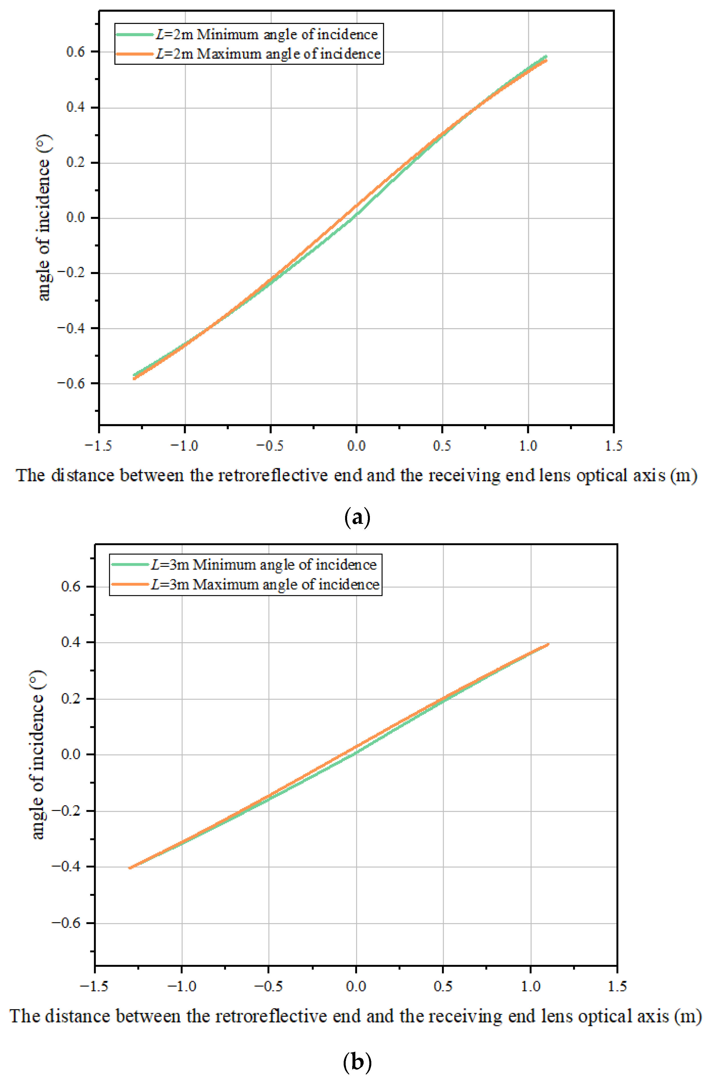
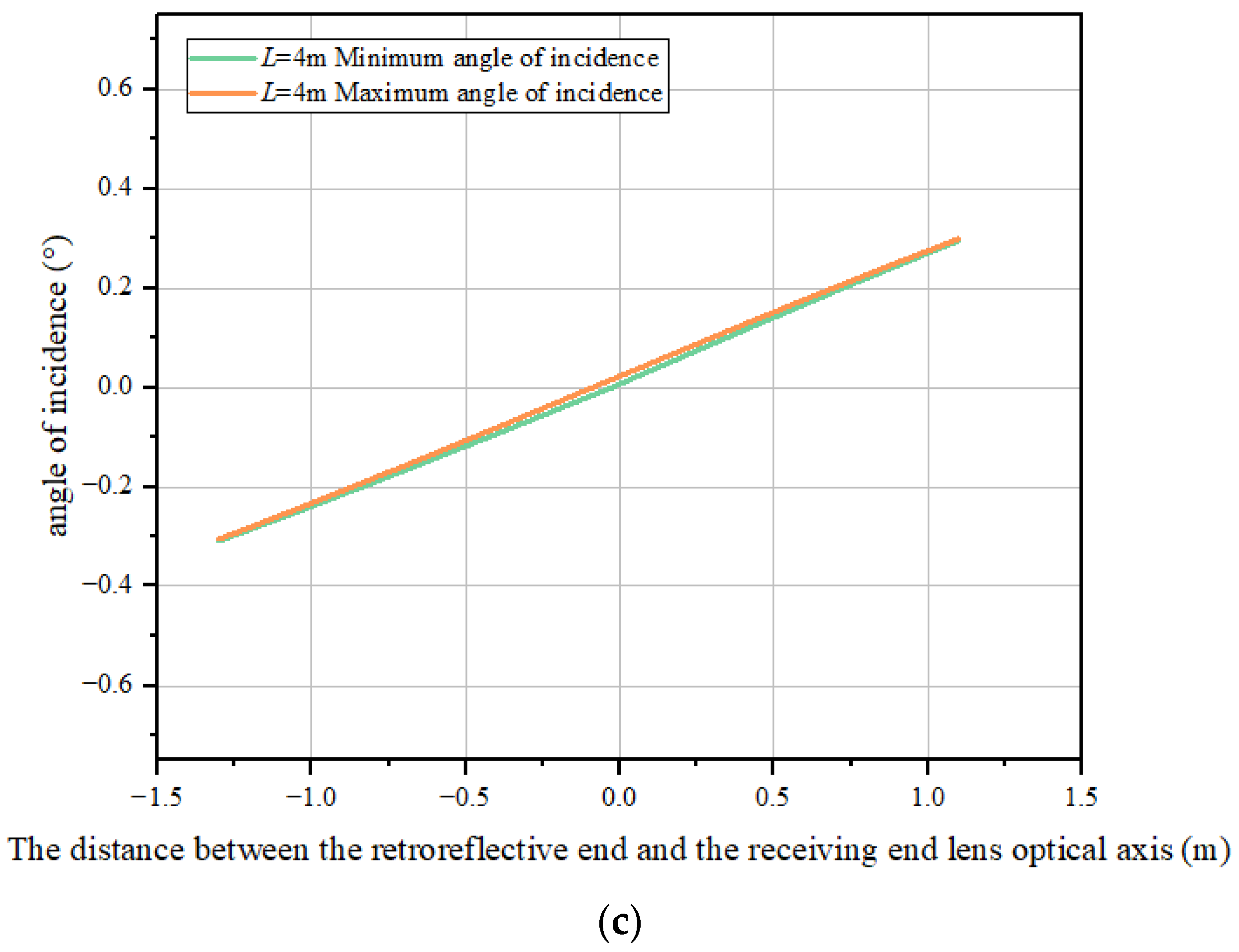
4.2. Effective Angle of Incidence
5. Zemax Simulation Analysis
6. Conclusions
Author Contributions
Funding
Institutional Review Board Statement
Informed Consent Statement
Data Availability Statement
Conflicts of Interest
References
- Koonen, T. Indoor Optical Wireless Systems: Technology, Trends, and Applications. J. Light. Technol. 2018, 36, 1459–1467. [Google Scholar] [CrossRef]
- Feng, L.; Hu, R. Applying VLC in 5G networks: Architectures and key technologies. IEEE Netw. 2016, 30, 77–83. [Google Scholar] [CrossRef]
- Jenila, C.; Jeyachitra, R. Green indoor optical wireless communication systems: Pathway towards pervasive deployment. Digit. Commun. Netw. 2021, 7, 410–444. [Google Scholar] [CrossRef]
- Pang, G.; Kwan, T. Visible light communication for audio systems. IEEE Trans. Consum. Electron. 1999, 45, 1112–1118. [Google Scholar] [CrossRef]
- Tanaka, Y. Wireless optical transmissions with white colored LED for wireless home links. In Proceedings of the 11th IEEE International Symposium on Personal Indoor and Mobile Radio Communications, PIMRC 2000, London, UK, 18–21 September 2000. [Google Scholar]
- Ayyash, M. Coexistence of WiFi and LiFi toward 5G: Concepts, opportunities, and challenges. IEEE Commun. Mag. 2016, 54, 64–71. [Google Scholar] [CrossRef]
- Ilker, D.; Daniel, C. Powering the Internet of Things through Light Communication. IEEE Commun. Mag. 2019, 57, 107–113. [Google Scholar]
- Liu, X.; Huang, S. Joint Resource Allocation and Drones Relay Selection for Large-Scale D2D Communication Underlaying Hybrid VLC/RF IoT Systems. Drones 2023, 7, 589. [Google Scholar] [CrossRef]
- Dhivya, G.; Hariharan, K.; Poonguzhali, P. ILLUMINATE-Visible Light Communication enabled Smart Indoor lighting and control System. In Proceedings of the 2023 25th International Conference on Advanced Communication Technology (ICACT), Pyeongchang, Republic of Korea, 19–22 February 2023. [Google Scholar]
- Zhang, C.; Ge, J.; Pan, M. One Stone Two Birds: A Joint Thing and Relay Selection for Diverse IoT Networks. IEEE Trans. Veh. Technol. 2018, 67, 5424–54348. [Google Scholar] [CrossRef]
- Ariyanti, S. Visible Light Communication (VLC) for 6G Technology: The Potency and Research Challenges. In Proceedings of the 2020 Fourth World Conference on Smart Trends in Systems, Security and Sustainability, London, UK, 27–28 July 2020. [Google Scholar]
- Rui, B.; Iman, T.; Harald, H. 15.73 Gb/s Visible Light Communication with Off-the-Shelf LEDs. J. Light. Technol. 2019, 37, 2418–2424. [Google Scholar]
- Chellam, J.; Jeyachitra, R.K. Energy-efficient bi-directional visible light communication using thin-film corner cube retroreflector for self-sustainable IoT. IET Optoelectron. 2020, 14, 223–233. [Google Scholar] [CrossRef]
- Shao, S.; Salustri, A.; Khreishah, A. R-VLCP: Channel Modeling and Simulation in Retroreflective Visible Light Communication and Positioning Systems. IEEE Internet Things J. 2023, 10, 11429–11439. [Google Scholar] [CrossRef]
- Khan, L. Visible Light Communication: Applications, Architecture, Standardization and Research Challenges. Digit. Commun. Netw. 2017, 3, 78–88. [Google Scholar] [CrossRef]
- Sun, Y.; Ke, X. Analysis of factors affecting the characteristics of reverse modulated reflected light. Infrared Laser Eng. 2016, 45, 222–228. [Google Scholar]
- Wang, L.; Han, D. Deep reinforcement learning-based adaptive handover mechanism for VLC in a hybrid 6G network architecture. IEEE Access 2021, 9, 87241–87250. [Google Scholar] [CrossRef]


| Parameter | Numerical Value |
|---|---|
| LED luminous power | 1 W |
| LED divergence angle | 60° |
| link distance | 3 m |
| Distance between the LED and receiver lens | 180 mm |
| lens material | BK7 |
| Lens diameter | 150 mm |
| lens focal length | 150 mm |
Disclaimer/Publisher’s Note: The statements, opinions and data contained in all publications are solely those of the individual author(s) and contributor(s) and not of MDPI and/or the editor(s). MDPI and/or the editor(s) disclaim responsibility for any injury to people or property resulting from any ideas, methods, instructions or products referred to in the content. |
© 2023 by the authors. Licensee MDPI, Basel, Switzerland. This article is an open access article distributed under the terms and conditions of the Creative Commons Attribution (CC BY) license (https://creativecommons.org/licenses/by/4.0/).
Share and Cite
Zhang, Y.; Ren, J.; Li, K.; Mou, H. Performance Analysis of a Single Light Source Bidirectional Visible Light Communication Reverse Reflection Link. Photonics 2024, 11, 18. https://doi.org/10.3390/photonics11010018
Zhang Y, Ren J, Li K, Mou H. Performance Analysis of a Single Light Source Bidirectional Visible Light Communication Reverse Reflection Link. Photonics. 2024; 11(1):18. https://doi.org/10.3390/photonics11010018
Chicago/Turabian StyleZhang, Ying, Jiawei Ren, Kexin Li, and Haibo Mou. 2024. "Performance Analysis of a Single Light Source Bidirectional Visible Light Communication Reverse Reflection Link" Photonics 11, no. 1: 18. https://doi.org/10.3390/photonics11010018
APA StyleZhang, Y., Ren, J., Li, K., & Mou, H. (2024). Performance Analysis of a Single Light Source Bidirectional Visible Light Communication Reverse Reflection Link. Photonics, 11(1), 18. https://doi.org/10.3390/photonics11010018