A Series of Avoided Crossings of Resonances in the System of Several Different Dielectric Resonators Results in Giant Q-Factors


Abstract
:1. Introduction
2. The Problem Statement
3. A Cascade of Avoided Crossings of Resonances in the System of Several Coaxial Disks
Three Disks
4. Multipole Radiation for Avoided Crossing of Resonances
5. Mode Volumes of Resonances with Extremal -Factor
6. Conclusions and Outlook
Author Contributions
Funding
Data Availability Statement
Acknowledgments
Conflicts of Interest
References
- Mie, G. Beiträge zur Optik trüber Medien, speziell kolloidaler Metallösungen. Ann. Der Phys. 1908, 330, 377–445. [Google Scholar] [CrossRef]
- Colton, D.; Kress, R. Inverse Acoustic and Electromagnetic Scattering Theory, 2nd ed.; Springer: Berlin, Germany, 1998. [Google Scholar]
- Silveirinha, M.G. Trapping light in open plasmonic nanostructures. Phys. Rev. A 2014, 89, 023813. [Google Scholar] [CrossRef]
- Vahala, K. Optical microcavities. Nature 2003, 424, 839–846. [Google Scholar] [CrossRef] [PubMed]
- Ryckman, J.; Weiss, S.M. Low mode volume slotted photonic crystal single nanobeam cavity. Appl. Phys. Lett. 2012, 101, 071104. [Google Scholar] [CrossRef]
- Seidler, P.; Lister, K.; Drechsler, U.; Hofrichter, J.; Stöferle, T. Slotted photonic crystal nanobeam cavity with an ultrahigh quality factor-to-mode volume ratio. Opt. Express 2013, 21, 32468. [Google Scholar] [CrossRef]
- Zhou, J.; Zheng, J.; Fang, Z.; Xu, P.; Majumdar, A. Ultra-low mode volume on substrate silicon nanobeam cavity. Opt. Express 2019, 27, 30692. [Google Scholar] [CrossRef]
- Braginsky, V.; Gorodetsky, M.; Ilchenko, V. Quality-factor and nonlinear properties of optical whispering-gallery modes. Phys. Let. A 1989, 137, 393. [Google Scholar] [CrossRef]
- Gorodetsky, M.; Fomin, A. Geometrical theory of whispering-gallery modes. IEEE J. Sel. Top. Quantum Electron. 2006, 12, 33–39. [Google Scholar] [CrossRef]
- Acharyya, N.; Kozyreff, G. Large Q Factor with Very Small Whispering Gallery Mode Resonators. Phys. Rev. Appl. 2019, 12, 014060. [Google Scholar] [CrossRef]
- Jiang, X.; Qavi, A.; Huang, S.; Yang, L. Whispering-Gallery Sensors. Matter 2020, 3, 371–392. [Google Scholar] [CrossRef]
- Hong, S.H.; Lee, Y.J.; Hong, S.; Kim, Y.; Kwon, S.H. Antisymmetric Mode Cancellation for High-Q Cavities in a Double Disk. Photonics 2022, 9, 572. [Google Scholar] [CrossRef]
- Hsu, C.W.; Zhen, B.; Stone, A.D.; Joannopoulos, J.D.; Soljačić, M. Bound states in the continuum. Nat. Rev. Mater. 2016, 1, 16048. [Google Scholar] [CrossRef]
- Azzam, S.; Kildishev, A. Photonic Bound States in the Continuum: From Basics to Applications. Adv. Opt. Mat. 2020, 9, 2001469. [Google Scholar] [CrossRef]
- Huang, L.; Xu, L.; Woolley, M.; Miroshnichenko, A.E. Trends in Quantum Nanophotonics. Adv. Quantum Technol. 2020, 3, 1900126. [Google Scholar] [CrossRef]
- Joseph, S.; Pandey, S.; Sarkar, S.; Joseph, J. Bound states in the continuum in resonant nanostructures: An overview of engineered materials for tailored applications. Nanophotonics 2021, 10, 4175–4207. [Google Scholar] [CrossRef]
- Koshelev, K.; Sadrieva, Z.; Shcherbakov, A.; Kivshar, Y.; Bogdanov, A. Bound states in the continuum in photonic structures. Uspekhi Fiz. Nauk. 2022, 65, 039120. [Google Scholar] [CrossRef]
- Hsu, C.W.; Zhen, B.; Lee, J.; Johnson, S.G.; Joannopoulos, J.D.; Soljačić, M. Observation of trapped light within the radiation continuum. Nature 2013, 499, 188. [Google Scholar] [CrossRef]
- Bulgakov, E.; Sadreev, A. Bound states in the continuum with high orbital angular momentum in a dielectric rod with periodically modulated permittivity. Phys. Rev. A 2017, 96, 013841. [Google Scholar] [CrossRef]
- Koshelev, K.; Favraud, G.; Bogdanov, A.; Kivshar, Y.; Fratalocchi, A. Nonradiating photonics with resonant dielectric nanostructures. Nanophotonics 2019, 8, 725. [Google Scholar] [CrossRef]
- Taghizadeh, A.; Chung, I.S. Quasi bound states in the continuum with few unit cells of photonic crystal slab. Appl. Phys. Lett. 2017, 111, 031114. [Google Scholar] [CrossRef]
- Bulgakov, E.; Sadreev, A. Propagating Bloch bound states with orbital angular momentum above the light line in the array of dielectric spheres. J. Opt. Soc. Am. A 2017, 34, 949. [Google Scholar] [CrossRef] [PubMed]
- Sadrieva, Z.F.; Belyakov, M.A.; Balezin, M.A.; Kapitanova, P.V.; Nenasheva, E.A.; Sadreev, A.F.; Bogdanov, A.A. Experimental observation of a symmetry-protected bound state in the continuum in a chain of dielectric disks. Phys. Rev. A 2019, 99, 053804. [Google Scholar] [CrossRef]
- Polishchuk, I.Y.; Anastasiev, A.A.; Tsyvkunova, E.A.; Gozman, M.I.; Solov’ov, S.V.; Polishchuk, Y.I. Guided modes in the plane array of optical waveguides. Phys. Rev. A 2017, 95, 053847. [Google Scholar] [CrossRef]
- Sidorenko, M.; Sergaeva, O.; Sadrieva, Z.; Roques-Carmes, C.; Muraev, P.; Maksimov, D.; Bogdanov, A. Observation of an Accidental Bound State in the Continuum in a Chain of Dielectric Disks. Phys. Rev. Appl. 2021, 15, 034041. [Google Scholar] [CrossRef]
- Bulgakov, E.; Sadreev, A. High-Q resonant modes in a finite array of dielectric particles. Phys. Rev. A 2019, 99, 033851. [Google Scholar] [CrossRef]
- Bulgakov, E.; Maksimov, D. Q -factor optimization in dielectric oligomers. Phys. Rev. A 2019, 100, 033830. [Google Scholar] [CrossRef]
- Kornovan, D.F.; Savelev, R.S.; Kivshar, Y.; Petrov, M.I. High-Q Localized States in Finite Arrays of Subwavelength Resonators. ACS Photonics 2021, 8, 3627–3632. [Google Scholar] [CrossRef]
- Gao, Y.; Shi, Y. Design of a Single Nanoparticle Trapping Device Based on Bow-Tie-Shaped Photonic Crystal Nanobeam Cavities. IEEE Photonics J. 2019, 11, 2911291. [Google Scholar] [CrossRef]
- Von Brentano, P. On the generalization of the level repulsion theorem to resonances. Phys. Lett. B 1990, 238, 1–5. [Google Scholar] [CrossRef]
- Heiss, W.D. Repulsion of resonance states and exceptional points. Phys. Rev. E 2000, 61, 929–932. [Google Scholar] [CrossRef]
- Cao, H.; Wiersig, J. Dielectric microcavities: Model systems for wave chaos and non-Hermitian physics. Rev. Mod. Phys. 2015, 87, 61. [Google Scholar] [CrossRef]
- Bernier, N.R.; Tóth, L.D.; Feofanov, A.K.; Kippenberg, T.J. Level attraction in a microwave optomechanical circuit. Phys. Rev. A 2018, 98, 023841. [Google Scholar] [CrossRef]
- Wiersig, J. Formation of Long-Lived, Scarlike Modes near Avoided Resonance Crossings in Optical Microcavities. Phys. Rev. Lett. 2006, 97, 253901. [Google Scholar] [CrossRef] [PubMed]
- Song, Q.H.; Cao, H. Improving Optical Confinement in Nanostructures via External Mode Coupling. Phys. Rev. Lett. 2010, 105, 053902. [Google Scholar] [CrossRef]
- Rybin, M.; Koshelev, K.; Sadrieva, Z.; Samusev, K.; Bogdanov, A.; Limonov, M.; Kivshar, Y. High-Q Supercavity Modes in Subwavelength Dielectric Resonators. Phys. Rev. Lett. 2017, 119, 243901. [Google Scholar] [CrossRef]
- Koshelev, K.; Bogdanov, A.; Kivshar, Y. Meta-optics and bound states in the continuum. Sci. Bull. 2018, 17, 065601. [Google Scholar] [CrossRef]
- Chen, W.; Chen, Y.; Liu, W. Multipolar Conversion Induced Subwavelength High-Q Kerker Supermodes with Unidirectional Radiations. Laser Photonics Rev. 2019, 13, 1900067. [Google Scholar] [CrossRef]
- Wang, W.; Zheng, L.; Xiong, L.; Qi, J.; Li, B. High Q-factor multiple Fano resonances for high-sensitivity sensing in all-dielectric metamaterials. OSA Contin. 2019, 2, 2818. [Google Scholar] [CrossRef]
- Odit, M.; Koshelev, K.; Gladyshev, S.; Ladutenko, K.; Kivshar, Y.; Bogdanov, A. Observation of Supercavity Modes in Subwavelength Dielectric Resonators. Adv. Mater. 2020, 33, 2003804. [Google Scholar] [CrossRef]
- Volkovskaya, I.; Xu, L.; Huang, L.; Smirnov, A.; Miroshnichenko, A.; Smirnova, D. Multipolar second-harmonic generation from high-Q quasi-BIC states in subwavelength resonators. Nanophotonics 2020, 9, 3953. [Google Scholar] [CrossRef]
- Huang, L.; Xu, L.; Rahmani, M.; Neshev, D.; Miroshnichenko, A. Pushing the limit of high-Q mode of a single dielectric nanocavity. Adv. Photonics 2021, 3, 016004. [Google Scholar] [CrossRef]
- Boriskina, S.V. Theoretical prediction of a dramatic Q-factor enhancement and degeneracy removal of whispering gallery modes in symmetrical photonic molecules. Opt. Lett. 2006, 31, 338. [Google Scholar] [CrossRef] [PubMed]
- Boriskina, S. Coupling of whispering-gallery modes in size-mismatched microdisk photonic molecules. Opt. Lett. 2007, 32, 1557. [Google Scholar] [CrossRef]
- Benyoucef, M.; Shim, J.B.; Wiersig, J.; Schmidt, O.G. Quality-factor enhancement of supermodes in coupled microdisks. Opt. Lett. 2011, 36, 1317. [Google Scholar] [CrossRef] [PubMed]
- Chang, S.H.G.; Sun, C.Y. Avoided resonance crossing and non-reciprocal nearly perfect absorption in plasmonic nanodisks with near-field and far-field couplings. Opt. Express 2016, 24, 16822. [Google Scholar] [CrossRef] [PubMed]
- Pichugin, K.N.; Sadreev, A.F. Interaction between coaxial dielectric disks enhances the Q factor. J. Appl. Phys. 2019, 126, 093105. [Google Scholar] [CrossRef]
- Bulgakov, E.N.; Pichugin, K.N.; Sadreev, A.F. Evolution of the resonances of two parallel dielectric cylinders with distance between them. Phys. Rev. A 2019, 100, 043806. [Google Scholar] [CrossRef]
- Dmitriev, A.; Rybin, M. Combining isolated scatterers into a dimer by strong optical coupling. Phys. Rev. A 2019, 99, 063837. [Google Scholar] [CrossRef]
- Vinel, V.; Li, Z.; Borne, A.; Bensemhoun, A.; Favero, I.; Ciuti, C.; Leo, G. Non-Hermitian bath model for arrays of coupled nanoresonators. Opt. Express 2021, 29, 34015. [Google Scholar] [CrossRef]
- Bulgakov, E.; Pichugin, K.; Sadreev, A. Mie Resonance Engineering in Two Disks. Photonics 2021, 8, 49. [Google Scholar] [CrossRef]
- Pichugin, K.; Sadreev, A.; Bulgakov, E. Ultrahigh-Q system of a few coaxial disks. Nanophotonics 2021, 10, 4341–4346. [Google Scholar] [CrossRef]
- Kitamura, R.; Pilon, L.; Jonasz, M. Optical constants of silica glass from extreme ultraviolet to far infrared at near room temperature. Appl. Optics 2007, 46, 8118. [Google Scholar] [CrossRef]
- Jackson, J.D. Classical Electrodynamics; John Wiley and Sons, Inc.: New York, NY, USA, 1962. [Google Scholar]
- Bogdanov, A.; Koshelev, K.; Kapitanova, P.; Rybin, M.; Gladyshev, S.; Sadrieva, Z.; Samusev, K.; Kivshar, Y.; Limonov, M.F. Bound states in the continuum and Fano resonances in the strong mode coupling regime. Adv. Photonics 2019, 1, 016001. [Google Scholar] [CrossRef]
- Sadrieva, Z.; Frizyuk, K.; Petrov, M.; Kivshar, Y.; Bogdanov, A. Multipolar origin of bound states in the continuum. Phys. Rev. B 2019, 100, 115303. [Google Scholar] [CrossRef]
- Stratton, J.A. Electromagnetic Theory; McGraw-Hill Book Company, Inc.: New York, NY, USA, 1941. [Google Scholar]
- Linton, C.; Zalipaev, V.; Thompson, I. Electromagnetic guided waves on linear arrays of spheres. Wave Motion 2013, 50, 29–40. [Google Scholar] [CrossRef]
- Bulgakov, E.; Pichugin, K.; Sadreev, A. Exceptional points in a dielectric spheroid. Phys. Rev. A 2021, 104, 053507. [Google Scholar] [CrossRef]
- Doicu, A.; Wriedt, T.; Eremin, Y.A. Light Scattering by Systems of Particles; Springer: Berlin/Heidelberg, Germany, 2006. [Google Scholar] [CrossRef]
- Hu, S.; Weiss, S. Design of Photonic Crystal Cavities for Extreme Light Concentration. ACS Photonics 2016, 3, 1647. [Google Scholar] [CrossRef]
- Vennberg, F.; Ravishankar, A.; Anand, S. Manipulating light scattering and optical confinement in vertically stacked Mie resonators. Nanophotonics 2022, 11, 4755. [Google Scholar] [CrossRef]
- Maslova, E.; Rybin, M.; Bogdanov, A.; Sadrieva, Z. Bound states in the continuum in periodic structures with structural disorder. Nanophotonics 2021, 10, 4313–4321. [Google Scholar] [CrossRef]
- Kim, S.; Kim, K.H.; Cahoon, J. Optical Bound States in the Continuum with Nanowire Geometric Superlattices. Phys. Rev. Lett. 2019, 122, 187402. [Google Scholar] [CrossRef]


| Mode Profile | Scales | Re (kr) | Q | ||
|---|---|---|---|---|---|
| 1 |  | 1.72 | 1.4 | ||
| 2 |  | | 1.76 | 1.6 | |
| 3 |  | | 1.75 | 1.6 | |
| 4 |  | | 1.76 | 1.4 | |
| 5 | 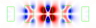 | | 1.77 | 1.7 | |
| 6 |  | 2.19 | 1.9 | ||
| 7 | 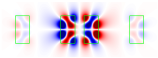 | | 2.19 | 2 | |
| 8 |  | | 2.2 | 2.1 | |
| 9 | 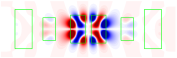 | | 2.2 | 2.1 | |
| 10 | 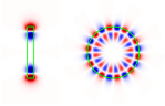 | 4.76 | 4.9 | ||
| 11 | 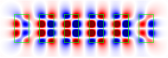 | | 2.19 | 4.4 |
Disclaimer/Publisher’s Note: The statements, opinions and data contained in all publications are solely those of the individual author(s) and contributor(s) and not of MDPI and/or the editor(s). MDPI and/or the editor(s) disclaim responsibility for any injury to people or property resulting from any ideas, methods, instructions or products referred to in the content. |
© 2023 by the authors. Licensee MDPI, Basel, Switzerland. This article is an open access article distributed under the terms and conditions of the Creative Commons Attribution (CC BY) license (https://creativecommons.org/licenses/by/4.0/).
Share and Cite
Pichugin, K.; Sadreev, A.; Bulgakov, E. A Series of Avoided Crossings of Resonances in the System of Several Different Dielectric Resonators Results in Giant Q-Factors. Photonics 2023, 10, 973. https://doi.org/10.3390/photonics10090973
Pichugin K, Sadreev A, Bulgakov E. A Series of Avoided Crossings of Resonances in the System of Several Different Dielectric Resonators Results in Giant Q-Factors. Photonics. 2023; 10(9):973. https://doi.org/10.3390/photonics10090973
Chicago/Turabian StylePichugin, Konstantin, Almas Sadreev, and Evgeny Bulgakov. 2023. "A Series of Avoided Crossings of Resonances in the System of Several Different Dielectric Resonators Results in Giant Q-Factors" Photonics 10, no. 9: 973. https://doi.org/10.3390/photonics10090973
APA StylePichugin, K., Sadreev, A., & Bulgakov, E. (2023). A Series of Avoided Crossings of Resonances in the System of Several Different Dielectric Resonators Results in Giant Q-Factors. Photonics, 10(9), 973. https://doi.org/10.3390/photonics10090973