Abstract
The propagation and scattering of vortex light beams in complex media have significant implications in the fields of laser imaging, optical manipulation, and communication. This paper investigates the scattering characteristics of vortex light beams from a random rough surface. Firstly, a two-dimensional Gaussian rough surface is generated using the Monte Carlo method combined with the linear filtering method. Subsequently, the vortex beams are decomposed into the superposition of infinite plane waves, and the scattering of each plane wave from the rough surface is calculated using the Kirchhoff Approximation method. Numerical results of the angle distribution and spatial distribution of OAM scattering Laser Radar Cross Section (LRCS) are presented, varying with different surface roughness parameters for a rough aluminum surface and the beam’s parameters. The results demonstrate that the scattering of vortex beams is influenced by the beam’s parameters, such as Orbital Angular Momentum (OAM) mode number and elevation angle, which may bring new insights into vortex wave-matter interactions and their applications in high resolution imaging.
1. Introduction
Vortex beams carrying Orbital Angular Momentum (OAM) exhibit a phase singularity with a specific OAM mode number, resulting in a hollow intensity distribution. This distinctive property enables the vortex wave to modulate information by manipulating the phase structure of the optical vortex [1]. Exciting research has been focused on utilizing OAM across various frequency ranges, including visible, infrared, terahertz, and millimeter wavelengths [2,3,4,5]. The vortex wave-matter interactions in the infrared region plays a crucial role and is highly demanded in wide-ranging applications, including (but not limited to) optical communication [6], astronomic observation [7], defect detection, and infrared sensing [8].
In the past few years, significant efforts have been devoted to investigating vortex beam generation, propagation, and communication applications. Allen et al. first proposed Orbital Angular Momentum in vortex beams, which unveiled a new understanding of the connection between macroscopic optics and quantum effects [9]. Garcés-Chávez et al. experimentally demonstrated that a high order Bessel beam possesses OAM and can transfer OAM to trap transparent particles in optical tweezers [10]. Li simulated the echo speckle characteristics of Laguerre–Gauss (LG) vortex beams scattered from random rough surface targets based on the Rytov Approximation Theory. The results showed that in weak turbulence regions, the target characteristics were the primary influencing factors of the speckle fields [11]. Ju investigated vortex beam propagation characteristics generated by a coherent laser array using the random phase screens simulation in atmosphere and proposed a scheme of an optical communication system simultaneously possessing polarization-division multiplexing and OAM multiplexing [12]. Dong established a double-passage propagation model of partially coherent LG vortex beams with OAM modes in turbulent atmosphere after scattering from Gaussian rough surfaces. Based on this model, the light intensity and phase distribution, beam spreading, and OAM spectrum of vortex beams scattered by random Gaussian rough surfaces were analyzed [13].
Considering that laser radar offers superior resolution compared to microwave radar, the development of target recognition applications using vortex beams requires a fundamental understanding of the interaction mechanism of OAM modes with various objects. The generalized Lorenz–Mie theory has been widely used to solve the scattering problem of spherical [14] or a multilayered chiral sphere illuminated by vortex beams [15]. By expanding the beam field in terms of cylindrical waves, the scattering of an E-polarized electromagnetic vortex Bessel beam by a gyrotropic cylinder was studied in [16]. However, most of these studies focused on regular objects such as particles or cylinders. There is limited research on vortex beams scattering from rough surfaces due to the randomness and irregularity of the surface, making it difficult to obtain a rigorous analytical expression for surface scattering. Previous studies on the scattering statistics of rough surfaces for both light waves [17] and radio waves [18] have been made in the scopes of both depth and breadth. A theoretical scattering model from a rough soil surface covering a wide range of surface parameters was established by the advanced integral equation model (AIEM) in [19]. Jin investigated the dominant factors for the Very High-Resolution (VHR) radar image speckles from exponentially correlated rough surfaces using the Finite-Difference Time-Domain (FDTD) method [20]. However, these numerical algorithms are not applicable in the infrared band due to the large number of unknowns. Therefore, in this study, we utilize the Kirchhoff Approximation method to calculate the OAM wave scattering field from rough surfaces in the infrared band.
In our previous work, we obtained approximate numerical results of typical targets by plane wave expansion and coordinate system transformation [21]. Studying the scattering of vortex beams from rough surfaces may bring new insights into the vortex wave-matter interaction as well as new applications. Motivated by the features and applications of vortex beams, we undertake analytical and numerical simulations for the scattering of vortex beams from a rough surface. This paper is organized as follows. In Section 2, a two-dimensional Gaussian rough surface is generated and the electric field of vortex beams with a certain OAM mode number is decomposed into the superposition of infinite plane waves according to the electromagnetic theory and the spectral domain method. Moreover, the analytical solutions of the scattering interactions between the vortex beams and the rough aluminum surface are presented using the Kirchhoff Approximation method. Section 3 presents numerical simulations for different parameters. We discuss the results in Section 4, followed by the conclusion in Section 5.
2. Methods
2.1. Gaussian Rough Surface Generation
The two-dimensional (2D) Gaussian rough surface was generated by a combination of the Monte Carlo method and the linear filtering method. In the linear filtering method, the 2D Gaussian rough surface is regarded as a series of harmonics with different wavelengths, periods, and initial phases. The amplitude of these harmonics are independent Gaussian random variables {}, with the real and imaginary parts following a standard normal distribution, respectively.
The height of the rough surface can be expressed as
where Lx and Ly correspond to the lengths of the rough surface in the x and y directions, respectively. The spatial wave numbers are discretized into and along the x and y directions, respectively, with M and N denoting the number of discrete points. When M or N is even, the Fourier coefficient in Equation (1) is
When M or N is odd, the Fourier coefficient in Equation (1) is
where is a random number and obeys the standard normal distribution, and the coefficient “2” before is to ensure that the amplitude distribution of the zero-frequency component is consistent with that of other frequency components. To enhance the computational efficiency of the Two-Dimensional Inverse Fourier Transform (2DIFT), we opt for even values of M and N in this study.
The power spectral density, , of the 2D Gaussian rough surface in Equations (2) and (3) takes the form of
where is the root mean square (RMS) of the surface height and is the correlation length in the x and y directions.
It is noted that in practical computer simulation, Equation (1) can be obtained using 2D Inverse Fast Fourier transform (IFFT). Figure 1 presents rough surfaces with varying roughness parameters. The simulated parameters are as follows: the number of discrete points is M = N = 256 and the length is Lx = Ly = 1000λ, with λ = 10.3531 μm. The roughness parameters corresponding to Figure 1a–c are (surface I), (surface II), and (surface III), respectively. It is evident that the roughness parameter is a significant factor influencing the surface undulations. Figure 1d illustrates the difference of the surface height for the same RMS but varying correlation lengths, while Figure 1e depicts the difference of the surface height for the same correlation length but varying RMS. It can be observed that the RMS has a greater impact on surface undulations compared to the correlation length. As the RMS increases, the surface undulations of the rough surface also increase.
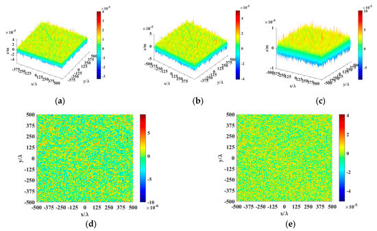
Figure 1.
Gaussian surfaces: (a) surface I: ; (b) surface II: ; (c) surface III: . (d) Height difference between surface I and surface II. (e) Height difference between surface II and surface III.
2.2. Vortex Wave Scattering Model from a Rough Surface
Based on our previous work, the electric field of vortex waves can be decomposed into the superposition of plane waves with different elevation angle, , and azimuthal angle, , which determines the propagation direction of decomposed plane waves. The transverse electric field of the incident vortex beams can be expressed as [21]
where a and b are complex amplitude of the x and y components of the electric field, which also denote polarizations of OAM waves. The polarization of the OAM wave in this paper is set as linear, with for HH polarization and for VV polarization. Subscript b represents the beam coordinate to distinguish it from the scattering coordinate, is the radial length, and denotes the azimuthally spatial location of waves in the cylindrical coordinate and .
As shown in Figure 2, the incident and scattered wave vector of the vortex waves can be expressed as:
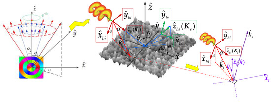
Figure 2.
Geometry for Vortex light beam scattering from a rough surface.
The beam incident coordinates can be expressed in the global coordinates by setting (the horizontal polarization) to be and (the vertical polarization) to be . Then, the incident wave vectors, , of each plane wave after decomposition can be expressed in the global coordinate system as
The scattering of each plane wave with a specific amplitude and phase distribution determined by a specific elevation angle, , and a set of distributed azimuth angles () needs to be separately solved. Kirchhoff Approximation (KA) is used in this paper to calculate the scattered echo of the rough surface illumined by each decomposed plane wave as follows [22]:
where subscript N represents the nth decomposed plane wave, . is the polarization coefficient with the form of
where , and are as below
where is the Fresnel reflection coefficient and is the relative dielectric constant. In this paper, we chose Aluminum as the material of rough surface. Table 1 shows the complex permittivity of aluminum in infrared bands at a temperature of [23]. is the incident angle for each decomposed plane wave, which is determined by in Equation (7) and the local normal vector of the discrete rough surface. Similarly, is the scattering angle for each decomposed plane wave, which is determined by in Equation (6) and the local normal vector of the discrete rough surface. and represent the slope of the two-dimensional surface in the x and y directions, respectively.

Table 1.
Permittivity of aluminum in infrared band at .
In this paper, we assume that the OAM waves are composed of only a set of plane waves with a single elevation angle, α. Then the final total scattering field can be obtained by superimposing the scattering fields of each plane wave:
Laser Radar Cross Section (LRCS) is utilized to describe the laser radar echo characteristics of the target. The normalized LRCS through irradiated area, , denoted as the scattering coefficient, is as follows:
3. Numerical Results
In this section, the cross sections of OAM waves’ transverse electric fields in the infrared band, the normalized LRCS from the rough surface, and the spatial distribution of LRCS for the rough surface illuminated by the vortex beams are to be presented.
3.1. Cross Sections of OAM Waves’ Transverse Electric Fields
Figure 3 and Figure 4 show the cross sections of OAM waves’ transverse electric fields in the infrared band, characterized by distinct OAM mode (l) and elevation angles (). The wavelength of the incident beam is λ = 10.3531 μm. It can be seen that, for OAM modes l =−1 and l =1, the amplitude of the incident OAM waves’ transverse electric field exhibits a hollow intensity distribution, while the phase changes from 0 to in a period of azimuth angle. Furthermore, a reversal in the phase distribution occurs when there is a change in sign of the OAM mode number. This reversal is a result of the field’s sign changes. Moreover, for OAM modes l = 2 and l = 3, the intensity hollow is no longer a perfect round hole. We can also observe that the phase changes l times from 0 to in the azimuth angle direction. Comparing Figure 3 and Figure 4 with different elevation angles (), we can observe that an increase in the elevational angle results in more fluctuation changes for both the amplitude and phase distribution with the same radii of cross sections.
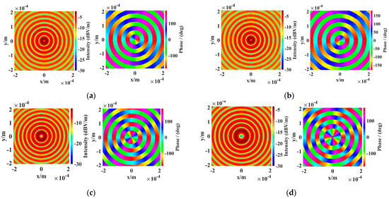
Figure 3.
Transverse electric fields of incident OAM waves with : (a) ; (b) ; (c) ; (d) .
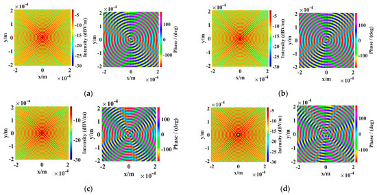
Figure 4.
Transverse electric fields of incident OAM waves with : (a) ; (b) ; (c) ; (d) .
3.2. Normalized LRCS from Rough Surface
Figure 5 shows numerical results for the backscattering normalized LRCS of a rough aluminum surface with a size of 1000λ × 1000λ, as shown in Figure 1. Note that the OAM wave with OAM mode is equivalent to a plane wave. To demonstrate the validity of the proposed method, letting and , the incident angle and scattering angle is set as . Remarkably good agreements are observed in Figure 4a between the backscattering LRCS angular distribution of the rough aluminum surface induced by the decomposed OAM wave and the plane wave.
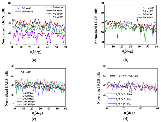
Figure 5.
Normalized LRCS from Gaussian surface for OAM waves incidence: (a) , λ = 10.3531 μm; (b) , λ = 10.3531 μm; (c) , l = 1 with different wavelength of OAM waves; (d) , l = 1 with different surface.
Figure 5a,b illustrates the angle distribution of the normalized LRCS for different OAM modes with elevational angles and . It can be observed that the results for and are approximately equal. This is due to the fact that the sign of the OAM mode has a negligible effect on the intensity distribution of the incident OAM waves, with its influence limited only to the phase of the field. However, this influence on the phase distribution, after interacting with a rough surface, can lead to differences in the normalized LRCS. Additionally, we can observe that the normalized LRCS decreases with an increase in OAM mode for both values. Figure 5c presents the influence of different incident wavelengths on scattering. It can be seen that the normalized LRCS increases as the incident wavelength decreases, which is due to the incident wave with shorter wavelength being able to interact with the fine structures of the rough surface, resulting in a further increase in the scattering results. Figure 5d presents the scattering results for different roughness parameters. It can be observed that as the roughness increases, there is a slight increase for the backscattering normalized LRCS in large incident angle. We will discuss the effect of the RMS of height on the scattering characteristics in detail in Section 4.
3.3. Spatial Distribution of LRCS from Rough Surface
Figure 6 presents the spatial distribution of LRCS F from surface I under different vortex wave parameters. It should be noted that for clearer display, we have only shown a quarter of the simulated area. This image illustrates the spatial distribution of the OAM scattering LRCS of each facet of the rough surface. We can see that the scattering intensity varies differently with the change of OAM mode for different incident angles. At an incident angle of 20°, the OAM scattering LRCS exhibits a relatively higher value for OAM mode l = 3 compared to modes l = 1 and l = 2, while at an incident angle of 45°, the OAM scattering LRCS is relatively higher for OAM mode l =2 compared to modes l = 1 and l = 3. This contradicts the conclusion that the normalized LRCS decreases with an increase in OAM mode drawn in Figure 5, which is attributed to the coherent superposition between surface facets. Figure 7 depicts the spatial distribution of OAM scattering LRCS from a rough surface with . By comparing Figure 6 and Figure 7, it can be observed that for the same incident angle, the normalized LRCS decreases as the elevational angle increases.
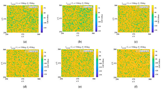
Figure 6.
The spatial distribution of LRCS from Gaussian surface I for OAM wave incidence with α = 10°: (a) l = 1, 20° incidence; (b) l = 2, 20° incidence; (c) l = 3, 20° incidence; (d) l = 1, 45° incidence; (e) l = 2, 45° incidence; (f) l = 3, 45° incidence.

Figure 7.
The spatial distribution of LRCS from Gaussian surface I for OAM waves incidence with α = 30° and 45° incidence: (a) l = 1; (b) l = 2; (c) l = 3.
4. Discussions
In this section, we present numerical results of the bistatic OAM scattering distribution with scattering angle. We also discuss the challenges of the proposed model and its potential applications in the future.
To further illustrate the effect of surface roughness on the scattering characteristics, we set the roughness parameters as , , and , with the same correlation length, . The wavelength of the OAM wave is λ = 10.3531 μm, with an incident angle of 30°. Figure 8 depicts the distribution of bistatic scattering NLRCS with scattering angle , both for plane waves and OAM waves. It can be seen that the trends of the two curves of the plane wave and OAM wave scattering are roughly the same, except for different magnitudes. For rough surfaces with small roughness, the scattered power is mainly concentrated in the mirror area (i.e., the scattering angle is −45°~−15° for a 30° incidence). As the roughness increases, the mirror component decreases, and diffuse reflection dominates. This occurs because the normal vector of the tangent plane for rough surfaces with lower roughness is basically perpendicular to the entire rough surface, while the direction of the normal vector of the tangent plane for rough surfaces with large roughness becomes more dispersed.
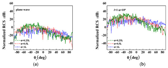
Figure 8.
The distribution of bistatic scattering NLRCS with scattering angle for a 30° incidence: (a) plane wave incidence; (b) OAM wave incidence with l = 1, .
Furthermore, we have presented the transverse electric fields of incident vortex light beams by integrating elevation angles, , as shown in Figure 9. We found that after integrating elevation angles, phase discontinuity occurs, which is attributed to the cumulative error effect of transverse electric fields with different . On the other hand, the double integration for elevation angle, , and azimuthal direction, , makes the scattering model time-consuming for calculating the scattering field of each facet of the surface. Therefore, in the present study, we assume that the OAM waves are composed of only a set of plane waves with a single elevation angle, α. With the improvement of computing performance, we may use parallel algorithms to analyze this problem in future work.
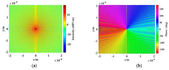
Figure 9.
Transverse electric fields of incident OAM waves by integrating elevation angles with OAM mode l = 1. (a) amplitude distribution (b) phase distribution.
Based on the simulated results presented in Section 3 and Section 4, the following statements can be made: (1) The normalized LRCS from the rough surface for OAM modes and are roughly equal. This is due to the fact that the sign of the OAM mode has a negligible effect on the intensity distribution, with its influence limited only to the phase of the field. (2) The normalized LRCS decreases with an increase in OAM mode. (3) The scattered power is mainly concentrated in the mirror area rough surfaces with small roughness. As the roughness increases, the mirror component decreases, and diffuse reflection dominates. (4) The spatial distribution of LRCS from the Gaussian surface presented in this paper can be used for interpreting OAM high-resolution imaging.
To sum up, the analysis in this article is beneficial for understanding the mechanism of interaction between OAM waves and rough surfaces. Previous studies on the propagation of LG beams encountering rough surfaces in turbulent atmospheres have primarily focused on the phase screen theory, emphasizing the propagation characteristics of light beams rather than the scattering characteristics of targets [11,13]. Combining phase screen theory with the model presented in this paper may provide new ideas for the scattering characteristics of rough targets in turbulent atmospheres. We believe that the scattering model proposed in this paper can provide a theoretical basis for laser radar with OAM mode to detect rough targets and high-resolution imaging.
5. Conclusions
In summary, we proposed a scattering model for a vortex beam from rough surfaces, and numerical results are presented for the backscattering of a rough aluminum surface. In the infrared frequency range, laser radar can detect the fine structures of the rough targets. Therefore, rough surfaces with different roughness parameters were generated and the scattering of vortex waves from these rough surfaces was calculated using the plane wave expansion theory of vortex waves, coordinate system transformations, and the KA method. It can be concluded that various factors, such as incident wave frequency, angle, and roughness parameters, have an impact on the scattering results. Additionally, the evolution angle and the OAM mode also play a significant role in influencing the scattering intensity. The scattering model for the angular and spatial distribution of backscattering LRCS proposed in this paper may provide a theoretical basis for OAM laser radar applications and high-resolution vortex wave imaging.
Author Contributions
Conceptualization, X.Z., X.S. and Z.W.; formal analysis, X.Z.; funding acquisition, X.Z.; investigation, X.Z., X.S. and S.W.; methodology, X.Z. and X.S.; writing—original draft, X.Z.; writing—review and editing, X.Z., X.S. and S.W. All authors have read and agreed to the published version of the manuscript.
Funding
This research was funded by the National Natural Science Foundation of China (No. 62101445) and the Natural Science Foundation of Shaanxi Province, China (No. 2020JQ-843).
Institutional Review Board Statement
Not applicable.
Informed Consent Statement
Not applicable.
Data Availability Statement
Data underlying the results presented in this paper are not publicly available at this time but may be obtained from the authors upon reasonable request.
Acknowledgments
The authors acknowledge the National Natural Science Foundation of China for its support of grant No. 62101445 and the Natural Science Foundation of Shaanxi Province, China, for its support of grant No. 2020JQ-843.
Conflicts of Interest
The authors declare no conflict of interest.
References
- Gibson, G.; Courtial, J.; Padgett, M.J.; Vasnetsov, M.; Pas’ko, V.; Barnett, S.M.; Franke-Arnold, S. Free-space information transfer using light beams carrying orbital angular momentum. Opt. Express 2004, 12, 5448–5456. [Google Scholar] [CrossRef] [PubMed]
- Willner, A.E. OAM Light for Communications. Opt. Photonics News 2021, 32, 34–41. [Google Scholar] [CrossRef]
- Lei, Q.; Gong, H.; Tu, S.; Cai, Y.; Zhao, Q. Experimental Generation of Structured Light Beams through Highly Anisotropic Scattering Media with an Intensity Transmission Matrix Measurement. Photonics 2023, 10, 737. [Google Scholar] [CrossRef]
- Volyar, A.; Abramochkin, E.; Bretsko, M.; Khalilov, S.; Akimova, Y. General Astigmatism of Structured LG Beams: Evolution and Transformations of the OAM Super-Bursts. Photonics 2023, 10, 727. [Google Scholar] [CrossRef]
- Bai, Q.; Tennant, A.; Cano, E.; Allen, B. Experimental circular phased array for generating OAM radio beams. Electron. Lett. 2014, 50, 1414–1415. [Google Scholar] [CrossRef]
- Li, Y.; Zhang, Y.; Wang, D.; Shan, L.; Xia, M.; Zhao, Y. Statistical distribution of the OAM states of Bessel–Gaussian–Schell infrared beams in strong turbulent atmosphere. Infrared Phys. Technol. 2016, 76, 569–573. [Google Scholar] [CrossRef]
- Olivier, A.; Dimitri, M.; Mikael, K.; Brunella, C.; Valentin, C.; Denis, D.; Christian, D.; Bruno, F.C.; Pontus, F.; Julien, G.; et al. Three years of harvest with the vector vortex coronagraph in the thermal infrared. Ground-based and Airborne Instrumentation for Astronomy VI. SPIE 2016, 9908, 182–195. [Google Scholar]
- Wang, Y.; Fang, J.; Zheng, T.; Liang, Y.; Hao, Q.; Wu, E.; Yan, M.; Huang, K.; Zeng, H. Mid-Infrared Single-Photon Edge Enhanced Imaging Based on Nonlinear Vortex Filtering. Laser Photonics Rev. 2021, 15, 2100189. [Google Scholar] [CrossRef]
- Allen, L.; Beijersbergen, M.W.; Spreeuw, R.J.C.; Woerdman, J.P. Orbital angular momentum of light and the transformation of Laguerre-Gaussian laser modes. Phys. Rev. A 1992, 45, 8185. [Google Scholar] [CrossRef] [PubMed]
- Garces-Chavez, V.; Arlt, J.; Dholakia, K.; Volke-Sepulveda, K.; Chavez-Cerda, S. Orbital angular momentum of a high order Bessel light beam. In Summaries of Papers Presented at the Lasers and Electro-Optics. CLEO '02. Technical Diges; IEEE: Long Beach, CA, USA, 2002; Volume 1, pp. 223–224. [Google Scholar]
- Li, Y.; Wang, L.; Gong, L.; Wang, Q. Speckle characteristics of vortex beams scattered from rough targets in turbulent atmosphere. J. Quant. Spectrosc. Radiat. Transf. 2020, 257, 107342. [Google Scholar] [CrossRef]
- Ju, P.; Fan, W.; Gao, W.; Li, Z.; Gao, Q.; Jiang, X.; Zhang, T. Atmospheric Turbulence Effects on the Performance of Orbital Angular Momentum Multiplexed Free-Space Optical Links Using Coherent Beam Combining. Photonics 2023, 10, 634. [Google Scholar] [CrossRef]
- Dong, K.; Cheng, M.; Lavery, M.P.; Geng, S.; Wang, P.; Guo, L. Scattering of partially coherent vortex beam by rough surface in atmospheric turbulence. Opt. Express 2022, 30, 4165–4178. [Google Scholar] [CrossRef] [PubMed]
- Mitri, F.G. Electromagnetic Wave Scattering of a High-Order Bessel Vortex Beam by a Dielectric Sphere. IEEE Trans. Antennas Propag. 2011, 59, 4375–4379. [Google Scholar] [CrossRef]
- Tan, Q.; Wu, Z. Interactions of high-order Bessel vortex beam with a multilayered chiral sphere: Scattering and orbital angular momentum spectrum analysis. J. Quant. Spectrosc. Radiat. Transf. 2018, 217, 363–372. [Google Scholar]
- Es’kin, V.A.; Kudrin, A.V.; Popova, L.L. Scattering of an electromagnetic vortex Bessel beam by a gyrotropic cylinder perpendicular to the beam symmetry axis. In Proceedings of the 2016 Progress in Electromagnetic Research Symposium (PIERS), Shanghai, China, 8–11 August 2016; pp. 3246–3250. [Google Scholar]
- Voti, R.L.; Leahu, G.L.; Gaetani, S.; Sibilia, C.; Violante, V.; Castagna, E.; Bertolotti, M. Light scattering from a rough metal surface: Theory and experiment. J. Opt. Soc. Am. B-Opt. Physics. 2009, 26, 1585–1593. [Google Scholar] [CrossRef]
- Fuks, M. Wave diffraction by a rough boundary of an arbitrary plane-layered medium. IEEE Trans. Antennas Propag. 2001, 49, 630–639. [Google Scholar] [CrossRef]
- Zeng, J.; Chen, K.-S.; Bi, H.; Zhao, T.; Yang, X. A Comprehensive Analysis of Rough Soil Surface Scattering and Emission Predicted by AIEM With Comparison to Numerical Simulations and Experimental Measurements. IEEE Trans. Geosci. Remote Sens. 2017, 55, 1696–1708. [Google Scholar] [CrossRef]
- Jin, M.; Chen, K.-S.; Xie, D. On the Very High-Resolution Radar Image Statistics of the Exponentially Correlated Rough Surface: Experimental and Numerical Studies. Remote Sens. 2018, 10, 1369. [Google Scholar] [CrossRef]
- Zhang, X.; Su, X.; Wu, Z. Analysis of electromagnetic scattering from typical targets for orbital-angular-momentum waves: Theoretical model. IET Microw. Antennas Propag. 2022, 16, 699–708. [Google Scholar] [CrossRef]
- Ulaby, F.T.; Moore, R.K. Microwave Remote Sensing Active and Passive: Radar Remote Sensing and Surface Scattering and Emission Theory. Artech House. 1982, Chap.12, 937–941. [Google Scholar]
- Adachi, S. The Handbook on Optical Constants of Metals: In Tables and Figures; World Scientific Publishing Co. Pte. Ltd.: Singapore, 2012. [Google Scholar]
Disclaimer/Publisher’s Note: The statements, opinions and data contained in all publications are solely those of the individual author(s) and contributor(s) and not of MDPI and/or the editor(s). MDPI and/or the editor(s) disclaim responsibility for any injury to people or property resulting from any ideas, methods, instructions or products referred to in the content. |
© 2023 by the authors. Licensee MDPI, Basel, Switzerland. This article is an open access article distributed under the terms and conditions of the Creative Commons Attribution (CC BY) license (https://creativecommons.org/licenses/by/4.0/).