Article

Research on Resource Allocation Strategy of Indoor Visible Light Communication and Radio Frequency Systems Integrating Orthogonal Frequency-Division Multiple Access Technology

1
Faculty of Automation and Information Engineering, Xi’an University of Technology, Xi’an 710048, China
2
Shaanxi Civil-Military Integration Key Laboratory of Intelligence Collaborative Networks, Xi’an 710126, China
*
Author to whom correspondence should be addressed.
Photonics 2023, 10(9), 1016; https://doi.org/10.3390/photonics10091016
Submission received: 28 July 2023 / Revised: 28 August 2023 / Accepted: 2 September 2023 / Published: 5 September 2023

Abstract

:
Aiming at the problem of resource allocation strategies limiting the system transmission rate in indoor visible light communication and radio frequency (VLC/RF) systems, a new resource allocation method is proposed, and orthogonal frequency-division multiple access (OFDMA) technology is introduced. The capacity of the communication system is effectively increased. In the VLC/RF system model based on OFDMA, the Lyapunov optimization method is used to transform the time averaging problem into a series of single-slot online problems to reduce its computational complexity, the optimization problem is decomposed into three independent subproblems, and the Lagrange relaxation method and convex optimization theory are used to solve the subproblems to maximize the average transmission rate of the system, and the Lyapunov drift is used to ensure the stability of the system. Simulation verifies that the Lyapunov optimization algorithm does not require iteration, which improves the optimization speed to a high extent. The simulation results show that the proposed resource allocation strategy effectively balances the system queue length and transmission rate, improves the average transmission rate of the system to the greatest extent under the premise of ensuring the stability of the system, and compares with other algorithms from the aspects of system stability and transmission rate, which proves the effectiveness of the Lyapunov optimization algorithm.

1. Introduction

Future 6G networks will support data rates of up to 1T bps while also facing the challenge of coping with a large number of mobile devices [1]. However, limited radio spectrum resources make it difficult to meet the needs of explosive massive data transmission, and visible light communication (VLC) combines the advantages of lighting and communication with hundreds of high-frequency bandwidth spectrum that does not require certification [2], alleviating the pressure of insufficient radio frequency (RF) spectrum. In addition, VLC has several advantages, such as high data rate, low power consumption, high security, and small latency [3]. Therefore, VLC is considered to be a promising complementary technology in emerging wireless communications. Data transmission in VLC systems is achieved through intensity modulation on the transmitter side and direct detection on the receiver side, and as with other high-frequency communication technologies, signal propagation at this frequency is highly susceptible to obstacles. Therefore, data transmission between transmitter and receiver in VLC requires a line-of-sight (LOS) path. When there is a non-line-of-sight (NLOS) transmission between the VLC access point (AP) and the user access point, the performance of VLC will degrade sharply. The coverage area of VLC AP is limited, so transmission reliability has become the main concern of the VLC system. Conversely, in the case of NLOS transmission, RF systems can provide a wider coverage area [4]. Therefore, VLC/RF heterogeneous networks have received great attention in recent years, and they have significantly improved in terms of sum rate [5], spectral efficiency [6], power consumption [7], and energy efficiency [8]. However, the introduction of VLC into RF systems faces the problem of access point allocation and resource allocation.
For VLC/RF heterogeneous systems, access point allocation and resource allocation are two important issues to be identified before the user transmits data and are also important factors affecting the transmission rate of the system. At present, most of the research on VLC/RF hybrid systems is mainly focused on power allocation (PA), and there are few related studies on how to reasonably allocate APs for users. Ma et al. [9] developed a two-stage access point selection (APS) method based on a fuzzy logic algorithm to maximize energy efficiency under minimum rate requirements and power constraints. Obeed et al. [10] proposed an iterative algorithm to assign APs to users and derived a new efficient algorithm to find the optimal dual variable through the correlation of dual variables and allocate the power of each AP to connected users to maximize the total capacity of the system and improve the fairness of the system. Pratamay et al. [11] propose a bandwidth aggregation protocol to optimize the throughput of the system. However, under the condition of ensuring system stability, there are still some challenges in how to effectively and dynamically allocate AP, bandwidth, and transmit power and jointly optimize system performance. First, different types of APs can make system design difficult. Generally speaking, binary allocation variables and power allocation make the resource allocation problem become a mixed-integer nonlinear programming (MINP) problem, which is a non-convex problem with high computational complexity. Second, resource allocation should be carried out under random channel conditions; as a joint optimization problem, it is usually necessary to optimize multiple parameters at the same time, so the resource allocation optimization problem is affected by many factors and is difficult to solve.
In this paper, we investigate the performance of VLC/RF systems based on orthogonal frequency-division multiple access (OFDMA) technology. The system consists of multiple VLC APs and one RF AP working together to serve multiple users. Using the OFDMA scheme, resources can be divided into the time domain and frequency domain at the same time, and the divided time–frequency block is called a resource block (RB); for each resource block, the smallest resource block that is indivisible is called a resource unit (RU). OFDMA technology allows multiple users to share all subcarriers of a system, but each subcarrier is limited to one user in the same time slot. If other users need to use this subcarrier, they must queue up in the next time slot, which will reduce system efficiency. Allocating system resources to different users can improve the efficiency and flexibility of the entire communication system rather than just allocating subcarriers or time slots. In addition, OFDMA can flexibly select channels of different frequencies for users and adaptively allocate resources, thereby significantly improving the spectral efficiency and transmission rate of the system. At present, in the field of VLC, OFDMA research mainly focuses on spectral efficiency, and its combination with system transmission rate and stability has not been thoroughly studied. In this paper, in the indoor VLC/RF system based on OFDMA technology, Lyapunov optimization technology is used to transform the time averaging problem into a single time slot problem and divide it into three independent subproblems to solve the optimization problem in a single time slot. The simulation results show that the Lyapunov optimization algorithm does not require iteration, which can greatly improve the optimization speed. In addition, compared with the two traditional resource allocation algorithms, the Lyapunov optimization algorithm can significantly improve the average transmission rate of the system and ensure the stability of the system.

2. System Model

The visible light communication system model is a system that uses visible light communication technology to realize transmission. In this model, the downlink uses VLC and RF technology, and VLC is a complementary technology to RF to transmit information in the form of visible light to the receiver through LED lights. The uplink uses RF technology to transmit the user’s feedback signal back to the transmitter using radio waves. This model takes advantage of the high frequency and large bandwidth of visible light, making data transmission more efficient and reliable. At the same time, by using RF technology as an uplink, users can also easily interact and obtain feedback from the system.

2.1. Downlink Communication

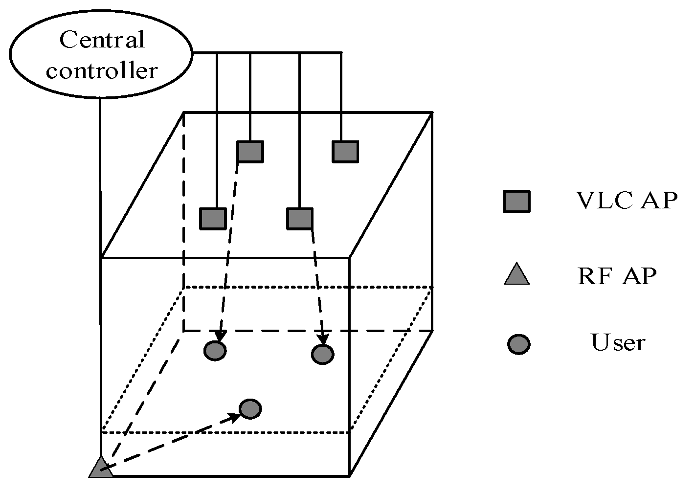
A model of the indoor VLC/RF heterogeneous system is shown in Figure 1. It contains 1 RF AP, l VLC AP, and u users. The VLC AP is mounted on the ceiling, assuming that the RF AP can cover the entire room area. All APs are connected to a central controller that is responsible for collecting user feedback, scheduling, association, and resource allocation. Users are evenly distributed on the receiving plane and are equipped with VLC receivers and RF receivers. The set of APs is L = LVLC + LRF = {0,1,2,···,l}, where LVLC = {1,2,···,l} and LRF = {0} representing the sets of VLC APs and RF APs, respectively. The user set is U = {1,2,···,u}. In this paper, the communication system is divided into T time slots, and the duration of each time slot is ts. Assume that all user locations remain unchanged for a short period. For network selection, the variable a(u,l)(t) is introduced, where a(u,l)(t) = 1 indicates that user u uses APl for access in the time slot t; otherwise, a(u,l)(t) = 0. Since a single user can only be served by one AP in a time slot, the following constraints are obtained
l L a u , l t = 1 , a u , l t 0 , 1 , l

2.1.1. VLC Channel Model

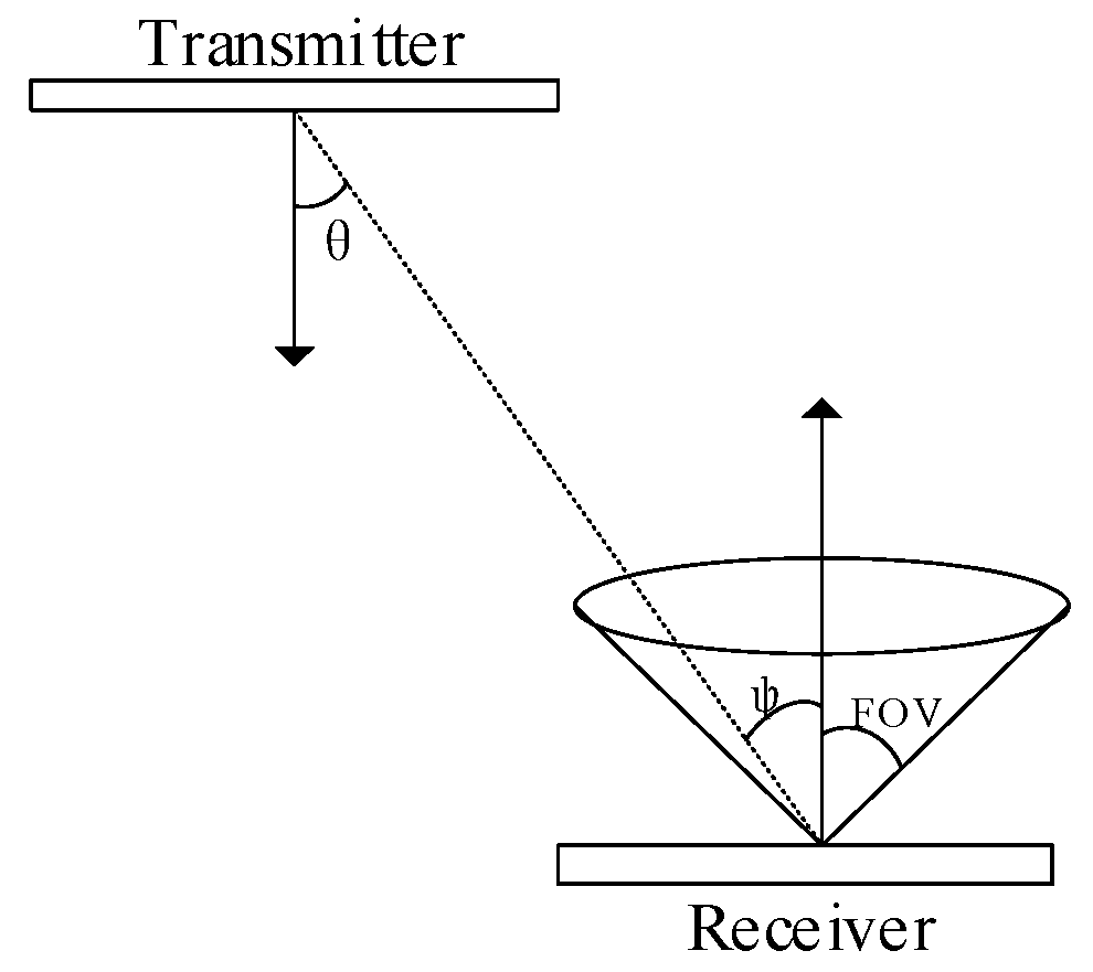
For indoor VLC systems, directional direct view communication links are generally used [12]; that is, the transmitter and receiver of the VLC system are within their respective field of view (FOV) ranges, as shown in Figure 2. For the VLC system studied in this article, the LOS channel gain between VLC APl and user u is
h u , l = m + 1 A p 2 π d 2 cos m θ cos φ T l G l , φ F O V 0 , φ > F O V
where m= −ln2/ln(cos(FOV)) is the Lambertian order, FOV is the half angle of the light source transmitting power, Ap is the effective area of the receiver photodiode, d represents the distance between APl and user u, and θ and φ represent the irradiation angle and incidence angle, respectively. Tl represents the gain of the optical filter, and Gl represents the gain of the concentrator.
In VLC systems, the signal transmission method of intensity modulation and direct detection is adopted. Since the LED operates in its linear region, the output optical power of the modulated signal is proportional to the input voltage, ensuring that the signal transmitted to the receiving end is only positive and solid. In addition, the average emitted electrical power Pe is satisfied with the average emitted optical power Po:
p e = β p o 2
where β is the DC bias factor of VLC AP. Assuming that there are k subcarriers in the VLC system, b k u , l t represents the distribution coefficient of user u with the K subcarriers of VLC APl in time slot t, and b k u , l t = 1 indicates that APl assigns subcarrier k to the user for communication in time slot t; otherwise, b k u , l t = 0 .
The signal-to-noise ratio on the kth subcarrier between user u and VLC APl is
ξ k u , l = ε β p k , o u , l t h k u , l t 2 σ V L C 2 = p k u , l t ε h k u , l t 2 σ V L C 2
where ε represents the photoelectric conversion coefficient received by the user, σ V L C 2 represents the noise power in the VLC channel, and p k , o u , l represents the transmit power of VLC APl to user u on the subcarrier k.
From Shannon’s formula, the effective information transfer rate between VLC APl and user u on the subcarrier k of the time slot t is
ν k u , l t = B V L C log 2 1 + ξ k u , l t
where BVLC is the bandwidth of the subcarrier. Because each subcarrier can only be assigned to one user in a single time slot, there are the following constraints for each subcarrier k:
u U a u , l t b k u , l t 1 , a u , l t 0 , 1 , b k u , l t 0 , 1 , l L V L C
The transmission rate of VLC APl and user u in the t timeslot is
R V L C t = a u , l t ν u , l t = a u , l t k K b k u , l t ν k u , l t
In the timeslot t, the transmit power of VLC APl is
P V L C l t = u U a u , l t P u , l t = u U a u , l t k K b k u , l t p k u , l t
To save power, the upper limit of time average power consumption of VLC APl can be set to
0 lim T 1 T t = 0 T 1 E [ P V L C l t ] < P a v e , V L C
where Pave,VLC represents the maximum average power consumption on VLC APl.

2.1.2. RF Channel Model

RF communication path loss is represented by PL [13] and typically takes the form below
P L d B = A log 10 d u , l + B + C log 10 f c 5 + X
where d(u,l) is the distance between the RF AP and the user; fc is the carrier frequency in GHz; A, B, and C are constants that depend on the propagation model; and X represents the loss of shadow effects in different environments.
RF communicates using OFDM, in which the RF AP uses I resource blocks (RBs). The t time slot, x i u , 0 t , represents the allocation relationship between user u and the ith RB. If x i u , 0 t = 1 , APl assigns RBi to user u; otherwise, x i u , 0 t = 0 . Since there is only one RF AP in a VLC/RF heterogeneous network, channel interference in the RF system can be ignored. Assuming that the RF AP transmits power to user u on RBi of p i u , 0 t , the signal-to-noise ratio between user u and the RF AP is
ξ i u , 0 t = p i u , 0 t g i u , 0 t σ R F 2
where g i u , 0 t = 10 P L d B / 10 represents the RF channel power gain, and σ R F 2 represents the noise power of the RF channel. According to Shannon’s formula, the information transmission rate between the RF AP subchannel i and user u in the time slot t is
ν i u , 0 t = B R F log 2 1 + ξ i u , 0 t
where BRF is the bandwidth of RB. Since each RB can only serve one user in a time slot, it must be satisfied for each RBi
u U a u , 0 t x i u , 0 t 1
Therefore, in the time slot t, the information transfer rate between the RF AP and user u is
R R F t = a u , 0 t ν u , 0 t = a u , 0 t i I x i u , 0 t ν i u , 0 t
The transmit power of the RF AP is derived from the following equation:
P R F 0 t = u U a u , 0 t P u , 0 t = u U a u , 0 t i I x u , 0 t p i u , 0 t
Considering the power condition, the transmitting power should satisfy
P 0 = lim T 1 T t = 0 T 1 E [ P R F 0 t ] < P a v e , R F
where Pave,RF is the maximum average power consumption on the RF AP.

2.2. Uplink Communication

When the downlink successfully receives the signal, it will reply to the sender through the RF transmitter, indicating that the response has been successfully received. Since RF communication is carried out indoors, the Rayleigh fading channel [14] was chosen as the upstream RF communication link channel model. The channel coefficient h of the Rayleigh fading channel obeys a complex Gaussian distribution with a mean of 0 and a variance of σ2, i.e., h~CN(0, σ2), where σ2 = d−α, d represents the RF communication distance, α represents the path fading factor in RF communication, and in the indoor environment, the value is usually taken to be 2~4.
The signal transmitted by the RF transmitter is P R F χ R F t , where PRF is the power of the response signal, χ R F t is the normalized signal, and χ R F t 1 , 1 , E χ R F t 2 = 1 . The signal at the RF receiver can be expressed as
y R F t = P R F h χ R F t + n R F t
where nRF(t) is additive white Gaussian noise and obeys a complex Gaussian distribution with a mean of 0 and a variance of σ R F 2 .

2.3. OFDMA System Model

In this paper, a VLC system model based on OFDMA technology is adopted, which aims to combine optimization objectives with system stability. According to different M-QAM modulation methods, M-ary QAM is adaptively applied to different OFDM subcarriers [15]. A different spectral efficiency (SE) can be achieved on each subcarrier, and Sk is used to represent SE on each subcarrier. The value of Sk depends on the order of M-QAM. The modulation order of M-QAM is adaptively selected by the signal-to-interference plus noise ratio (SINR) between the user and the VLC AP. The relationship between Sk and SINR is determined by the modulation and coding scheme (MCS). The specific value is shown in Table 1. SINR can be expressed as
S I N R f = ε P o H 2 N 0 B + l L ε P o H u , l 2
where N0 represents the noise power spectral density in the VLC channel, B represents the bandwidth of the VLC baseband modulated signal, H represents the channel gain between the VLC AP providing the service and the user u, and H(u,l) represents the channel gain between the non-service VLC AP and the user u, which is regarded as interference noise.
The model uses t = 0,1,2, ···,T as variables by allocating subchannels by time slots, studies the changes in the system in the process of time advancement, and reassigns subchannels. This method fundamentally improves the frequency of system resource allocation so that the system can quickly make optimal allocations in the process of time change. In addition, we use the Lyapunov optimization method for this optimization process to ensure that the system remains stable during changes within t = 0,1,2,···,T. Figure 3 shows the OFDMA system resource allocation model. The dark part represents the scale of resource allocation; for each RB, the smallest block of resources whose indivisibility is called the resource unit (RU), the RU allocates resources in each time slot, and each RU allocation process is independent. This allocation process differs from one-dimensional resource allocation in that in each time slot, the resource allocation problem in OFDMA is degraded from two-dimensional to one-dimensional by setting the integer restriction to b k u t 0 , 1 , and the integer allocation is reduced to a 0–1 integer allocation problem.
In VLC systems, it is generally believed that its channel is time-flat, and there is no fading characteristic during communication. Therefore, the channel state information is constant in each time slot. Suppose that the VLC AP providing the service and the subscriber device subcarrier k can achieve the rate represented by the following equation:
ν k , u t = 2 B S k / K
The transmission rate between the user on subchannel k and the VLC AP providing the service is
R k , u t = b k u t ν k , u t
The transfer rate provided by the VLC AP to user u is
R u t = k K R k , u t
Since a subcarrier can only serve one user per time slot, its distribution coefficient must meet the following constraints:
u U b k u t = 1 , b k u t 0 , 1 , k K

2.4. Queue Model

When the system starts transmitting data, let Qu(t) represent the length of the queue that the system maintains for user u at the beginning of the time slot t, and Du(t) represent the amount of data that user u arrives at the time slot t, which is independently and identically distributed across different time slots [17]. Assuming that the average arrival data rate of user u in the time slot t is γu(t), the following conditions are met for Du(t):
E D u t = γ u t , u U
where γu is a bounded variable that guarantees the stability of the system. According to the above analysis, Qu(t) can be expressed as
Q u t + 1 = Q u t R u t , 0 + + D u t
where Ru(t) represents the amount of data leaving, [x,0]+ = max[x,0]. For each user u, the randomness of Du(t) and the time-varying nature of Ru(t) is given to make the queuing process random. If you only consider maximizing the system transfer rate and ignore the impact of the queue, data will accumulate in the queue during transmission, resulting in the system not operating normally. Therefore, a model of queue stability needs to be established. Generally defined as
lim T 1 T t = 0 T 1 E Q u t <
If all queues in the system are stable, then the VLC communication system will also be stable. This means that the average leave rate in the queue is greater than or equal to the average input rate, and once this condition is met, all data in the queue is sent to its corresponding user.

3. Optimization of the Problem Description

The goal of this article is to achieve the maximum transfer rate while the system remains stable. Within the time slot t, the transmission rate of the entire system can be expressed as
R t = u U R u t = u U l L R u , l t
To achieve the optimization goal of maximizing the average rate of the system, the above function is designed as a time-averaging expression. Therefore, the stochastic optimization problem is formulated as
max   lim T 1 T t = 0 T 1 E R t
s . t   lim T 1 T t = 0 T 1 E Q u t < , u U
l L a u , l t = 1 , a u , l t 0 , 1 , u U , l L
u U a u , 0 t x i u , 0 t 1 , a u , l t 0 , 1 , x i u , 0 t 0 , 1 , u U
0 lim T 1 T t = 0 T 1 E P l t < P l , a v e , P l , a v e = P a v e , R F , i f   l = 0 P a v e , V L C , i f   l = 1 , L
u U a u , l t b k u , l t 1 , a u , l t 0 , 1 ,   b k u , l t 0 , 1 , l L V L C
u U b k u t = 1 , k K
P i u , 0 t 0 , P k u , l t 0 , l L V L C , u U
where (28) is the system stability requirement; (29) ensures that in each time slot, the user can only be served by one AP; (30) ensures that for the RF AP, only one user can be served on each resource block; (31) represents the average power budget constraint of each AP; (32) ensures that each subchannel of the VLC AP can only serve one user; (33) ensures that for one VLC AP, each subcarrier can only be assigned to one user at a time; and (34) indicates that the transmit power of all APs is not negative and meets the actual conditions.
There are long-term constraints in the above problem, and to effectively handle long-term time-averaged power constraints, virtual queues in Lyapunov optimization can be used to convert (31) into queue stability constraints [18]. Virtual queues are defined as Z(t) ≜ {Z1(t),···, Zl(t),···,ZL(t)},Zl(t) and evolved as follows:
Z l t + 1 = max Z l t P l , a v e , 0 + P l t
It should be noted that there is no actual queue data in queue Zl(t), which is only proposed to satisfy the constraint (31). If the virtual queue Zl(t) is average-rate stable, constraint (31) automatically holds [19].
Suppose the order vector of queue length in the system is Θ(t) = [Q(t), Z(t)]. The Lyapunov function is defined as a measure of the total queue length for each time slot t, denoted by the following equation:
L Θ t = 1 2 u U l L Q u 2 t + 1 2 l L Z l 2 t
In each time slot, the conditional Lyapunov drift is defined as
Δ Θ t E L Θ t + 1 L Θ t Θ t
It can be observed that at each time slot, the Lyapunov function can control the final value of the Lyapunov drift by adjusting the final queue length. The purpose of this paper is to maximize the average system transfer rate, and the drift-penalty function term is defined as follows:
Δ Θ t V E R t Θ t
where V is a non-negative constant parameter used to balance drift with reward. When the V value increases, the system assigns a higher priority to maximize the transmission rate, that is, sacrifice the queue length; when the V value decreases, the system prioritizes the queue length to maintain the stability of the system.
For each period, for a given V ≥ 0, the upper bound of the drift-penalty function for any possible Θ(t) is
Δ Θ t V E R t Θ t = E L Θ t + 1 L Θ t Θ t V u U l L E R u , l t Θ t C + u U l L E Q u t D u t a u , l t ν u , l t Θ t + l L E Z l t P l t P l , a v e Θ t
where C is a constant satisfying the following conditions:
C 1 2 u U E D u 2 t + R u 2 t Θ t + 1 2 l L E P l 2 t + P l , a v e 2 Θ t
According to the Lyapunov optimization method [20], the network utility is optimized by minimizing the drift-penalty function term to minimize the queue length. Therefore, Problem (35) can be transformed into minimizing the upper bound of the Lyapunov drift-penalty function on each time slot, which is expressed as
  min   u U l L Q u t D u t a u , l t ν u , l t + l L Z l t P l t P l , a v e V u U l L a u , l t ν u , l t   s . t   ( 29 )   ( 30 )   ( 31 )   ( 32 )
The reformulated optimization problem (41) is a constrained mixed-integer programming problem where a u , l t takes integer values, and p i u , 0 t and p k u , l t take continuous values. Therefore, the optimization problem (41) is decomposed into three relatively independent subproblems, and the corresponding optimization algorithm is proposed.

3.1. AP Allocation

The AP allocation variables a(u,l)(t) in the system can be obtained by solving the following subproblems:
  min   u U l L Q u t D u t a u , l t ν u , l t V u U l L a u , l t ν u , l t   s . t   l L a u , l t = 1 , a u , l t 0 , 1 , u U , l L
It can be seen from (42) that the network selection between different users is independent. Therefore, Problem (42) can be decomposed into U subproblems, and each subproblem is
  max l L a u , l t e u , l t s . t   l L a u , l t = 1 , a u , l t 0 , 1 , u U , l L
where e(u,l)(t) = (Qu(t) + V)v(u,l). Since (43) is a linear optimization problem, its solution is as follows:
a u , l t = 1 ,   l = arg max l e u , l t , 0 < l < L , 0 ,   o t h e r w i s e .
Under the above network selection strategy, e(u,l)(t) can be regarded as the congestion cost of the AP serving the user within the time slot t. Then, Equation (44) ensures that the user can connect to the AP with the smallest congestion cost.

3.2. VLC AP Joint Subcarrier and Power Allocation

According to the access point allocation variable a(t) obtained from subproblem (42), the joint subcarrier and power allocation subproblem in the VLC system can be solved continuously:
  max   u U l L V L C a u , l t ν u , l t Q u t + V Z l t P l t P a v e , V L C t s . t   u U a u , l t b k u , l t 1 , a u , l t 0 , 1 , b k u , l t 0 , 1 , u U , p k u , l t 0 , u U
Since the selection of subcarriers is independent among different VLC APs, Problem (45) can be decomposed into |LVLC| subproblems, and each subproblem is expressed as
  max   u U B V L C log 2 1 + p k u , l t ε h k u , l t 2 σ V L C 2 Q u t + V Z l t P l t P a v e , V L C t s . t   u U a u , l t b k u , l t 1 , a u , l t 0 , 1 , b k u , l t 0 , 1 , u U l , p k u , l t 0 , u U l
where Ul denotes the set of users connected to VLC AP. The VLC joint subcarrier and power allocation problem is a hybrid combinatorial optimization problem. To solve this problem, the Lagrange relaxation method can be used to transform the original integer programming mixed problem into a convex optimization problem. Relaxing b k u , l t 0 , 1 to b ˜ k u , l t 0 , 1 , the optimization problem is reformulated as
max   k K u U l b ˜ k u , l t Q u t + V B V L C log 2 1 + p k u , l t ε h k u , l t 2 b ˜ k u , l t σ V L C 2 Z l t k K u U p k u , l t P a v e , V L C t   s . t u U l b ˜ k u , l t 1 , u U l ,   0 b ˜ k u , l t 1 , u U l , p k u , l t 0 , u U l .
Since k K u U l b ˜ k u , l t Q u t V B V L C log 2 1 + p k u , l t ε h k u , l t 2 b ˜ k u , l t σ V L C 2 is a convex function of b ˜ k u , l t and p k u , l t , think of it as a linear function of log 2 1 + p k u , l t ε h k u , l t 2 σ V L C 2 . Therefore, the given optimization problem is a K × |Ul| linear combination of convex functions. Let L P = k K u U l b ˜ k u , l t Q u t + V B V L C log 2 1 + p k u , l t ε h k u , l t 2 b ˜ k u , l t σ V L C 2 Z l t k K u U p k u , l t be the objective function and find the partial derivative of   p k u , l t for L P :
L P p k u , l t = b ˜ k u , l t Q u t + V B V L C ε h k u , l t 2 b ˜ k u , l t σ V L C 2 + p k u , l t ε h k u , l t 2 ln 2 Z l t
According to the Karush–Kuhn–Tucker (KKT) conditions, the system can achieve optimal power allocation when the following conditions are satisfied:
L P k K u U l μ k u p k u , l t p k u , l t = b ˜ k u , l t Q u t + V B V L C ε h k u , l t 2 b ˜ k u , l t σ V L C 2 + p k u , l t ε h k u , l t 2 ln 2
Z l t μ k u = 0
μ k u p k u , l t = 0 , k , u
μ k u 0 , k , u
where μ k u is the multiplier for constructing the Lagrange function. To ensure that (51) holds, then μ k u = 0 or p k u , l t = 0 . The partial derivative of Formula (49) is 0, and the relationship between p k u , l t and b ˜ k u , l t can be obtained.
p k u , l t = Q u t + V B V L C Z l t ln 2 σ V L C 2 ε h k u , l t 2 + b ˜ k u , l t
The result of power allocation will be used to obtain the subcarrier allocation. Substituting Equation (53) into Equation L P , we obtain
L P = k K u U L k u P b ˜ k u , l t
where
L k u P = Q u t + V B V L C log 2 1 + Q u t + V B V L C Z l t ln 2 σ V L C 2 ε h k u , l t 2 + ε h k u , l t 2 σ V L C 2 Z l t Q u t + V B V L C Z l t ln 2 σ V L C 2 ε h k u , l t 2 +
Obviously, Problem (54) is a linear assignment problem, which can be decomposed into k subproblems. Each subproblem is represented by the following equation:
L k P = u U L k u P b ˜ k u , l t
For subcarrier k, the optimal allocation is to obtain the user with the maximum L k u P , and the solution can be obtained.
b ˜ k u , l t = 1 ,   u = arg max u L k u P , u U l , L k u P > 0 , 0 ,   o t h e r w i s e .

3.3. RF AP Joint Resource Block and Power Allocation

In RF communication systems, the RF AP joint resource block and power allocation subproblem can be expressed as
  max   u U 0 a u , 0 t Q u t + V Z 0 t P 0 t P a v e , R F t s . t u U 0 x i u , 0 t 1 , a u , 0 t 0 , 1 , x i u , 0 t 0 , 1 , u U 0 p i u , 0 t 0 , u U 0
It can be seen from the above problems that the joint RB and power allocation problems are independent of each other on different time slots t. Therefore, the objective function of Problem (58) is a function of discrete variables x i u , 0 t and continuous variables p i u , 0 t , so the problem is also a mixed-integer nonlinear convex optimization problem, which can be solved by the Lagrange relaxation method. Firstly, x i u , 0 t is relaxed to the continuous interval [0, 1], and a new variable x ˜ i u , 0 t is defined. Problem (58) can be rewritten as
  max   i I u U 0 x ˜ i u , 0 t Q u t + V B R F log 2 1 + p i u , 0 t g i u , 0 t x ˜ i u , 0 t σ R F 2 Z 0 t i I u U 0 p i u , 0 t s . t u U 0 x ˜ i u , 0 t 1 , x ˜ i u , 0 t 0 , 1 , u U 0 p i u , 0 t 0 , u U 0
Let the objective function L P = i I u U 0 x ˜ i u , 0 t Q u t + V B R F log 2 1 + p i u , 0 t g i u , 0 t x ˜ i u , 0 t σ R F 2 Z 0 t i I u U 0 p i u , 0 t and calculate the partial derivative of p i u , 0 t :
L P p i u , 0 t = x ˜ i u , 0 t Q u t + V B R F g i u , 0 t x ˜ i u , 0 t σ R F 2 + p i u , 0 t g i u , 0 t ln 2 Z 0 t
According to the KKT conditions, the system achieves the optimal power allocation when the following conditions are satisfied.
L P i I u U 0 μ i u p i u , 0 t p i u , 0 t = x ˜ i u , 0 t Q u t + V B R F g i u , 0 t x ˜ i u , 0 t σ R F 2 + p i u , 0 t g i u , 0 t ln 2
Z 0 t μ i u = 0
μ i u p i u , 0 t = 0 , i , u
μ i u 0 , i , u
where μ i u is the multiplier for constructing the Lagrange function. To ensure that Equation (63) holds, then μ i u = 0 or p i u , l t = 0 . When the partial derivative of Equation (61) is 0, the relationship between p i u , l t and x ˜ i u , l t can be obtained.
p i u , 0 t = Q u t + V B R F Z 0 t ln 2 σ R F 2 g i u , 0 t + x ˜ i u , 0 t
The result of power allocation will be used for the allocation of RF resource blocks. Substituting Equation (63) into L P , we can obtain
L P = i I u U 0 L i u P x ˜ i u , 0 t
where
L i u P = a i u , 0 t Q u t + V B R F log 2 1 + a i u , 0 t x ˜ i u , 0 t Q u t + V B R F Z 0 t ln 2 B R F σ R F 2 g i u , 0 t + g i u , 0 t B R F σ R F 2 Z 0 t a i u , 0 t x ˜ i u , 0 t Q u t + V B R F Z 0 t ln 2 B R F σ R F 2 g i u , 0 t +
Obviously, Problem (66) is also a linear assignment problem. Therefore, it can be decomposed into i subproblems, and each subproblem is expressed as
L i P = u U L i u P x ˜ i u , 0 t
The objective of this problem is to maximize the L i P of all subcarriers. Therefore, for all subcarriers i, the optimal allocation is to select the user with the largest L i P .
x ˜ i u , l t = 1 ,   u = arg max u L i u P , u U , 0 ,   o t h e r w i s e .

4. Analysis of Algorithm Simulation Results

In this section, we analyze the simulation results of the Lyapunov optimization algorithm and verify the performance of the proposed indoor VLC/RF system resource allocation scheme with OFDMA technology. Assuming that the room size is 8 m × 8 m × 3 m, as shown in Figure 1, 4 VLC APs are installed on the ceiling, which are located at (3,2,3), (5,2,3), (3,5,3) and (5,5,3), respectively, and each AP has 25 subcarriers. The RF AP is located at (0,0,0), and it has four RBs. Other key simulation parameters of the system are shown in Table 2.
To simplify the simulation, we consider the normalized spectrum bandwidth of VLC AP and RF AP, traffic arrival for each user device follows the Poisson distribution, the average traffic arrival rate is expressed in γ, the traffic arrival rate and RF channel conditions remain constant within a time slot and change on the time slot boundary, γ specific values will be given in the simulation. Since the spectral bandwidth is normalized and the unit of transmitted data volume is set to package, assuming that the average communication rate of the VLC AP subcarrier in the system is five packages and the average communication rate of an RF AP single RB is three packages, the average traffic arrival rate is limited to less than five packages.
Figure 4a shows the relationship between the penalty parameter V and the average queue length Q under different average traffic arrival rates γ. It can be observed that the Q value in the system increases with the increase in V, and as the average traffic arrival rate γ increases, the average queue length Q also increases. Figure 4b shows the change in penalty parameter V and average transmission rate R under different average traffic arrival rates γ. It can be seen that the average transfer rate R increases with the increase in the V value because when the V value increases, the optimization degree of the algorithm on the average transmission rate increases. In addition, as the average traffic arrival rate γ value increases, the growth rate of the average transmission rate slows down because when the γ value is small, the amount of data transmitted by the system can meet the amount of data arrived. When the γ value is large, the system rejects additional packets to ensure data queue stability. From Little’s theorem [21], since the average transmission delay is proportional to the average queue length, the average queue length can be used to describe the average delay, and in the Lyapunov optimization process, selecting the appropriate control parameter V can balance the relationship between the average transmission rate and the average transmission delay.
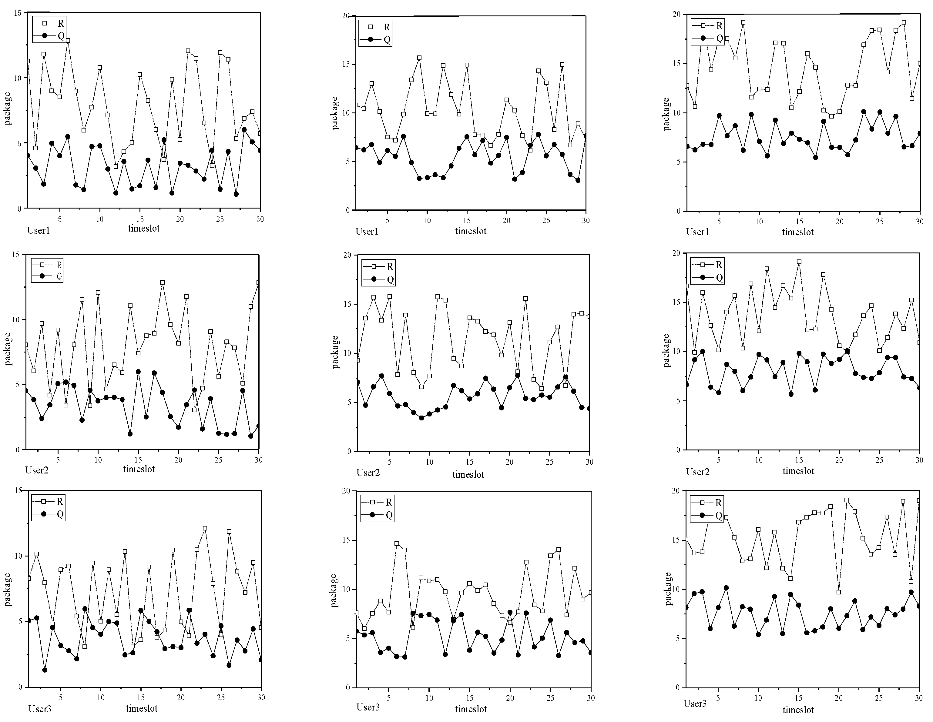
In addition, the instantaneous change in the system is simulated. Assuming that the user’s position is changing in each time slot, the instantaneous change in the user on 30 time slots is given. Figure 5a–c depict the instantaneous transfer rate and queue length change for four users in the system when the penalty parameter V is valued at 50, 150, and 300. It can be observed that for each user, as the length of the user’s queue increases, so does the data transfer rate for that user. This is because the Lyapunov optimization algorithm makes the system provide a higher transfer rate to reduce the buffer queue, thus ensuring the stability of the entire system. Another conclusion is that the queue length in the system is longer when V = 300 is longer than when V = 50 and 150.
Figure 6 shows the change in average queue length Q and average transfer rate R with the number of users in the system using different algorithms. The Lyapunov optimization algorithm was compared with the minimized distance resource allocation (MD-RA) algorithm and the best channel state information resource allocation (BCSI-RA) algorithm [22]. Obviously, from Figure 6a, it can be seen that with the increase in the number of users, the average queue length of the system gradually increases compared to the MD-RA algorithm and BCSI-RA algorithm, the queue length under the Lyapunov optimization algorithm is smaller, and the growth rate is the slower, indicating that the system has better stability when using the Lyapunov algorithm. It can be seen from Figure 6b that as the number of users in the system increases, the average transmission rate also increases, and the average transmission rate under the Lyapunov optimization algorithm is significantly higher than that of the MD-RA algorithm and BCSI-RA algorithm, and the average transmission rate increases significantly when the number of users is greater than six.
Figure 7 shows the average queue length vs. average transfer rate as a function of the number of users, taking into account the interrupt probability, and compares the performance of the system using the three algorithms. Suppose p represents the probability of LOS availability in VLC systems and generates a random number between 0 and 1; if this number is greater than p, then the LOS of VLC AP is available. Otherwise, LOS is not available. This study shows that the Lyapunov optimization algorithm can achieve higher transmission rates while ensuring that the average queue length of the system is low; that is, the algorithm can provide better system performance.
As shown in Figure 8, as the penalty parameter V value increases, the average queue length Q and the average transmission rate R in the uplink communication link under different numbers of users also increase. This is because increasing the penalty parameter will cause the system to allocate more resources to the user, thereby optimizing the performance of the system. At the same time, as can be seen from Figure 8a, as the number of users increases, the queue backlog in the system accelerates because the increase in the number of users leads to a decrease in the uplink communication rate, which affects the performance of the entire system. To balance the relationship between queue length and transmission rate, the appropriate penalty parameter V can be selected to make the system communication more stable. Figure 8b also shows that the average transfer rate increases gradually as the number of users increases. Changes in both Q and R values indicate a decrease in the communication rate of the upstream RF link. This is because, with limited spectrum resources and base station processing power, users must share resources, resulting in network congestion and transmission delays, which in turn reduce the communication rate of the entire system.
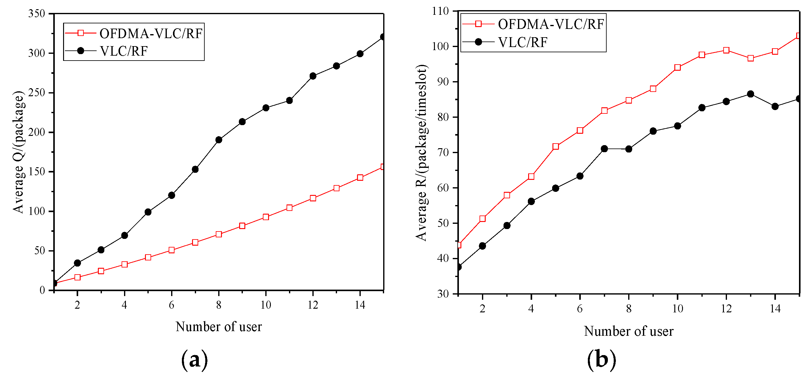
Figure 9 shows the average queue length Q and average transmission rate R in the OFDMA-VLC/RF system and VLC/RF system as a function of the number of users. As shown in Figure 9a, the queue extrusion speed in the VLC/RF system using OFDMA technology is significantly slower than that in the VLC/RF system without OFDMA technology, and the Q value change in the OFDMA-VLC/RF system is relatively stable, indicating that the system has strong stability. It can be observed from Figure 9b that as the number of users increases, the average transmission rate of the system gradually increases, and when the number of users increases to 15, the average transmission rate of the OFDMA-VLC/RF system increases by 17 packages compared with the VLC/RF system, because the use of OFDMA technology increases the capacity of the entire communication system, thereby increasing the system transmission rate.

5. Conclusions

In this paper, the resource allocation problem in indoor OFDMA-VLC/RF systems is studied, and an allocation strategy based on the Lyapunov optimization algorithm is proposed. The purpose of this study is to solve the resource allocation problem by maximizing the average transmission rate of the system under the constraints of system stability and the average power budget:
(1) To find the optimal resource allocation strategy, we formulate a random optimization problem, which considers the stability constraints and average power budget of the system and takes the average transmission rate of the system as the optimization goal.
(2) Using the Lyapunov optimization algorithm, the stochastic optimization problem is decomposed into three independent subproblems, and their optimal solutions are given respectively. Through simulation, the effectiveness of the proposed resource allocation strategy is verified. The results show that this strategy significantly improves the average transmission rate of the system while maintaining the stability of the system. This means that our approach can improve system performance by making more efficient use of limited resources in indoor OFDMA-VLC/RF systems.
This study has important practical significance for improving the performance of indoor wireless communication systems and provides a valuable reference for further research. In the future, the results can meet the communication needs between IoT devices and provide efficient communication services. In the smart home system, this technology can realize the interconnection between devices. In addition, the technology can also support real-time interaction and immersive experience of virtual reality (VR) and augmented reality (AR) technologies, providing high-speed and low-latency communication services. In the field of health care, the resource allocation strategy based on this technology can provide high-speed and reliable communication services, support data transmission between medical devices and telemedicine services, and improve the efficiency and quality of health care. In short, the resource allocation strategy of indoor VLC/RF systems based on OFDMA technology and the Lyapunov optimization algorithm has the characteristics of high speed, high efficiency, and reliability in communication applications in various fields, which will promote the development of future communication technology.
Author Contributions

Conceptualization, X.K.; methodology, X.K. and Y.X.; software, Y.X.; validation, X.K., Y.X., H.Q. and J.L.; formal analysis, X.K.; investigation, Y.X.; resources, X.K. and Y.X.; data curation, X.K. and Y.X.; writing—original draft preparation, X.K. and Y.X.; writing—review and editing, X.K. and Y.X. All authors have read and agreed to the published version of the manuscript.

Funding

This research was funded by the Key Industrial Innovation Chain Project of Shaanxi Province of the funder, grant number 2017ZDCXL-GY-06-01, and the General Project of the National Natural Science Foundation of China of the funder, grant number 61377080.

Institutional Review Board Statement

This study did not require ethical approval.

Informed Consent Statement

This study did not require ethical approval.

Data Availability Statement

The data that support the findings of this study are available from the corresponding author upon reasonable request.

Conflicts of Interest

The authors declare no conflict of interest.

References

  1. Zhou, Y.; Liu, L.; Wang, L.; Hui, N.; Cui, X.; Wu, J.; Peng, Y.; Qi, Y.; Xing, C. Service-aware 6G: An intelligent and open network based on the convergence of communication, computing, and caching. Digit. Commun. Netw. 2020, 6, 253–260. [Google Scholar] [CrossRef]
  2. Ke, X.; Ding, D. Wireless Optical Communication, 2nd ed.; Science Press: Beijing, China, 2022. [Google Scholar]
  3. Arfaoui, M.A.; Soltani, M.D.; Tavakkolnia, I.; Ghrayeb, A.; Majid Safari, M.; Assi, C.; Haas, H. Physical layer security for visible light communication systems: A survey. IEEE Commun. Surv. Tutor. 2020, 22, 1887–1908. [Google Scholar] [CrossRef]
  4. Wu, W.H.; Zhou, F.; Yang, Q.H. Adaptive Network Resource Optimization for Heterogeneous VLC/RF Wireless Networks. IEEE Trans. Commun. 2018, 66, 5568–5581. [Google Scholar] [CrossRef]
  5. Papanikolaou, V.K.; Diamantoulakis, P.D.; Sofotasios, P.C.; Muhaidat, S.; Karagiannidis, G.K. On optimal resource allocation for hybrid VLC/RF networks with common backhaul. IEEE Trans. Cogn. Commun. Netw. 2020, 6, 352–365. [Google Scholar] [CrossRef]
  6. Abdelhady, A.M.; Amin, O.; Chaaban, A.; Shihada, B.; Alouini, M.S. Downlink resource allocation for dynamic TDMA-based VLC systems. IEEE Trans. Wirel. Commun. 2019, 18, 108–120. [Google Scholar] [CrossRef]
  7. Kashef, M.; Abdallah, M.; Al-Dhahir, N. Transmit power optimization for a hybrid PLC/VLC/RF communication system. IEEE Trans. Green Commun. Netw. 2018, 2, 234–245. [Google Scholar] [CrossRef]
  8. Aboagye, S.; Ibrahim, A.; Ngatched, T.M.N.; Ndjiongue, A.R.; Dobre, O.A. Design of Energy Efficient Hybrid VLC/RF/PLC Communication System for Indoor Networks. IEEE Wirel. Commun. Lett. 2020, 9, 143–147. [Google Scholar] [CrossRef]
  9. Ma, S.; Zhang, F.; Li, H.Z.; Mohamed, S.A.; Li, S.Y. Aggregated VLC-RF Systems: Achievable Rates, Optimal Power Allocation, and Energy Efficiency. IEEE Trans. Wirel. Commun. 2020, 19, 7265–7278. [Google Scholar] [CrossRef]
  10. Obeed, M.; Salhab, A.M.; Zummo, S.A.; Alouini, M. Joint optimization of power allocation and load balancing for hybrid VLC/RF networks. J. Opt. Commun. Netw. 2018, 10, 553–562. [Google Scholar] [CrossRef]
  11. Pratama, Y.S.M.; Choi, K.W. Bandwidth Aggregation Protocol and Throughput-Optimal Scheduler for Hybrid RF and Visible Light Communication Systems. IEEE Access 2018, 6, 32173–32187. [Google Scholar] [CrossRef]
  12. Kahn, J.M.; Barry, J.R. Wireless infrared communications. Proc. IEEE 1997, 85, 265–298. [Google Scholar] [CrossRef]
  13. Kashef, M.; Ismail, M.; Abdallah, M.; Mohamed; Qaraqe, K.A.; Serpedin, E. Energy Efficient Resource Allocation for Mixed RF/VLC Heterogeneous Wireless Networks. IEEE J. Sel. Areas Commun. 2016, 34, 883–893. [Google Scholar] [CrossRef]
  14. Dakhli, C.M.; Zayani, R.; Belkacem, B.O.; Bouallegue, R. Theoretical analysis and compensation for the joint effects of HPA nonlinearity and RF crosstalk in VBLAST MIMO-OFDM systems over Rayleigh fading channel. EURASIP J. Wirel. Commun. Netw. 2014, 2014, 61. [Google Scholar] [CrossRef]
  15. Hammouda, M.; Vegni, A.M.; Haas, H.; Peissig, J. Resource Allocation and Interference Management in OFDMA-based VLC Networks. Phys. Commun. 2018, 31, 169–180. [Google Scholar] [CrossRef]
  16. Armstrong, J.; Schmidt, B.J.C. Comparison of Asymmetrically Clipped Optical OFDM and DC-Biased Optical OFDM in AWGN. IEEE Commun. Lett. 2008, 12, 343–345. [Google Scholar] [CrossRef]
  17. Wang, Y.H.; He, Y.H.; Xu, C.; Zhou, Z.Y.; Pervaiz, H. Joint rate control and power allocation for low-latency reliable D2D-based relay network. EURASIP J. Wirel. Commun. Netw. 2019, 2019, 111. [Google Scholar] [CrossRef]
  18. Bao, W.; Chen, H.; Li, Y.; Vucetic, B. Joint rate control and power allocation for non-orthogonal multiple access systems. IEEE J. Sel. Areas Commun. 2017, 35, 2798–2811. [Google Scholar] [CrossRef]
  19. Guo, Y.; Yang, Q.; Kwak, K.S.; Fu, F. Quality-oriented rate control and resource allocation in time-varying OFDMA networks. IEEE Trans. Veh. Technol. 2017, 66, 2324–2338. [Google Scholar] [CrossRef]
  20. Zhang, R.; Claussen, H.; Haas, H.; Hanzo, L. Energy efficient visible light communications relying on amorphous cells. IEEE J. Sel. Areas Commun. 2016, 34, 894–906. [Google Scholar] [CrossRef]
  21. Valencia-Estrada, J.C.; García-Marquez, J.; Chassagne, L.; Topsu, S. Catadioptric interfaces for designing VLC antennae. Appl. Opt. 2017, 56, 7559. [Google Scholar] [CrossRef] [PubMed]
  22. AlQahtani, S.A.; Alhassany, M. Comparing Different LTE Scheduling Schemes. In Proceedings of the IEEE 9th International Wireless Communications and Mobile Computing Conference (IWCMC 2013), Sardinia, Italy, 1–5 July 2013; pp. 264–269. [Google Scholar]
Figure 1. Indoor VLC/RF heterogeneous system model.
Photonics 10 01016 g001
Figure 2. Indoor VLC downlink LOS link model.
Photonics 10 01016 g002
Figure 3. OFDMA system resource allocation model.
Photonics 10 01016 g003
Figure 4. (a) Relationship between average queue length Q and control parameter V; (b) relationship between average transmission rate R and control parameter V.
Photonics 10 01016 g004
Figure 5. The instantaneous transmission rate and queue length of each user change under different V values. (a) V = 50; (b) V = 150; (c) V = 300.
Photonics 10 01016 g005aPhotonics 10 01016 g005b
Figure 6. (a) The relationship between the average queue length Q and the number of users under the three algorithms; (b) the relationship between the average transmission rate R and the number of users under the three algorithms.
Photonics 10 01016 g006
Figure 7. (a) The relationship between the average queue length Q of the outage probability and the number of users is considered under the three algorithms; (b) the relationship between the average transmission rate R of the outage probability and the number of users is considered under the three algorithms.
Photonics 10 01016 g007
Figure 8. (a) The relationship between the average queue length Q and the penalty parameter V under different numbers of users in the uplink RF link; (b) the relationship between the average transmission rate R and the penalty parameter V of the uplink RF link under different number of users.
Photonics 10 01016 g008
Figure 9. The performance of the OFDMA-VLC/RF system is compared with the VLC/RF system: (a) comparison of the average queue length Q of the system; (b) comparison of the average transmission rate R of the system.
Photonics 10 01016 g009
Table 1. The relationship between SINR and modulation, coding rate, and SE [16].
SINRmin [dB]Modulation ModeEncoding RateSE [bit/Hz]
1QPSK0.440.8770
3QPSK0.591.1758
516QAM0.371.4766
816QAM0.481.9141
916QAM0.602.4063
1164QAM0.452.7305
1264QAM0.553.3223
1464QAM0.653.9023
1664QAM0.754.5234
1864QAM0.855.1152
2064QAM0.935.5547
Table 2. Simulation parameters.
ParameterMeaningValue
L × W × HRoom size8 m × 8 m × 3 m
Φ1/2Power half angle70°
FOVField of view60°
nNumber of LEDs5
PaveLED transmit power4 W
ApThe effective receiving area of PD1 cm2
TlOptical filter gain1
GlConcentrator gain1
εPhotoelectric conversion factor0.52 A/W
nreThe refractive index of PD1.5
Disclaimer/Publisher’s Note: The statements, opinions and data contained in all publications are solely those of the individual author(s) and contributor(s) and not of MDPI and/or the editor(s). MDPI and/or the editor(s) disclaim responsibility for any injury to people or property resulting from any ideas, methods, instructions or products referred to in the content.