Article

Investigating the Role of Temperature in Laser Assisted Chemical Bath Deposition for ZnO Growth for Photodetector Application

1
School of Physics, Universiti Sains Malaysia, Gelugor 11800, Malaysia
2
Department of Physics and Chemistry, Northern Boarder University, Rafha 91911, Saudi Arabia
3
Department of Optics Techniques, Dijlah University College, Baghdad 10081, Iraq
4
MLab, STI Unit, The Abdus Salam International Centre for Theoretical Physics, Strada Costiera 11, 34151 Trieste, Italy
5
Physics Department, College of Science, Imam Mohammad Ibn Saud Islamic University (IMSIU), Riyadh 13318, Saudi Arabia
*
Authors to whom correspondence should be addressed.
Photonics 2023, 10(8), 910; https://doi.org/10.3390/photonics10080910
Submission received: 28 June 2023 / Revised: 23 July 2023 / Accepted: 2 August 2023 / Published: 7 August 2023
(This article belongs to the Special Issue Photodetector Materials and Optoelectronic Devices)

Abstract

:
ZnO microrods (ZnO-MRs) have unique properties that make them highly attractive for applications such as optoelectronics, electronics, and sensors. This work demonstrates the successful synthesis of high-quality ZnO-MRs using a laser-assisted chemical bath deposition method. The optimal growth temperature for high-quality ZnO-MRs was found to be 61.10 °C, considerably lower than that required for conventional chemical methods. Various characterization techniques, including X-ray diffraction (XRD), field emission scanning electron microscopy (FESEM), energy Dispersive X-ray (EDX), and UV-Vis spectrometry, confirmed the structural and optical properties of the synthesized ZnO-MRs. The UV detection potentialities of the fabricated ZnO-MRs were investigated. All samples exhibited good UV detection capabilities with the sample grown at 61.10 °C showing the best performance with fast response and recovery times of 1.260 s and 1.398 s, respectively. These findings hold immense potential for developing more efficient methods for synthesizing ZnO-MRs for use in various applications.

1. Introduction

Zinc oxide (ZnO) is an intrinsically n-type II–VI compound semiconductor, partly due to natural doping by interstitial zinc (Zn) atom or oxygen (O) vacancy and naturally crystallizes in the hexagonal wurtzite structure [1]. Due to its wide direct band gap of 3.37 eV and large exciton binding energy of 60 meV, ZnO exhibits excellent properties such as good thermal mechanical stability and unique electronic-optical properties [2]. Besides that, it has other significant properties such as unique crystalline orientation, high-optical gain, fast response and slow electron-hole recombination. ZnO is also regarded as a potential studied material in recent decade amongst various 1D semiconductor nanomaterials. ZnO in 1D nanostructure can be used in diverse applications such as nano-lasers [3], light-emitting diodes [4], photodetectors [5], solar cells [6], field-effect transistors [7], photocatalysts [8], etc. Several fabrication methods, such as chemical bath deposition [9], sol-gel method [10], electrochemical deposition [11] and hydrothermal [12], have been used to grow 1D ZnO nanostructures on different substrate materials. In fact, most of these aqueous solution synthesis methods, especially chemical bath deposition (CBD) and hydrothermal, require a longer growth time and well-controlled environment. Hence, the laser-assisted chemical bath deposition (LA-CBD) method is introduced as it possesses high performance and is the most effective method for growing 1D ZnO nanostructures. Samer et al. reported that by using LA-CBD, the growth of ZnO nanotubes (NTs) between metallic Fe pads on a glass substrate was successful [13]. When the ZnO NTs were illuminated with 380 nm light, the UV photodetector demonstrated a repeatable and steady on-off photocurrent values [13,14].
LA-CBD is an attractive option due to its rapid fabrication, ease of use, affordability, low operating temperature (below 100 °C), and ability to produce high-quality crystals. Additionally, incorporating a continuous wave (CW) laser during bath deposition enhances the growth of ZnO nanostructures by improving their morphology and electrical conductivity [14,15]. Consequently, compared with CBD, LA-CBD is promising as it greatly reduces the growth time as mentioned in previous work. In LA-CBD, deposition parameters govern ZnO structures, which then significantly influences the performance of the UV photodetector, which has ZnO as the active area. In fact, solution temperature in LA-CBD directly controls the size, density distribution and shape of ZnO. This work emphasizes the fabrication of a Ni/ZnO UV photodetector based on vertically aligned ZnO microrods using LA-CBD. We focused on growing ZnO on a tiny glass substrate with an area of about 1 cm2 in order to fulfill the conventional photodetector’s size. The grown ZnO structures at different solution temperatures using LA-CBD are characterized by its surface morphology, structural properties, elemental composition, and optical properties. By assessing its electronic properties, the performance of the ZnO structure on the tiny glass substrate as a UV photodetector is also discussed.

2. Materials and Methods

2.1. Preparation of Substrates

A microscopic glass was cut into several pieces. Each has a dimension of 1 cm length × 1 cm width × 0.1 cm thickness. These glass substrates were cleaned with 3% decon 90 and 97% DI water at 60 °C for 30 min, followed by 100% of deionized water at 60 °C for another 30 min twice. The cleaned substrates were dried in an oven at 200 °C for 10 min. Based on some previous reports, it was found that using decon 90 can actually clean the glass slides effectively as acetone and ethanol. Besides that, decon 90 is non-phosphate, non-flammable, and has no pungent smell compared to acetone and ethanol.

2.2. Deposition of Nickel (Ni) Pads

Radio-frequency (RF) magnetron sputtering (Auto HHV 500 Sputter Coater) was employed to deposit Ni metal on the glass substrates as electrode pads. A high vacuum of 4.91 × 10⁻⁵ mbar was obtained using a Diffusion Pump with Rotary Pump. The chamber’s working pressure was kept constant at 6.76 × 10⁻³ mbar. RF power of 150 W was applied to the electrodes, and the film was deposited for 30 min. After 30 min, the chamber was left cooling, and the substrates with deposited Ni film with a thickness of 150 nm were taken out. A narrow slit was cut along the thin Ni film on each glass substrate to remove the Ni metal.

2.3. Preparation of Precursor Solution

A specific precursor solution, which will be used for growing ZnO-NRs, was prepared. Firstly, a 1.098 g of zinc acetate dehydrate [Zn (CH3COO)2 2H2O] Sigma-Aldrich (CAS Number 5970-45-6) and a 0.701 g of Hexamethylenetetramine (HMTA) [(CH2)6N4] Sigma Aldrich (CAS Number 100-97-0) were measured, respectively. All chemicals were obtained from Sigma Aldrich without additional purification. Both solids were dissolved in 100 mL of deionized (DI) water by swirling the solution magnetically at room temperature for 1 h to obtain an evenly growing solution with a concentration of 50 mM. A small amount of diethanolamine (DEA) is suggested to be added into the cloudy precursor solution to turn the solution clear.

2.4. Growth of ZnO by Continuous Wave Laser-Assisted Chemical Bath Deposition

In the continuous wave (CW) laser-assisted CBD method (CW LA-CBD), the heater and laser were used simultaneously. Since the fabrication process required a short period, the heater was first turned on to preheat for around 5 min. A Ni-coated glass substrate was then inserted horizontally into a small glass bottle. The small bottle was then filled with 5 drops of precursor solution, and the cap of the bottle was closed tightly. The filled bottle was placed on a heater. A few ceramic pieces were placed below the bottle cap to prevent the plastic cap from melting during heating, as shown in Figure 1. The laser source was turned on. The blue laser light at a power density of 0.16 W/cm2 and with peak wavelength of 441.3 nm was irradiated at the slit between two Ni pads for 30 min. The average temperature of the solution was around 51.11 °C, measured by an infrared-thermometer. A ZnO spot were grown in the slit and on a part of the Ni edge, resulting in a metallic Ni contact on Ni pads. The sample was then carefully removed from the bottle. Finally, to eliminate any residual substances on the sample, we performed a thorough rinse using DI water and subsequently dried it using compressed nitrogen gas. The fabrication was then repeated for different average temperatures of precursor solution such as 61.10 °C and 69.10 °C. For higher temperatures, the heater was preheated for a longer time, in order to make the precursor solutions able to reach the required temperatures and maintain the temperature stability.

2.5. Characterization and Photodetection Analysis of the Produced Samples

FESEM, FEI Nova NanoSEM 450 was utilized to investigate the surface morphology and growth structure of the fabricated ZnO-MRs. An EDX spectrometer was used to identify presence of elements and measure elemental composition of specific materials in a sample. The X-ray Diffractometer (Rigaku, Japan) was used to study the prepared samples’ phase and identify their structures. By using a Cu-K radiation course with wavelength of 1.542 Å, the samples were tested in the range (2θ) from 20° to 80°. The joint committee on powder diffraction standards (CPDS) used in analyzing ZnO was under 01–079–0206. Cary 5000 UV-Vis-NIR spectroscopy was used to measure the absorbance of fabricated ZnO. The I-V properties of the generated UV PDs and photocurrents response based on ZnO-NRs were investigated using a Keithely 2400 current source unit linked to a computer for data processing.

3. Results and Discussion

3.1. Zinc Oxide Spot: Stereo Microscopy

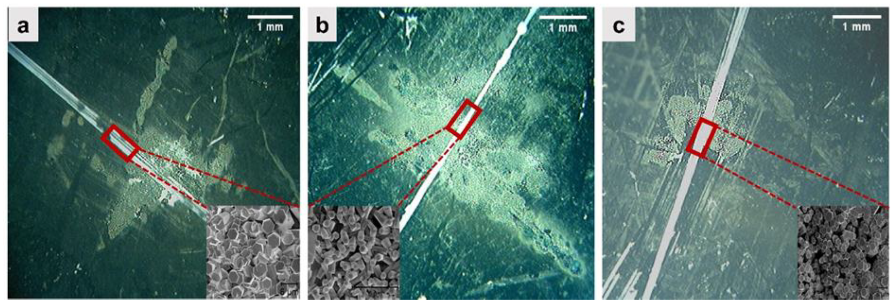
Figure 2 depicts the ZnO spots that formed on the glass substrates during LA-CBD at different solution temperatures under microscopy. It can be seen that the spots are irregular in shape. This is due to the non-uniform heat distribution in and around the slit. During LA-CBD, the incident laser photons were absorbed and converted to heat by the Ni metal nanoparticles located at the area between the slit. This energy conversion process is due to the surface plasmon resonance effect generated by Ni nanoparticles when illuminated by laser light [16]. Hence, at different solutions temperatures, ZnO spots successfully formed at the area where laser light illuminated. The average area of the ZnO spots and the width of the slits were measured using ImageJ software and are summarized in Table 1. The ZnO spot formed at a solution temperature of 69.10 °C has the most significant growth area, while the growth areas of ZnO at solution temperatures of 51.11 °C and 61.10 °C are comparatively small. At higher solution temperatures, such as 69.10 °C, the area ZnO spot became larger and went beyond the laser coverage area. This might be attributed to the fact that the temperature outside the laser coverage area is already sufficient to grow ZnO microrods that can be visually identified.

3.2. Characterization of ZnO Microrods: Electron Microscopy

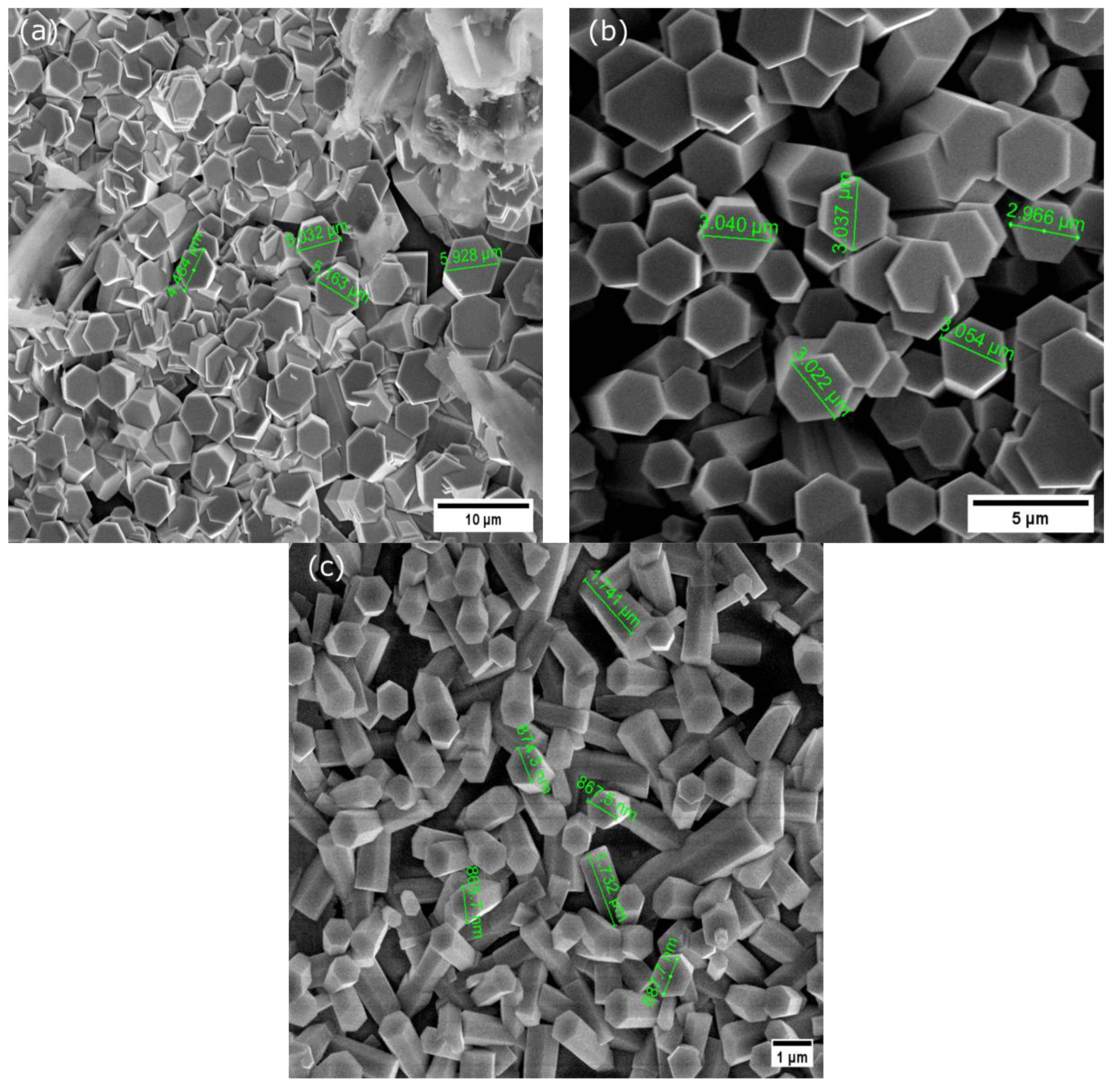
FESEM (FEI Nova NanoSEM) was utilized to investigate the surface morphology and growth structure of the fabricated ZnO-MRs. Figure 3 demonstrates the lateral structure of ZnO-MRs, which were grown on the microscopic glass by LA-CBD at different solution temperatures. It is observed that at a higher solution temperature such as 69.10 °C, a non-uniform, low density and random orientation of ZnO-MRs in small hexagonal grain size formed over the slit between Ni contact, as shown in Figure 3c,b, and shows that the morphology of ZnO-MRs was improved to vertical well alignment, uniform density distribution and bigger hexagonal grain sizes when depositing under lower solution temperatures, especially at 61.10 °C.
Surprisingly, decreasing the solution temperature results in a significant change of the ZnO rod’s lateral diameter. However, at lower solution temperatures, such as 51.11 °C, the hexagonal ZnO-MRs were yet formed uniformly, as shown in Figure 3a. This is because ZnO nucleates and grows relatively slower at this temperature [17]. Moreover, at 69.10 °C, due to the presence of laser at a spot between the Ni metal contact, the spot area reached a higher temperature, which went beyond 69.10 °C. This high temperature increases the nucleation rate of ZnO, which in turn reduces its rod diameter due to the solubility of ZnO with temperature [18]. Each ZnO mean rod diameter was measured and calculated using ImageJ software from the top view of the FESEM images. The size distributions of ZnO-MRs at different solution temperatures were then plotted in histograms, presented in Figure 4. The deviations of each result are shown in Table 2. Interestingly, a discernible trend could be observed for the mean diameter of ZnO-MRs at three different solution temperatures. The solution temperature of 51.1 °C forms the largest mean diameter of ZnO (4.17 μm), followed by 61.10 °C (2.89 μm), and finally 69.10 °C (0.86 μm). This signifies that solution temperature strongly correlates with the grain size of ZnO formed by LA-CBD. The mean grain size of each ZnO-MRs by LA-CBD agrees with previous studies [18,19].

3.3. Characterization of ZnO Microrods: Chemical Composition

Table 3 shows the elemental compositions of grown ZnO-MRs at different solution temperatures using EDX analysis. The presence of ZnO is confirmed through the EDX analysis and coincides with its composition. Furthermore, the grown samples are confirmed to be pure ZnO, as no impurities or substrate are found. The quantitative analysis indicates that the final samples at different solution temperatures have their predicted molar ratio of Zn and O close to the estimated value (1:1). Similar findings have been obtained in previous literature [20].
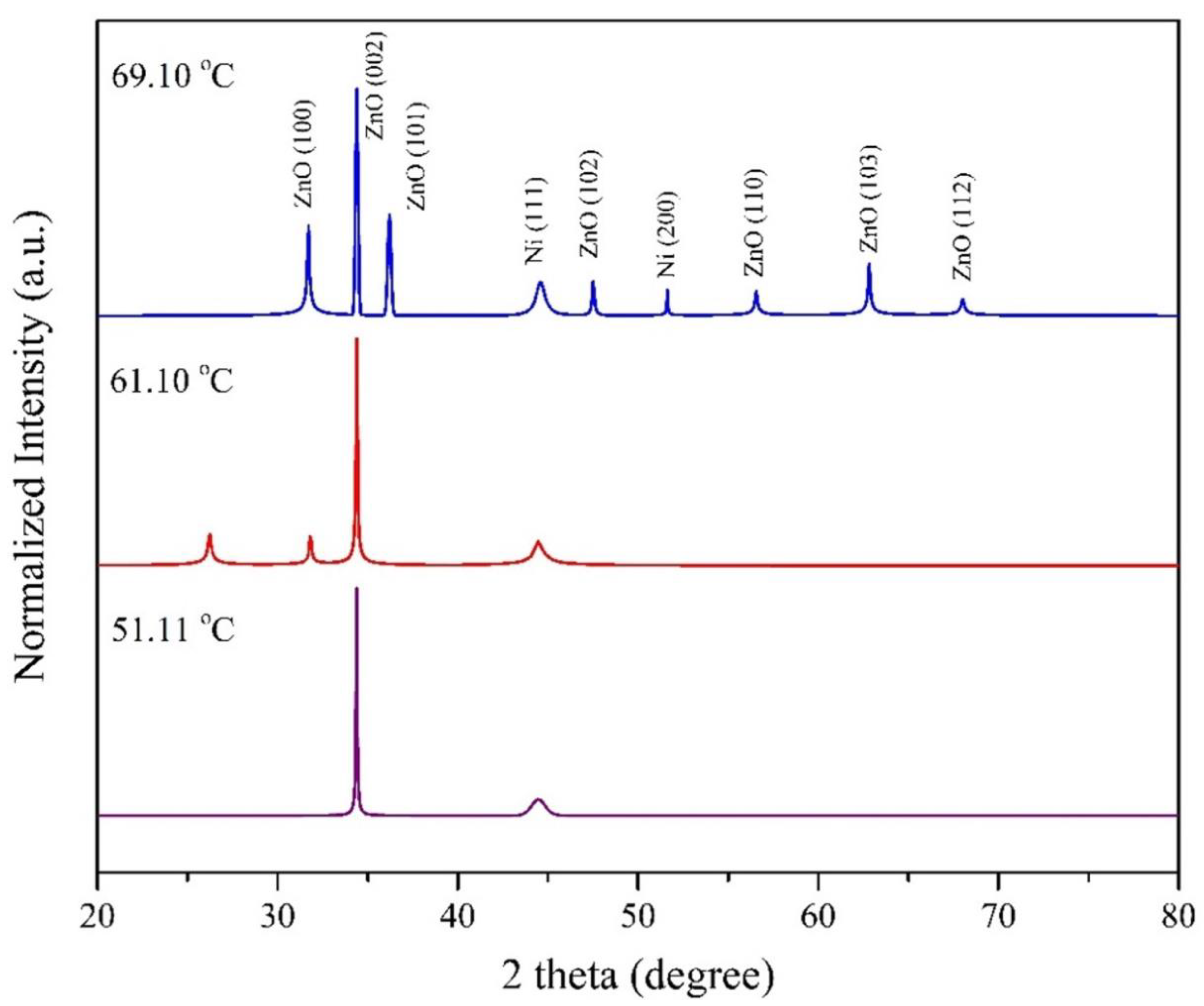
The X-ray diffractometer (XRD) was used to study the prepared samples’ phase and identify their structures. All XRD diffraction peaks were indexed as wurtzite hexagonal phase of ZnO, according to JCPDS cards No. 01-079-0206 [21]. The crystalline sizes, the dislocation density, δ, which is the inverse of the crystallite size, the hexagonal structure of ZnO, the lattice constants, a, b, and c, the lattice strains of ZnO nanostructures synthesized on the glass substrate along the a-xis and c-axis, εa and εc, are calculated based on reported known equations [21,22,23,24]. Figure 5 illustrates the XRD results of fabricated ZnO at different growth temperatures. It is found that when the solution temperature was 69.10 °C, the sample had quite a number of detected peaks which were located at 31.73°, 34.41°, 36.21°, 47.49°, 56.57°, 62.83° and 68.04°, which attributed to (100), (002), (101), (102), (110), (103) and (112) planes of fabricated ZnO-MRs. Conversely, when the solution temperature decreased to 61.10 °C, the number of detected peaks decreased to two, located at 31.80° and 34.41°, which attributed to (100) and (002) planes of ZnO. When the solution temperature was 51.11 °C, there was only one detected peak at 34.39°, which attributed to the (002) plane of ZnO. Among all the diffraction peaks, (002) is the highest, hence, it is dominant for all the samples. The sharp, narrow, and strong ZnO (002) indicates that the wurtzite hexagonal ZnO-MRs preferably grow along the c-axis, which is perpendicular to the glass substrate. This is because the (002) orientation has the lowest surface free energy as compared to other peak directions, such as the (100) and (101) planes. The presence of other diffraction peaks, such as (100), (101), (102), (110), (103), and (112), indicate that the ZnO microrods at a solution temperature of 69.10 °C not only nucleate on the polar c-planes of the crystallite but also on the other nonpolar plane directions [25]. Therefore, it is suggested that the growth of ZnO changed from a single crystalline structure to a polycrystalline structure when the growth temperature increased. Also, the observation of the Ni (200) peak being visible at the highest temperature can be attributed to the effect of induced defects on the crystallographic planes, which results from the temperature-dependent crystalline defects. The presence of defects can influence the formation and exposure of specific crystallographic planes. At higher temperatures, the kinetics of defect formation and migration may vary between samples, resulting in different levels of defect-induced crystallographic changes. The structural properties of ZnO microrods, such as peak position (θ), FWHM (β), interplanar spacing (Å), crystalline size (Å), lattice constants (a and c), and the internal strains (εa and εc) along the diffraction peak (002) at different solution temperatures, are recorded in Table 4. The FWHM at (002) plane of ZnO decreases with the solution temperature from 69.10 °C to 61.10 °C, signifying the improvement in the crystal quality. The minimum value of FWHM is then observed when ZnO-MRs are formed at 61.10 °C during LA-CBD. The interplanar spacing of each ZnO-MRs at different solution temperatures along (002) peaks are almost the same due to the similar diffraction angles. The average crystallite size of ZnO-MRs increases from 543.15 Å to 1376.493 Å with decreasing solution temperature from 69.10 °C to 61.10 °C.
According to the Dedye–Scherrer formula, crystallite size is inversely proportional to FWHM value. The reduction of FWHM values with decreasing solution temperature results in the increase of crystallite sizes in (002) orientation. The maximum value of average crystallite size is then observed when the solution temperature reached 61.10 °C during LA-CBD. This indicates that ZnO-MRs that are grown along the c-axis at 61.10 °C have the largest grain size. Additionally, the difference of strains (εa) and (εc), as presented in Table 4, is due to the variation of interplanar spacing and shows how substantial the mismatch is between ZnO crystal growth and the glass substrate. The strain values along the ZnO-MRs (002) are almost same for all the solution temperatures. A positive value of strain is associated with tensile strain, representing the expansion in the lattice constant while a negative value of strain is related with compressive strain specifying contraction in the lattice contraction [26]. Hence, ZnO lattice was being expanded along c-axis and was being contracted along a-axis. The results are in good agreement with the observation in the previous XRD pattern where the (002) peak is the highest among all samples [13,15,20]. The dislocation density continuously decreases when decreasing the solution temperature from 69.10 °C to 61.10 °C. This signifies that the number of defects in ZnO crystal growth reduces at lower solution temperatures. Moreover, as mentioned in the literature review, the dislocation density is inversely proportional to the square of the crystallite size, hence it suggests that crystal structure, which has a lower number of defects, is able to grow in larger grain sizes.

3.4. Characterization of ZnO-Microrods: Optical Profile

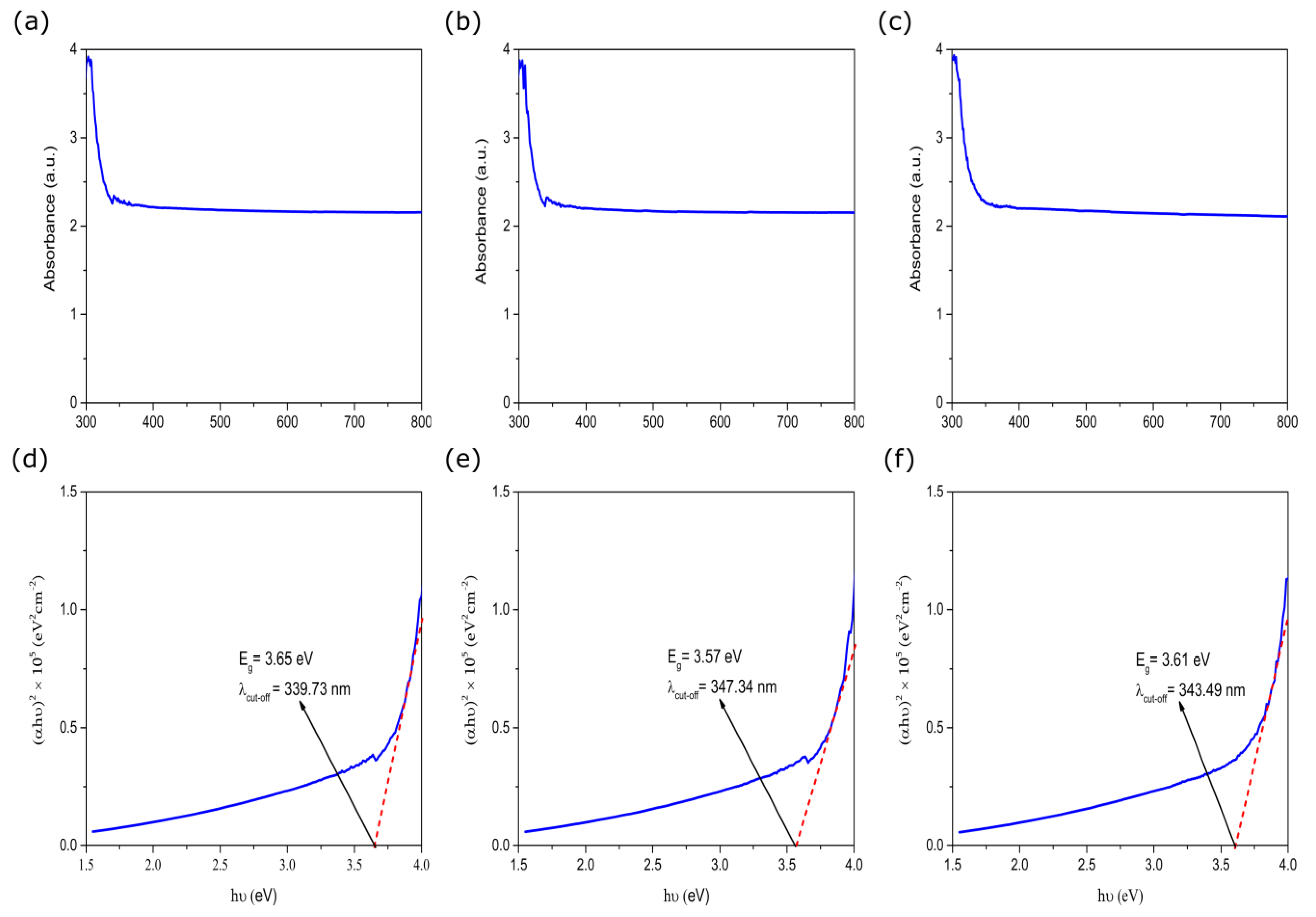
Figure 6a–c presents the collected absorption spectra of the samples. From there, noises are observed at wavelength ranges from 200 nm to 280 nm. It is because the substrate used in this work was microscopic glass, and it was also chosen as the reference cell in the UV-Vis spectrophotometer. It is known that glass absorbs UV-C light with wavelength ranges from 100 nm to 280 nm. For that, almost all the UV-C light with wavelengths within 200 nm to 280 nm was absorbed by the glass substrate after the light penetrated the ZnO spot above it. Due to that, the detected signal was extremely low and was challenging to be identified by the spectrophotometer. Furthermore, based on Figure 6d–f, the cut-off absorption edges for hexagonal wurtzite ZnO that formed at different solution temperatures such as 51.11 °C, 61.10 °C and 69.10 °C are 339.73 nm, 347.34 nm, and 343.49 nm, respectively. When compared to bulk ZnO with a cut-off wavelength of 365 nm, the absorption peaks have blue-shifted. This work agrees with the previous work [27]. This is because the area surrounding the ZnO spot was not able to be fully covered by the anti-reflective plate, so some light is absorbed and transmitted to the detector, resulting inaccurate results. However, if the anti-reflective plate has too small a circular hole and is able to cover some parts of the irregular ZnO spot, almost all the light will be absorbed by the plate and the left very least light will be able to transmit. Hence, a very weak signal is detected.

3.5. UV Photoconductive Characterization

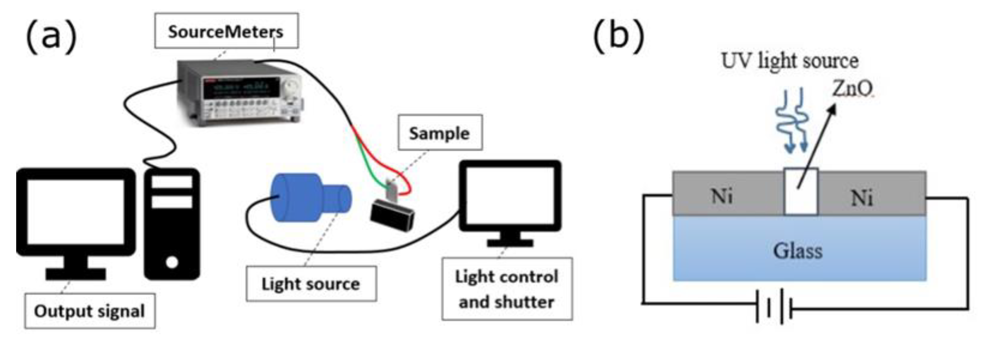
The I-V properties and photocurrents response of ZnO-NRs were investigated as depicted Figure 7a. Figure 7b shows the structure layer of this work. A metal contact was established by growing ZnO-MRs in the slit between the Ni pads and the deposition of Ni contact pads. The active area of each ZnO spot formed at 51.11 °C, 61.10 °C and 69.10 °C is 3.072 mm2, 1.175 mm2, and 6.657 mm2. A two-point probe was used to characterize the photoelectrical characteristics of UV photodetector-based ZnO-MRs. The light source for the ultraviolet light illumination was a light emitting diode (LED) at room temperature and ambient environment. For the electrical parameters and UV photoconductive characterization are detailed description is in Section S1.
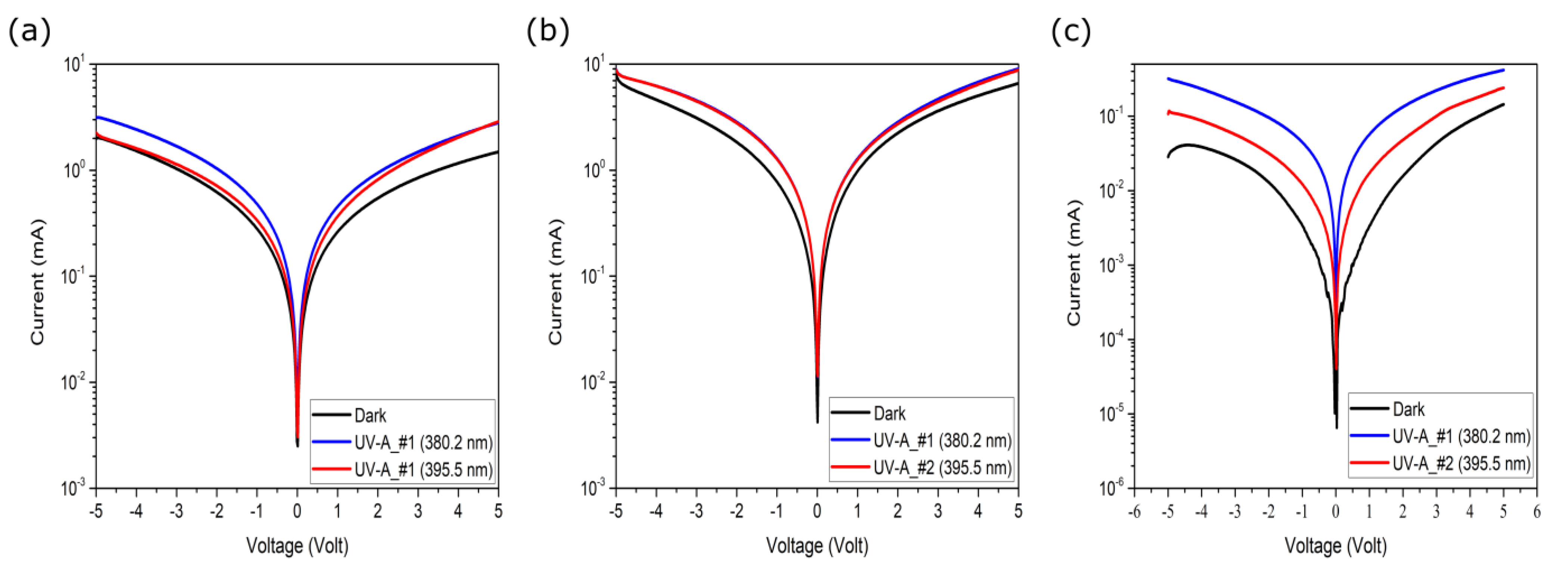
Figure 8 displays the I-V characteristic of ZnO-MRs in the dark and under the illumination of UV-A with two different peak wavelengths such as 380.2 nm with a power density of 18.661 mW/cm2 and 395.5 nm with a power density of 12.021 mW/cm2. This was conducted in the range of −5 to +5 V. In addition, the I-V characteristics of ZnO-MRs fabricated at different solution temperatures, such as 51.11 °C, 61.10 °C, and 69.10 °C, were studied. Since the work function of ZnO is 4.45 eV, which is lower than the work function of Ni metal of 5.05 eV, a Schottky junction is predicted to form. In this work, all three I-V characteristics curves, as shown in Figure 8, demonstrate a Schottky behavior. This indicates that the experimental results in this work agree with the theoretical prediction. The capacity of ZnO-MRs to detect UV light was investigated merely by collecting their electrical response under UV illumination as a proof of concept, and it was discovered that clumps of ZnO-MRs do indeed function as a bridge between two Ni pads. From Figure 8a–c, it is observed that the current rises when increasing the forward bias voltage in response to UV light. When 5 V is applied as a forward voltage, the dark current was 0.149 mA, 6.587 mA, 0.144 mA, the net photocurrent for UV-A with a wavelength of 380.2 nm was 1.313 mA, 2.453 mA, 0.273 mA and the net photocurrent for UV-A with a wavelength of 396 nm was 1.389 mA, 2.203 mA, 0.097 mA for ZnO-MRs formed at 51.11 °C, 61.10 °C and 69.10 °C, respectively. The photoelectric effect of ZnO-MRs can explain the generation of photocurrent. Besides that, the Ni metal, which acts as contact electrodes between the slit, can rapidly capture the photoelectrons generated in ZnO-MRs thin film to the external electronic circuit. However, a sizeable inverse current may be attributed to hole diffusions from ZnO bulk to the interface [28]. Moreover, the fabricated ZnO at a solution temperature of 61.10 °C has a relatively larger photocurrent than the other two. From our point of view, this significant difference affirms that ZnO-MRs, with bigger crystallite sizes, are uniformly aligned along the c-axis and have a larger surface area to volume ratio for effective UV light absorption. On the contrary, at solution temperatures of 51.11°C and 69.10 °C, the irregular hexagonal shape and non-uniform alignment of grown ZnO along the c-axis leads to the weaker absorption of incident UV photons at the ZnO nanostructure surface; this reduces the number of photo-generated carriers, resulting in much lower photocurrent.

3.6. Photocurrent-Time Characteristics

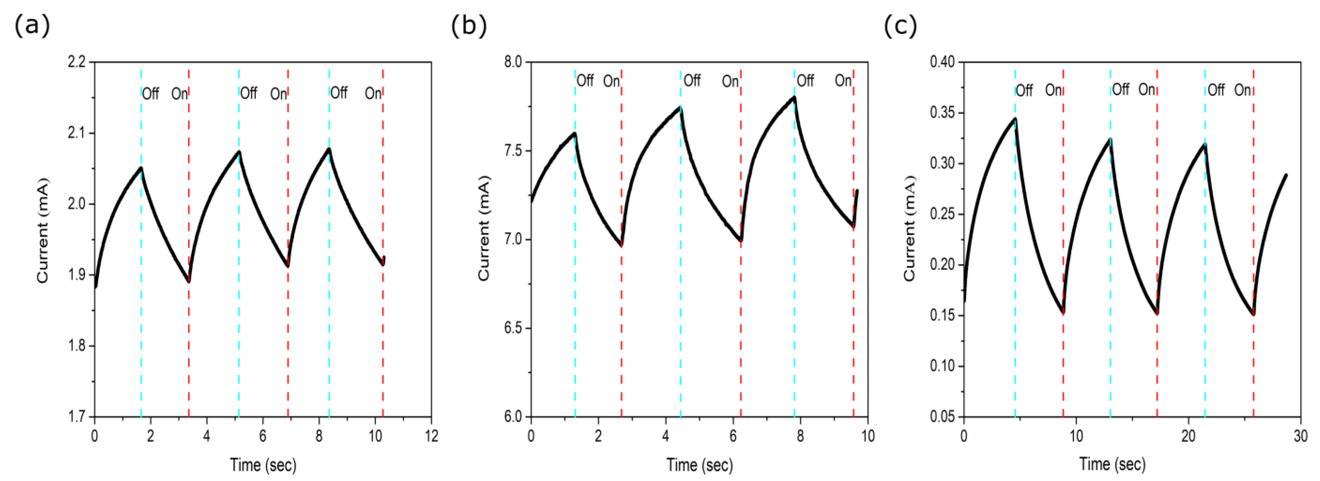
Figure 9a–c depicts the photocurrent response of ZnO-MRs-based photodetectors under UV-A illumination with a peak wavelength of 380.2 nm. The UV light intensity remained constant at 18.661 mW/cm2 throughout the whole testing to better compare among three photodetectors. Each test was carried out at 5 V bias and consisted of three cycles of UV light in on/off states. Based on Figure 9, all the UV photodetectors based on ZnO-MRs have repeatable properties. The incident photons with energy higher than the bandgap of ZnO were absorbed and excited the electrons, leaving the positively-charged holes in the valence band producing electron-hole pairs. When the device was connected to an external electric circuit, the electron-hole pairs were separated by an external electric field and finally collected by the Ni electrodes, resulting in the flow of current in the external circuit. Any changes in the circuit current due to the changes in photon intensity were detected and presented as an output signal [29]. The rise and fall of the current peak over time, which indicates the photo-response of ZnO, can be explained based on a hole-trapping mechanism that happens during the oxygen adsorption and desorption process under UV illumination and the recombination of electron-hole pairs.
Figure 10 depicts the temporal fluctuation of the measured normalized photocurrent in an enlarged view. When the UV light source is turned on, the measured current rises rapidly, then gradually declines when the illumination is turned off. The response times of the photodetector, such as rise time and decay time, were estimated and shown in Figure 10. The decay time of the three samples is longer than the rising period. In fact, decay time represents the time taken for excess holes generated through photoexcitation to recombine with the electrons. Longer decay time can then be ascribed to the longer recombination time between electron-hole pairs due to the trapped holes. Point defects that exist within intrinsic ZnO crystal lattices, such as O vacancies and Zn interstitial, become the hole-trapping deep levels and capture some photogenerated holes. Subsequently, these can be re-emitted back to the valence band, as shown in Figure 10 [30].
Besides that, from our point of view, the amount of O ions on the surface may also capture the holes before they recombine with the electron [31]. Hence, both situations result in longer recombination between holes and electrons, thus prolonging the decay time. Moreover, the photodetector based on ZnO grown at 69.10 °C shows a more obvious longer rise and fall time compared to the other two. Besides the poor alignment of ZnO-NRs over the substrate that was stated previously, the result could also be explained by the presence of grain boundaries since ZnO was synthesized in a nanorod structure. NRs have trapping states at grain boundaries, resulting in photogenerated carriers traveling in longer diffusion paths [32]. Hence, the electrons are trapped and de-trapped continuously before being collected by the electrode, thus prolonging the photodetector’s rise and decay time [33]. Table 5 summarizes some performance metrics of the fabricated UV photodetector based on ZnO-MRs and some earlier publications. From there, the performance of our photodetector is comparable to that in other research works, in addition to having a more straightforward device configuration and easy preparation method with a shorter time consumed since the laser was used to assist heating in CBD.

4. Conclusions

This work highlights the synthesis, characterization, and optoelectronic device’s application of ZnO micro-nanostructures arrays grown on glass substrate using CW LA-CBD. ZnO-MRs were successfully formed between Ni pads in a slot on the flat glass substrate. ZnO’s growth area could be reduced to a few millimeters square or even smaller, indicating the utility of the laser in CBD, which can accurately control the growth size and position of nanomaterial grown on a tiny substrate. Uniformly aligned and sharp hexagonal-shaped ZnO appeared under a solution temperature of 61.10 °C in 30 min of LA-CBD. ZnO-MRs UV photodetector formed on glass substrate at 61.10°C showed fast response time and recovery time, such as 1.260 s and 1.398 s, compared to the other two samples grown at 51.11 °C and 69.10 °C. Additionally, the device showed good responsivity and remarkable stability over time.

Supplementary Materials

The following supporting information can be downloaded at: https://www.mdpi.com/2304-6732/10/8/910/s1, Section S1: UV Photoconductive Characterization. References [38,39] are cited in the Supplementary Materials.

Author Contributions

Conceptualization, N.M.A. and L.X.Q.; methodology, L.X.Q.; software, L.X.Q.; validation, A.S.A., H.C. and A.M.N.; formal analysis, L.X.Q.; investigation, N.M.A. and L.X.Q.; resources, K.H.I. and O.A.A.; data curation, L.X.Q.; writing—original draft preparation, L.X.Q. and N.M.A.; writing—review and editing, A.M.B. and H.C.; visualization, N.M.A.; supervision, N.M.A.; project administration, O.A.A.; funding acquisition, K.H.I. All authors have read and agreed to the published version of the manuscript.

Funding

The authors extend their appreciation to the Deanship of Scientific Research at Imam Mohammad Ibn Saud Islamic University (IMSIU) for funding and supporting this work through Research Partnership Program no. RP-21-09-41.

Data Availability Statement

Not applicable.

Acknowledgments

The authors extend their appreciation to the Deanship of Scientific Research at Imam Mohammad Ibn Saud Islamic University (IMSIU) for funding and supporting this work. Finally, we would like to thank Ahmed Alsadig, for his guidance, and writing support.

Conflicts of Interest

The authors declare no conflict of interest.

References

  1. Singh, A.; Vishwakarma, H. An existential study on structural, optical and electronic properties of ZnO nanoparticles and microroda. Appl. Phys. 2014, 6, 28–32. [Google Scholar]
  2. Wang, R.C.; Liu, C.P.; Huang, J.L.; Chen, S.-J.; Tseng, Y.-K.; Kung, S.-C. ZnO nanopencils: Efficient field emitters. Appl. Phys. Lett. 2005, 87, 013110. [Google Scholar] [CrossRef]
  3. Koch, M.; Timbrell, P.; Lamb, R. The influence of film crystallinity on the coupling efficiency of ZnO optical modulator waveguides. Semicond. Sci. Technol. 1995, 10, 1523. [Google Scholar] [CrossRef]
  4. Abbasi, M.A.; Ibupoto, Z.H.; Hussain, M.; Nur, O.; Willander, M. The fabrication of white light-emitting diodes using the n-ZnO/NiO/p-GaN heterojunction with enhanced luminescence. Nanoscale Res. Lett. 2013, 8, 320. [Google Scholar] [CrossRef] [PubMed]
  5. Luo, L.; Zhang, Y.; Mao, S.S.; Lin, L. Fabrication and characterization of ZnO nanowires based UV photodiodes. Sens. Actuators A Phys. 2006, 127, 201–206. [Google Scholar] [CrossRef]
  6. Zhang, Q.; Dandeneau, C.S.; Zhou, X.; Cao, G. ZnO nanostructures for dye-sensitized solar cells. Adv. Mater. 2009, 21, 4087–4108. [Google Scholar] [CrossRef]
  7. Chang, Y.-K.; Hong, F.C.-N. The fabrication of ZnO nanowire field-effect transistors combining dielectrophoresis and hot-pressing. Nanotechnology 2009, 20, 235202. [Google Scholar] [CrossRef]
  8. Ma, S.; Li, R.; Lv, C.; Xu, W.; Gou, X. Facile synthesis of ZnO nanorod arrays and hierarchical nanostructures for photocatalysis and gas sensor applications. J. Hazard. Mater. 2011, 192, 730–740. [Google Scholar] [CrossRef]
  9. Lockett, A.M.; Thomas, P.J.; O’Brien, P. Influence of seeding layers on the morphology, density, and critical dimensions of ZnO nanostructures grown by chemical bath deposition. J. Phys. Chem. C 2012, 116, 8089–8094. [Google Scholar] [CrossRef]
  10. Prabakar, K.; Kim, H. Growth control of ZnO nanorod density by sol–gel method. Thin Solid Film. 2010, 518, e136–e138. [Google Scholar] [CrossRef]
  11. Hsieh, C.-T.; Yang, S.-Y.; Lin, J.-Y. Electrochemical deposition and superhydrophobic behavior of ZnO nanorod arrays. Thin Solid Films 2010, 518, 4884–4889. [Google Scholar] [CrossRef]
  12. Polsongkram, D.; Chamninok, P.; Pukird, S.; Chow, L.; Lupan, O.; Chai, G.; Khallaf, H.; Park, S.; Schulte, A. Effect of synthesis conditions on the growth of ZnO nanorods via hydrothermal method. Phys. B Condens. Matter 2008, 403, 3713–3717. [Google Scholar] [CrossRef]
  13. Zyoud, S.H.; Ahmed, N.M.; Lahewil, A.S.Z.; Bin Omar, A.F. Micro spot ZnO nanotubes using laser assisted chemical bath deposition: A low-cost approach to UV photodetector fabrication. Sens. Actuators A Phys. 2022, 338, 113485. [Google Scholar]
  14. Shaji, S.; Garcia, L.; Loredo, S.; Krishnan, B.; Martinez, J.A.; Das Roy, T.; Avellaneda, D. Antimony sulfide thin films prepared by laser assisted chemical bath deposition. Appl. Surf. Sci. 2017, 393, 369–376. [Google Scholar] [CrossRef]
  15. Garcia, L.; Mendivil, M.; Guillen, G.G.; Martinez, J.A.; Krishnan, B.; Avellaneda, D.; Castillo, G.; Das Roy, T.; Shaji, S. CdS thin films prepared by laser assisted chemical bath deposition. Appl. Surf. Sci. 2015, 336, 329–334. [Google Scholar] [CrossRef]
  16. Cheng, Y.-T.; Uang, R.-H.; Wang, Y.-M.; Chiou, K.-C.; Lee, T.-M. Laser annealing of gold nanoparticles thin film using photothermal effect. Microelectron. Eng. 2009, 86, 865–867. [Google Scholar] [CrossRef]
  17. Li, Q.; Bian, J.; Sun, J.; Wang, J.; Luo, Y.; Sun, K.; Yu, D. Controllable growth of well-aligned ZnO nanorod arrays by low-temperature wet chemical bath deposition method. Appl. Surf. Sci. 2010, 256, 1698–1702. [Google Scholar] [CrossRef]
  18. Shinde, V.R.; Gujar, T.P.; Noda, T.; Fujita, D.; Vinu, A.; Grandcolas, M.; Ye, J. Growth of shape-and size-selective zinc oxide nanorods by a microwave-assisted chemical bath deposition Method: Effect on photocatalysis properties. Chem.—Eur. J. 2010, 16, 10569–10575. [Google Scholar] [PubMed]
  19. Ramadhan, A.; Septiani, N.L.W.; Prabowo, W.A.E.; Melati, A. Temperature Effect of Chemical Bath Deposition (CBD) to Fabrication and Characterization of Zinc Oxide Nanorods Thin Films Based Gas Sensing: Ethanol. J. Phys. Conf. Ser. 2020, 1445, 012017. [Google Scholar]
  20. Abdulrahman, A.F.; Ahmed, S.M.; Barzinjy, A.A.; Hamad, S.M.; Ahmed, N.M.; Almessiere, M.A. Fabrication and characterization of high-quality UV photodetectors based ZnO nanorods using traditional and modified chemical bath deposition methods. Nanomaterials 2021, 11, 677. [Google Scholar] [CrossRef]
  21. Chapman, H.N.; Bajt, S. A ray-trace analysis of x-ray multilayer Laue lenses for nanometer focusing. J. Opt. 2020, 22, 115610. [Google Scholar] [CrossRef]
  22. Lahewil, A.S.; Al-Douri, Y.; Hashim, U.; Ahmed, N. Structural and optical investigations of cadmium sulfide nanostructures for optoelectronic applications. Sol. Energy 2012, 86, 3234–3240. [Google Scholar] [CrossRef]
  23. Carotenuto, G. Sensing Device for Breath Rate Monitoring Fabricated by using Geomorphic Natural Clinoptilolite. J. Adv. Biotechnol. Bioeng. 2020, 8, 3–10. [Google Scholar] [CrossRef]
  24. Das, A.; Nikhil, S.; Nair, R.G. Influence of surface morphology on photocatalytic performance of zinc oxide: A review. Nano-Struct. Nano-Objects 2019, 19, 100353. [Google Scholar] [CrossRef]
  25. Basinova, N.; Cernohorsky, O.; Grym, J.; Kucerova, S.; Faitova, H.; Yatskiv, R.; Vanis, J.; Vesely, J.; Maixner, J. Highly textured seed layers for the growth of vertically oriented ZnO nanorods. Crystals 2019, 9, 566. [Google Scholar] [CrossRef]
  26. Abdulrahman, A.F.; Ahmed, S.M.; Ahmed, N.M.; Almessiere, M.A. Novel process using oxygen and air bubbling in chemical bath deposition method for vertically well aligned arrays of ZnO nanorods. Dig. J. Nanomater. Biostruct. (DJNB) 2016, 11, 1073–1082. [Google Scholar]
  27. Hur, T.-B.; Hwang, Y.-H.; Kim, H.-K. Quantum confinement in Volmer–Weber-type self-assembled ZnO nanocrystals. Appl. Phys. Lett. 2005, 86, 193113. [Google Scholar] [CrossRef]
  28. Guruprasad, K.; Marappan, G.; Elangovan, S.; Jayaraman, S.V.; Bharathi, K.K.; Venugopal, G.; Di Natale, C.; Sivalingam, Y. Electrical transport properties and impedance analysis of Au/ZnO nanorods/ITO heterojunction device. Nano Express 2020, 1, 030020. [Google Scholar] [CrossRef]
  29. Low, K.T.; Yam, F.K.; Manaf, A.A.; Beh, K.K. Characteristics and sensing of Sol-gel derived titanium dioxide-based ultraviolet photodetector on flame retardant-4 board. Sens. Actuators A Phys. 2021, 323, 112654. [Google Scholar] [CrossRef]
  30. Moazzami, K.; E Murphy, T.; Phillips, J.D.; Cheung, M.C.-K.; Cartwright, A.N. Sub-bandgap photoconductivity in ZnO epilayers and extraction of trap density spectra. Semicond. Sci. Technol. 2006, 21, 717. [Google Scholar] [CrossRef]
  31. Tian, K.; Tudu, B.; Tiwari, A. Growth and characterization of zinc oxide thin films on flexible substrates at low temperature using pulsed laser deposition. Vacuum 2017, 146, 483–491. [Google Scholar] [CrossRef]
  32. Singh, R.; Som, T. Direct evidence of band-bending at grain boundaries of ZnO: SnO2 films: Local probe microscopic studies. Sol. Energy 2020, 208, 275–281. [Google Scholar] [CrossRef]
  33. Krbal, M.; Kucharik, J.; Sopha, H.; Nemec, H.; Macak, J.M. Charge transport in anodic TiO2 nanotubes studied by terahertz spectroscopy. Phys. Status Solidi (RRL)—Rapid Res. Lett. 2016, 10, 691–695. [Google Scholar] [CrossRef]
  34. Lee, S.H.; Kim, S.H.; Yu, J.S. Metal-semiconductor-metal near-ultraviolet (~380 nm) photodetectors by selective area growth of ZnO nanorods and SiO2 passivation. Nanoscale Res. Lett. 2016, 11, 333. [Google Scholar] [CrossRef]
  35. Rodwihok, C.; Choopun, S.; Ruankham, P.; Gardchareon, A.; Phadungdhitidhada, S.; Wongratanaphisan, D. UV sensing properties of ZnO nanowires/nanorods. Appl. Surf. Sci. 2019, 477, 159–165. [Google Scholar] [CrossRef]
  36. Chang, S.-P.; Chen, K.-J. Zinc oxide nanoparticle photodetector. J. Nanomater. 2012, 2012, 602398. [Google Scholar] [CrossRef]
  37. Flemban, T.H.; Haque, M.A.; Ajia, I.; Alwadai, N.; Mitra, S.; Wu, T.; Roqan, I.S. A photodetector based on p-Si/n-ZnO nanotube heterojunctions with high ultraviolet responsivity. ACS Appl. Mater. Interfaces 2017, 9, 37120–37127. [Google Scholar] [CrossRef]
  38. Guo, D.; Yang, L.; Zhao, J.; Li, J.; He, G.; Yang, D.; Wang, L.; Vadim, A.; Ma, D. Visible-blind ultraviolet narrowband photomultiplication-type organic photodetector with an ultrahigh external quantum efficiency of over 1000000%. Mater. Horiz. 2021, 8, 2293–2302. [Google Scholar]
  39. Abdulgafour, H.I.; Hassan, Z.; Yam, F.K.; AL-Heuseen, K.; Yusof, Y. Enhancing photoresponse time of low cost Pd/ZnO nanorods prepared by thermal evaporation techniques for UV detection. Appl. Surf. Sci. 2011, 258, 461–465. [Google Scholar]
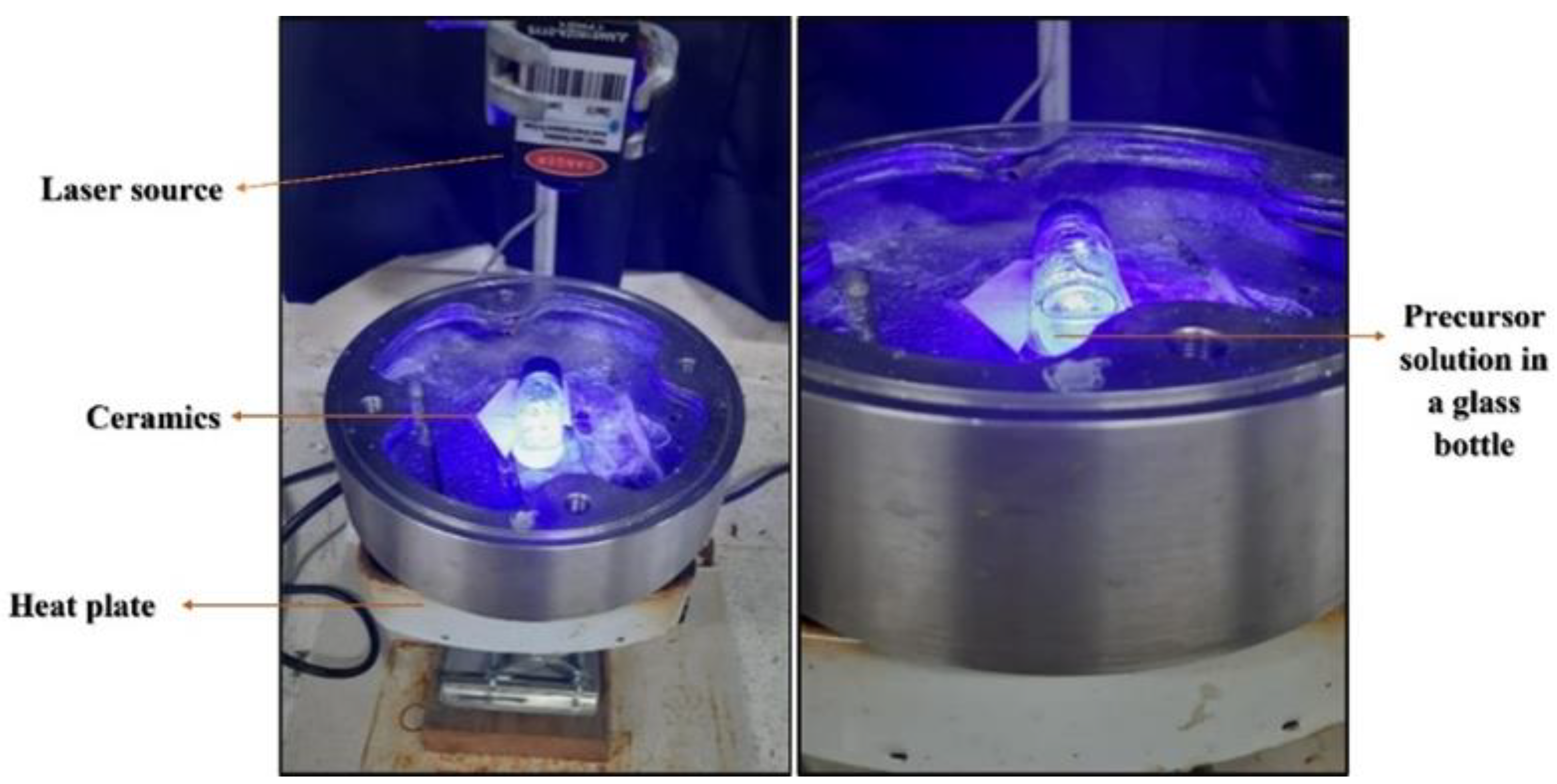
Figure 1. Digital photograph of the set up used in this work. The bottle was put horizontally on the heater with some ceramic pieces below it to prevent the glass bottle from moving.
Photonics 10 00910 g001
Figure 2. Microscopic images of ZnO growth areas and FESEM micrographs of ZnO microrods in the slits that formed during LA-CBD at solution temperatures of 51.11 °C (a) 61.10 °C (b) 69.10 °C (c).
Photonics 10 00910 g002
Figure 3. FESEM images of fabricated ZnO microrods during LACBD at solution temperature of 51.11 °C (a) 61.10 °C (b) 69.10 °C (c).
Photonics 10 00910 g003
Figure 4. Gaussian-fitted histogram plots of ZnO micro-NRs size distribution at solution temperature 51.11 °C (a) 61.10 °C (b) 69.10 °C (c).
Photonics 10 00910 g004
Figure 5. XRD patterns of fabricated ZnO with different solution temperatures of (51.11, 61.10 and 69.10) °C for 30 min by LA-CBD technique under CW laser with power density of 0.16 W/cm2 and peak wavelength of 441.3 nm.
Photonics 10 00910 g005
Figure 6. Absorbance spectra with respective Tauc plot of ZnO microrods formed at 51.11 °C (a,d), 61.10 °C (b,e) and 69.10 °C (c,f).
Photonics 10 00910 g006
Figure 7. (a) Schematic diagram of standard operating procedures of I-V measurement using Keithley 2400 Series SourceMeters (b) Structure of (Ni-ZnO-Ni)/glass PD fabricated in this work.
Photonics 10 00910 g007
Figure 8. I-V characteristics of ZnO microrods which formed at 51.11 °C (a) 61.10 °C (b) and 69.10 °C (c) under dark and illumination of UV lights.
Photonics 10 00910 g008
Figure 9. Photo-response characteristics of the PD based on ZnO formed in LACBD at 51.11 °C (a) 61.10 °C (b) 69.10 °C (c) under UV-A illumination.
Photonics 10 00910 g009
Figure 10. A single normalized cycle of photocurrent response of ZnO formed at 51.11 °C (a) 61.10 °C (b) 69.10 °C (c) to UV-A light exposure under a bias voltage 5 V.
Photonics 10 00910 g010
Table 1. Area of ZnO spots and width of slits on the samples for different solution temperatures.
Average Temperature T   ( ° C ) 51.1161.1069.10
Area of ZnO spot A s p o t ( m m 2 ) 3.0721.1756.657
Mean length of slit L ¯ s l i t ( m m ) 0.2690.2650.131
Table 2. Summary of the number of measurements that were used to construct the histogram, as well as the standard deviation used to determine the average sizes at selected temperatures.
Temperature (°C)Number of MeasurementsStandard Deviation
51.11510.8793
61.101910.8564
69.102380.2926
Table 3. Elemental composition of ZnO microrods at different solution temperatures.
Solution TemperatureAtomic % of ElementZn/O Ratio
ZnO
51.1151.4248.581.0585
61.1052.7447.261.1160
69.1051.8148.191.0751
Table 4. Lattice parameters and structure properties of ZnO-MRs of diffraction peak (002) planes for different temperatures.
Average Temperature T   ( ° C ) 51.1161.1069.10
Diffraction angle2 θ ( ° )34.38534.39534.399
FWHM β   ( r a d , 10 3 ) 1.23811.05542.6747
Interplanar spacing d   ( ) 2.60842.60762.6074
Mean crystalline size D   ( ) 1173.30431376.4933543.1481
Lattice constant a   ( ) 3.01193.01093.0107
c   ( ) 5.21685.21535.2147
Strain value ε a   ( % ) −7.4361−7.4633−7.4738
ε c   ( % ) 0.13490.10540.0941
Dislocation density δ   10 14 l i n e s m 2 0.72640.52783.3897
Table 5. Comparison of the significant parameters of UV PDs based on ZnO between current work and literature.
ZnOMethodSolution
Temperature
( ° C )
Irradiation 
λ ( n m )
Bias
Voltage   ( V )
τ r
( s )
τ d
( s )
R
m A W
S
( % )
Source
NRLACBD51.11380.251.3791.38870.3778.556This work
MircorodLACBD61.10380.251.2601.398131.4439.575This work
MicrorodLACBD69.10380.253.1433.0624.608111.797This work
NRHydrothermal90380555.5033.10102-[34]
NRCBD with air bubbles9538050.9680.5042285.13172.811[20]
NW/NRCVD450365341.3030.70-465.2[35]
NPSpin coating-37552044863750-[36]
NTPLD650365−20.4400.59921500-[37]
Disclaimer/Publisher’s Note: The statements, opinions and data contained in all publications are solely those of the individual author(s) and contributor(s) and not of MDPI and/or the editor(s). MDPI and/or the editor(s) disclaim responsibility for any injury to people or property resulting from any ideas, methods, instructions or products referred to in the content.