Abstract
In off-axis quantitative phase imaging, existing methods of suppressing the zero-frequency component (ZFC) always cause the loss of high-frequency phase information, thus degrading the accuracy of phase reconstruction. To overcome these problems, this paper proposes to preserve the high-frequency information by filtering the intrinsic mode function. In this method, empirical mode decomposition is employed to decompose the interferometric image into a series of intrinsic mode function (IMF) components from high to low frequencies. The decomposed low-frequency IMF components are processed by Gaussian high-pass filters for ZFC suppression, and the high-frequency IMF components and the filtered low-frequency IMF components are combined to obtain the reconstructed hologram. Hilbert transform is then performed on the reconstructed hologram to filter out the conjugate image, leaving only the original image. In order to verify the performance of our proposed method, the phase maps processed by our proposed method are compared with those processed by the Fourier filtering method, wavelet transform-based method and Laplace operator method. The experimental results show that the proposed method not only suppresses ZFC but also achieves higher accuracy in phase reconstruction.
1. Introduction
Quantitative phase imaging (QPI) [1,2,3,4], which is developed based on the principle of light interference and diffraction to reproduce the three-dimensional information of transparent or translucent measured objects [5], has been widely used in industrial micro-machining measurement [6], microscopic measurement [7] and environmental inspection [8]. It can be combined with compressed sensing [9,10,11], deep learning [12,13,14], autofocus [15,16,17], topological modulation [18,19,20] or compensation technology [21,22,23] to achieve higher precision measurement results for various applications.
In general, QPI can be implemented using the principle of digital holography. In off-axis quantitative phase imaging, the ZFC always has a wide distribution range and high energy. Its existence reduces the signal-to-noise ratio of the hologram and, thus, significantly decreases the accuracy of the reproduced image. Therefore, it is necessary to suppress the ZFC in the off-axis QPI.
In order to suppress the ZFC, Cuche et al. [24] proposed that the zero-order image and virtual image can be digitally eliminated by means of filtering their associated spatial frequencies in the computed Fourier transform of the hologram, but spatial filtering using an asymmetric mask to eliminate double images may introduce image distortion or blurring. Pasko et al. [25] proposed a method to suppress the ZFC by subtracting the mean intensity of the hologram. This method need not capture multiple images, but it is only applicable to the case that the reference light distributes uniformly. Guo et al. [26] proposed a method with three images to suppress the ZFC. The three images are a hologram, an image with only the reference light and an image with only the object light. The hologram is used to subtract the intensity of the reference light from the intensity of the object light. However, it is difficult to capture these three images in the same environment [27]. Chen et al. [28] proposed a numerical method based on a linear approximation of the interference equation; this technique, however, is only applicable to amplitude objects with an inline configuration and a plane wave reference whose phase is precisely controlled. Zeng et al. [29] decomposed the captured hologram with the Haar wavelet transform method to suppress the ZFC. The ZFC is considered contained in some low-frequency components of the wavelet transform. However, it is difficult to decide the exact decomposition layers that contain the ZFC, so it is necessary to manually adjust the decomposition layer to find the optimal phase map. Cho et al. [30] used the Laplace operator to suppress the ZFC. Although the method requires only one hologram, the ZFC suppression is not effective because the hologram has a wide spectrum, and it is difficult to extract the original image processed by the Laplace operator. Pavillon et al. [31] proposed a method to suppress the zero-order term in a hologram, based on an iterative principle. However, it requires a priori information about samples or certain imaging conditions. Khare et al. [32] proposed to obtain complex object fields from a single hologram by solving a constrained optimization problem. High-quality image recovery is possible, even when the direct-current (DC) component and cross terms in the hologram overlap in the Fourier domain, but the method requires a priori information or additional constraints to improve the accuracy and stability of the recovery. Baek et al. [33] used the Kramers–Kronig (KK) relation to achieve zero-order term suppression under off-axis geometric spectral coincidence based on the nonlinear filtering method. This method requires only one hologram, but this method is not applicable when the intensity of the reference beam is smaller than that of the object beam, since the power series of the object-reference ratio is divergent in the Fourier domain. Shen et al. [34] proposed a high-throughput artifact-free micro off-axis holographic reconstruction method based on Fourier transform microscopy (FPM). Inspired by the FPM nonlinear optimized phase reconstruction algorithm, constrained updates are performed in an iterative manner between the real and Fourier domains to reconstruct the complex amplitudes by the hologram intensity. However, the iterative process of this algorithm may take a long time, and the algorithm is sensitive to noise, leading to artifacts or image distortion in the reconstruction results.
To overcome these problems, this paper proposes a method to suppress the ZFC of QPI with only one hologram. The hologram captured by the experiment setup is first decomposed by empirical mode decomposition [35] (EMD) into a series of intrinsic mode function (IMF) components from high to low frequencies. Since directly discarding the low-frequency IMF components will lose the detail information present in the low-frequency IMF components, the low-frequency IMF component is processed with a Gaussian high-pass filter [36] to suppress the ZFC and preserve the high-frequency information. The filtered low-frequency IMF components are summed with the high-frequency IMF components to reconstruct a hologram with ZFC cancellation. Then, the Hilbert transform (HT) processing and filtering are performed by applying a function orthogonal to the original signal spectrum to obtain a filtered hologram. By this processing, the conjugate image is suppressed, while the frequency components of the original image are preserved. Therefore, we can suppress the ZFC and preserve the maximum amount of high-frequency information. A higher accurate phase map is obtained to meet the requirements of high-precision reconstruction of phase information.
2. Method of this Paper
Holographic [37] QPI is formed by the interference between object light and reference light. Its spatial expression is
where represents the object light and represents the reference light. constitutes the original image, constitutes the conjugate image and the sum of and constitutes the ZFC. The original image and conjugate image appear as high-frequency components in the frequency spectrum, which is the item with a relatively fast frequency change. The ZFC is the term for frequency transformation, referring to the low-frequency part of the frequency spectrum. In actual numerical reconstruction, the phase information that should be recovered is in or , but the sum of and occupies a larger range than or in the frequency spectrum. Thus, suppressing the ZFC is equivalent to suppressing the sum of and .
In order to suppress the sum of and (ZFC), first, we use two-dimensional EMD to decompose the captured hologram to obtain a series of IMF components from high to low frequencies. Then, we apply Gaussian high-pass filtering to the low-frequency IMF components containing the ZFC and reconstruct the original signal together with the high-frequency IMF components that do not contain the ZFC. The Hilbert transform (HT) [38,39,40,41] is carried out on the reconstructed hologram to filter out the conjugate image and leave the original image. After that, we can obtain a higher accuracy phase map to meet the requirements of high-accuracy reconstruction of the object spatial information.
The decomposition process of EMD is described as follows:
- Suppose that is the hologram image to be analyzed. Firstly, find the maxima and minima of f(x, y) and construct the maximum surface and the minimum surface by interpolation. The effect of this step is to capture the dominant oscillatory patterns present in the hologram. The mean value of the upper and lower envelope surfaces is
The difference between the and is recorded as , and then there is
- Take as the new input and repeat the above process times. Until Equation (4) is satisfied, the cycle can stop, where SD is generally between 0.1 and 0.5. is generally 0.2.
It is worth noting that the SD is essentially the standard deviation between the results of the two iterations of the calculation. It shows the degree of dispersion between the results of two calculations. When is satisfied, the improvement in the computational accuracy is not significant if the cycle is performed again. At this time, is an IMF, which contains the image component of the highest frequency of the image, denoted as . The effect of this step is to extract the most significant oscillatory mode from the hologram, capturing a specific frequency component.
- is denoted as the remaining image with the high-frequency part removed. The effect of this step is to remove the contribution of the extracted IMF from the hologram, focusing on the residual information.
- Repeat the above process with as the new image to be analyzed, and then the second IMF can be obtained. The effect of this step is to capture additional oscillatory modes of decreasing frequency from the hologram, revealing progressively lower-frequency components.
- After times of the above process, when and are less than the predetermined error or is a monotone function, the IMF cannot be extracted from the original . The original image can be shown in Equation (6). The effect of this step is to provide a representation of the hologram as a combination of different frequency components.
Then, we Gaussian high-pass filter the low-frequency IMF components; C1 and C2 represent the high-frequency components of the hologram, and the other IMF components represent the low-frequency components.
The two-dimensional Fourier transform of yields its frequency domain information.
where is the two-dimensional Fourier transform of , and is the frequency domain coordinate.
The Gaussian high-pass filter can be expressed by the following equation:
where is the distance from the frequency domain point to the image centroid and is the cutoff frequency. The cutoff frequency determines the intensity and edge sharpness of the filter.
By multiplying the frequency domain image by the coefficients of the high-pass filter, the processed frequency domain image is obtained as follows:
Finally, the processed frequency domain image is inversely transformed to obtain the filtered time domain image:
where is the filtered time domain image.
At this point, the reconstructed hologram is expressed as
After we obtain the new hologram, we perform the Hilbert transform on the reconstructed hologram to filter out the conjugate image and leave the original image. This makes subsequent numerical reconstruction more convenient. HT is a method commonly used in signal analysis and processing. For one-dimensional signals, it is essentially a convolution operation between the signal and , i.e., denotes the time coordinate of the signal, which varies in the range of the true signal.
where represents the HT operator, and the Fourier transform (FT) of Equation (8) can be obtained.
where is the FT operator, is the spectrum and is the sign function.
At this time, the one-dimensional HT is equivalent to a phase shifter. After the HT, the positive frequency component of the signal in the frequency domain has a phase shift, and the negative frequency component has a phase shift. The HT only changes the phase value of the signal.
Assuming is an arbitrary two-dimensional signal after the two-dimensional HT is converted into . and represent the time variables of the two-dimensional signal, indicating the position or coordinates of the signal in different dimensions. Its frequency domain response distribution is divided into four regions. A regional value is 1. Another with the first region into a center of symmetry area value is −1. And the remaining two area amplitude is zero. Thus, the two-dimensional HT is equivalent to a “cross” filter.
where represents the instantaneous amplitude of a two-dimensional signal and represents the instantaneous phase of the two-dimensional signal.
After that, the phase information is recovered from the numerical reconstruction. As it is a package state, an unwrapping operation is required. Aiming at the error source of the phase information, the corresponding phase correction method is used to correct the unwrapping phase information. The operation flow chart of the method in this paper is shown in Figure 1.
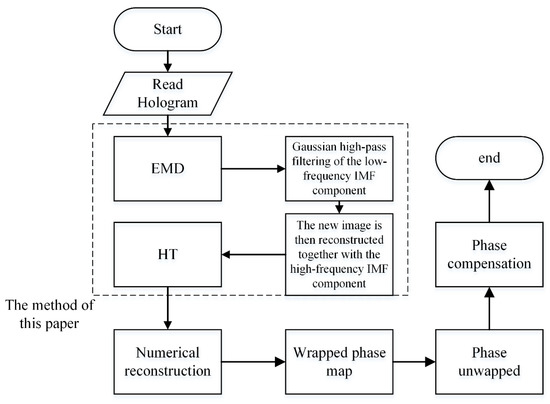
Figure 1.
The method flow chart of this paper.
3. Experiment and Results Analysis
In this paper, we establish a Mach–Zehnder recording optical system for quantitative phase imaging. It is shown in Figure 2. The light source is a He–Ne laser with a wavelength of 632.8 nm. After the light passes through the beam expander collimator BE, it is split into two beams of equal intensity by the beam splitter BS1. One beam passes through the sample and is reflected by the mirror M1 to the beam splitter BS2. This beam of light is recorded as the object light. Another beam is directly reflected by the mirror M2 to BS2 and is recorded as the reference light. Finally, the object light and the reference light are interfered at the beam splitter BS2, and the hologram patterns are recorded with CCD (pixel size , , resolution 1920 × 1200).
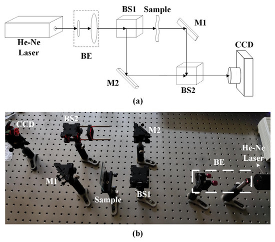
Figure 2.
Recording optical system. (a) Mach–Zehnder recording optical system schematic. (b) Mach–Zehnder recording optical system physical diagram.
3.1. ZFC Suppression in QPI
In our experiments, we used the sample shown in Figure 3a,c and the leaf blade shown in Figure 3b as samples. Their corresponding holograms captured by the experimental setup are shown in Figure 3d–g, respectively.
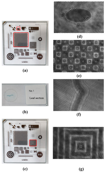
Figure 3.
Samples and holograms. (a,c) The sample plate. (b) The leaf section. (d,e) The hologram of (a). (f) The hologram of (b). (g) The hologram of (c).
We implemented two-dimensional power spectral analysis on the captured holograms to observe the spectral distribution for further processing. Figure 4a–d show the power spectrum of the corresponding holograms. The ZFC is located in the center of the spectrum, occupying a larger area than the original image and conjugate image and partially overlapping with the original image and conjugate image, so it is difficult to filter the ZFC using traditional Fourier filtering. Subsequently, the captured hologram is subjected to 2D EMD to obtain a series of IMF components from high to low, of which the low-frequency IMF components are filtered using a Gaussian high-pass filter, and then the original signal is reconstructed together with the high-frequency IMF components. According to the above analysis, Equation (12) is used to reconstruct a new hologram with ZFC suppression. After that, we perform the HT to filter out the conjugate image and leave the original image. The corresponding spectrum diagrams are shown in Figure 4e–h, respectively. As can be seen, the zero-frequency component and conjugate image have been suppressed, and the original image is still intact and without any loss.
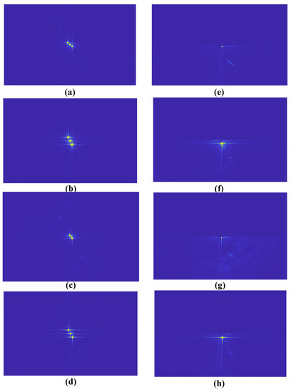
Figure 4.
The frequency spectrum diagrams. (a) The frequency spectrum diagram of Figure 3d. (b) The frequency spectrum diagram of Figure 3e. (c) The frequency spectrum diagram of Figure 3f. (d) The frequency spectrum diagram of Figure 3g. (e) The frequency spectrum diagram of Figure 3d processed by the proposed method. (f) The frequency spectrum diagram of Figure 3e processed by the proposed method. (g) The frequency spectrum diagram of Figure 3f processed by the proposed method. (h) The frequency spectrum diagram of Figure 3g processed by the proposed method.
Then, the holograms undergo numerical reconstruction. The angular spectrum diffraction method [42,43,44] is used to simulate the diffraction process of light to obtain the reconstructed image of the hologram. From the reconstructed image, phase information can be recovered. Since the phase information is wrapped within, the phase unwrapping operation is required. The least squares method based on the discrete cosine transform (DCT) [45] is adopted for phase unwrapping. For off-axis quantitative phase imaging, the tilt angle between the object light and the reference light is the main source of phase error. The least squares fitting method [46] is used to correct the unwrapping phase information, and the results of the phase correction are shown in Figure 5. From these figures, we can see that the reconstructed phase image processed by the proposed method is more regular and has richer and more prominent phase details than the reconstructed phase map processed by the traditional Fourier filtering method. The left side of the elliptical area in Figure 5a is relatively high, while the right side is relatively low, and the small raised pattern in Figure 5b is obviously missing. Figure 5c is closer to Figure 5g, and the bars in Figure 5d are jaggedly loaded compared to Figure 5h. Therefore, according to the imaging results, the phase distribution recovered by the proposed method is more accurate, and it has certain advantages in quantitative phase imaging.
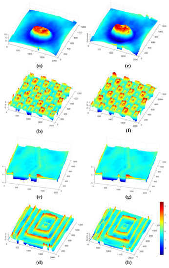
Figure 5.
Phase maps. (a) The reconstructed phase map of Figure 3d. (b) The reconstructed phase map of Figure 3e. (c) The reconstructed phase map of Figure 3f. (d) The reconstructed phase map of Figure 3g. (e) The reconstructed phase map of Figure 3d processed by the proposed method. (f) The reconstructed phase map of Figure 3e processed by the proposed method. (g) The reconstructed phase map of Figure 3f processed by the proposed method. (h) The reconstructed phase map of Figure 3g processed by the proposed method.
3.2. ZFC Suppression Comparison Experiment in QPI
In order to verify the performance of our proposed method, we compare it with the Haar wavelet transform method [29] and the Laplace operator-based method [30], and the holograms reconstructed by the two methods are processed with the HT to filter out the conjugate images separately. The frequency spectrum diagrams of the holograms processed by the Haar wavelet transform are shown in Figure 6a–d, respectively. The frequency spectrum diagrams of the holograms processed by the Laplace operation are shown in Figure 6e–h, respectively. From the spectrograms of the holograms processed by these two methods, it can be seen that the zero-level and conjugate images have been suppressed, but the original images both produce a loss in detail.
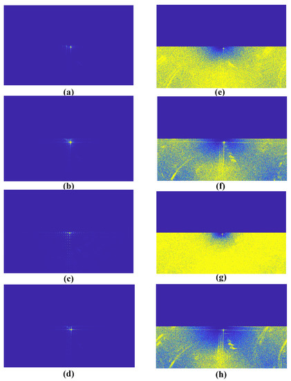
Figure 6.
The frequency spectrum diagrams. (a) The frequency spectrum diagram of Figure 3d processed by the Haar wavelet transform. (b) The frequency spectrum diagram of Figure 3e processed by the Haar wavelet transform. (c) The frequency spectrum diagram of Figure 3f processed by the Haar wavelet transform. (d) The frequency spectrum diagram of Figure 3g processed by the Haar wavelet transform. (e) The frequency spectrum diagram of Figure 3d processed by the Laplace operator. (f) The frequency spectrum diagram of Figure 3e processed by the Laplace operator. (g) The frequency spectrum diagram of Figure 3f processed by the Laplace operator. (h) The frequency spectrum diagram of Figure 3g processed by the Laplace operator.
After numerical reconstruction, phase unwrapping, and phase correction of the holograms processed by the Haar wavelet transform, the final phase maps are shown in Figure 7a–d, respectively. By Laplace operator processing, the final phase maps are shown in Figure 7e–h, respectively. It can be seen that the reconstructed phase images processed by both methods suffer from significant phase deformation and high-frequency component loss. The elliptical projections in Figure 7a,e are both clearly missing, the lower left corner of the small raised pattern in Figure 7b,f is also missing, the specific outline in the middle part of Figure 7c,g can no longer be seen and the outlines of Figure 7d,h appear jagged.
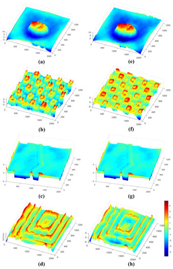
Figure 7.
The phase maps. (a) The reconstructed phase map of Figure 3d processed by the Haar wavelet transform. (b) The reconstructed phase map of Figure 3e processed by the Haar wavelet transform. (c) The reconstructed phase map of Figure 3f processed by the Haar wavelet transform. (d) The reconstructed phase map of Figure 3g processed by the Haar wavelet transform. (e) The reconstructed phase map of Figure 3d processed by the Laplace operator. (f) The reconstructed phase map of Figure 3e processed by the Laplace operator. (g) The reconstructed phase map of Figure 3f processed by the Laplace operator. (h) The reconstructed phase map of Figure 3g processed by the Laplace operator.
According to Figure 4 and Figure 6, our proposed method can not only suppress the ZFC of the hologram but also filter out the conjugate image. It will be more convenient for the subsequent numerical reconstruction of the wrapped phase map. Although the Laplace operator method can suppress the ZFC, its frequency spectrum diagram is not as good as our proposed method or the Haar wavelet transform method. On the other hand, the Haar wavelet transform method should manually adjust the number of decomposition layers to search for the optimal result of ZFC suppression, while our proposed method avoids this manual adjustment to suppress the ZFC.
In order to perform quantitative analysis on the reconstructed phase map after noise reduction, the peak signal-to-noise ratio (PSNR) and structural similarity (SSIM) are used as the indexes for quantitative analysis in this paper. The original reference phase is obtained using a method of eliminating zero-frequency components based on image subtraction, which can effectively remove zero-frequency components in the case of serious overlap between zero-frequency components and +1 level images, by recording a hologram, an image with only reference light and an image with only object light.
The calculation formula of the PSNR is as follows:
where MSE is the mean square error between the original reference image and the processed image , and and are the width and length of the image, respectively.
The formula of the SSIM is as follows:
where denotes the brightness of the image and denotes the contrast of the image. The larger the value of the , the smaller the distortion of the image. The value of is equal to 1 when two images are at the same time.
The calculated results of the and corresponding to the reconstructed phase maps of Figure 3d–g after processing by the method proposed in this paper, the traditional Fourier filtering method, the Haar wavelet transform method and the Laplace operator method are shown in Table 1, Table 2, Table 3 and Table 4.

Table 1.
PSNR and SSI calculation results of reconstructed phase after processing Figure 3d with different ZFC suppression methods.

Table 2.
PSNR and SSI calculation results of reconstructed phase after processing Figure 3e with different ZFC suppression methods.

Table 3.
PSNR and SSI calculation results of reconstructed phase after processing Figure 3f with different ZFC suppression methods.

Table 4.
PSNR and SSI calculation results of reconstructed phase after processing Figure 3g with different ZFC suppression methods.
It can be seen from the quantitative analysis and calculation results in Table 1, Table 2, Table 3 and Table 4 that the PSNR and SSIM calculation of our proposed method is higher than the traditional Fourier filter method, the Haar wavelet transform method and the Laplace operator.
In order to verify the accuracy of quantitative phase reconstruction after suppressing the ZFC, the cross-sectional curve comparison analysis is performed at x = 717 of the phase diagram shown in Figure 5a,e and Figure 7a,e, while comparing it with the original reference phase diagram, and the results are shown in Figure 8a; the cross-sectional curve comparison analysis is performed at y = 373 of the phase diagram shown in Figure 5b,f and Figure 7b,f, and the results are shown in Figure 8b; the cross-sectional curve comparison analysis is compared with the original reference phase diagram, and the results are shown in Figure 8b; the cross-sectional curve comparison analysis is performed at x = 717 of the phase diagram shown in Figure 5c,g and Figure 7c,g while comparing it with the original reference phase diagram, and the results are shown in Figure 8c; in Figure 5d,h and Figure 7d,h, the comparative analysis of the cross-sectional curves was performed at y = 373 of the phase diagram shown and also compared with the original reference phase diagram, and the results are shown in Figure 8d.
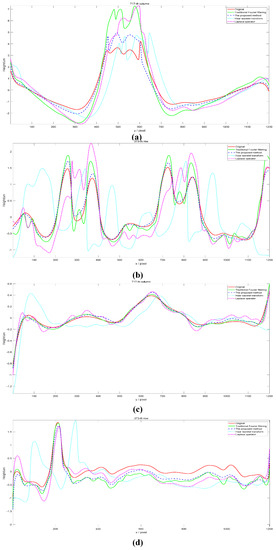
Figure 8.
Phase section analysis. (a) The cross-section curve at x = 717 of the phase maps shown in Figure 5a,e and Figure 7a,e and the original phase map. (b) The cross-section curve at y = 373 of the phase maps shown in Figure 5b,f and Figure 7b,f and the original phase map. (c) The cross-section curve at x = 717 of the phase maps shown in Figure 5c,g and Figure 7c,g and the original phase map. (d) The cross-section curve at y = 373 of the phase maps shown in Figure 5d,h and Figure 7d,h and the original phase map.
In Figure 8, the red solid line represents the curve of the original reference phase diagram. The green solid line represents the curve of the phase diagram corresponding to the conventional Fourier filtering method. The blue dashed line represents the curve of the phase diagram corresponding to our proposed method. The cyan dots represent the curves of the phase diagram corresponding to the Haar transform method. The purple dashed line represents the curve of the phase diagram corresponding to the Laplace operator.
It can be seen from Figure 8a–d that the trend of the green dashed line, the blue point line and the yellow point line are basically the same as the trend of the red solid line. However, the experimental results show that the deviation of the blue dashed line from the red solid line at the peak is significantly smaller than the deviation of the green dashed line from the red solid line at the peak, the deviation of the cyan dotted line from the red solid line at the peak and the deviation of the purple dashed line from the red solid line at the peak. In particular, in Figure 8a, the deviation rate of the peak between the green solid line and the red solid line is 72.49%. The peak deviation rate between the blue dotted line and the red solid line is 13.3%. The peak deviation rate between the cyan dotted line and the red solid line is 17.27%. The peak deviation rate between the purple dotted line and the red solid line is 73.32%.
In order to compare the accuracy of the phase diagram cross-sectional curves processed by the methods mentioned in this paper, the standard deviation [47] is used to measure the phase diagram cross-sectional curves corresponding to the conventional Fourier filtering method, the phase diagram cross-sectional curves corresponding to the method proposed in this paper, the phase diagram cross-sectional curves corresponding to the Haar wavelet transform method and the phase diagram cross-sectional curves corresponding to the Laplace operator. The standard deviation is defined as the average distance between the experimental data and the reference data. The standard deviation can reflect the degree of dispersion of a dataset. The smaller the standard deviation, the smaller the deviation of the experimentally obtained data from the reference data and the higher the accuracy. The standard deviation can be expressed as
where represent the recovered phase diagram cross-sectional curve data and the real reference phase diagram cross-sectional curve data, respectively. The standard deviation values are shown in Table 5.

Table 5.
Calculated standard deviations of cross-sectional curves in Figure 8a–d.
It can be seen from the standard deviation calculation results in Table 5 that the standard deviation calculation results of the cross-sectional curves corresponding to the proposed method are smaller than those of the traditional Fourier filter, the Haar wavelet transform and the Laplace operator.
According to these results, we can conclude that the error of our proposed method is the smallest compared to these algorithms.
4. Conclusions
In this paper, we propose a Gaussian high-pass filtering method based on the Hilbert–Huang transform to suppress the zero-frequency component (ZFC) of Quantitative phase imaging (QPI) with only one shot. Through the Mach–Zehnder interferometer recording optical system, the captured hologram is first decomposed by empirical mode decomposition (EMD) to a series of intrinsic mode function (IMF) components from high to low-frequency components. The low-frequency components represent the ZFC of the hologram, so we process the low-frequency IMF components containing the ZFC with Gaussian high-pass filtering to obtain the ZFC-suppressed data and then reconstruct the original signal together with the high-frequency IMF components that do not contain the ZFC. The Hilbert transform (HT) is then applied to the reproduced hologram, and the Fourier transform is first applied to extract the frequency domain information from the hologram, and then a function orthogonal to the original signal spectrum is applied to filter the hologram to obtain the filtered hologram, thus filtering out the ±1 level image and retaining the +1 level image. Therefore, the new phase map can be recovered from the HHT-processed hologram by the angular spectrum diffraction method, the discrete cosine-based least squares method and the least squares fitting method. In our research, the reconstructed phase diagrams after ZFC elimination by the method proposed in this paper, the conventional Fourier filtering method, the Haar wavelet transform method and the Laplace operator method are quantitatively analyzed using the peak signal-to-noise ratio (PSNR) and structural similarity (SSIM), and the calculated results are better than the other three ZFC suppression methods. By analyzing the cross-sectional curves of the reconstructed phase diagram after ZFC suppression by different methods, it is found that the deviation of the proposed method from the original phase is smaller. The experimental results show that our proposed method outperforms the other three ZFC suppression methods in terms of performance, with a better ZFC suppression effect and higher phase reconstruction accuracy.
Author Contributions
Conceptualization, J.L., C.M. and Y.D.; methodology, C.M. and Y.D.; software, C.M.; validation, C.M.; formal analysis, C.M., Y.D. and J.X.; investigation, C.M.; resources, J.L., Y.D. and J.X.; data curation, C.M.; writing—original draft preparation, C.M.; writing—review and editing, C.M. and Y.D.; visualization, C.M. and Y.D.; supervision, Y.D.; project administration, J.L., Y.D.; funding acquisition, J.L., Y.D. and J.X. All authors have read and agreed to the published version of the manuscript.
Funding
This work was supported by the key scientific research platforms and projects of ordinary universities in Guangdong Province (2021KCXTD051) and the Wuyi University Hong Kong and Macau Joint R&D Fund Project (Grant No. 2021WGALH17).
Institutional Review Board Statement
Not applicable.
Informed Consent Statement
Not applicable.
Data Availability Statement
No data were generated or analyzed in the presented research.
Conflicts of Interest
The authors declare no conflict of interest.
References
- Popescu, G. Quantitative Phase Imaging of Cells and Tissues; McGraw-Hill Education: New York, NY, USA, 2011. [Google Scholar]
- Trusiak, M.; Mico, V.; Garcia, J.; Patorski, K. Quantitative phase imaging by single-shot Hilbert–Huang phase microscopy. Opt. Lett. 2016, 41, 4344–4347. [Google Scholar] [CrossRef] [PubMed]
- Sitthisang, S.; Boonruangkan, J.; Leong, M.F.; Chian, K.S.; Kim, Y.J. Quantitative Phase Imaging to Study the Effect of Sodium Dodecyl Surfactant on Adherent L929 Fibroblasts on Tissue Culture Plates. Photonics 2021, 8, 508. [Google Scholar] [CrossRef]
- Eldridge, W.J.; Sheinfeld, A.; Rinehart, M.T.; Wax, A. Imaging deformation of adherent cells due to shear stress using quantitative phase imaging. Opt. Lett. 2016, 41, 352–355. [Google Scholar] [CrossRef] [PubMed]
- Ding, Y.; Peng, K.; Yu, M.; Lu, L.; Zhao, K. Fringe order correction for the absolute phase recovered by two selected spatial frequency fringe projections in fringe projection profilometry. Rev. Sci. Instrum. 2017, 88, 083104. [Google Scholar] [CrossRef] [PubMed]
- Brito, I.V.; Gesualdi, M.R.R.; Muramatsu, M.; Ricardo, J. Phase-shifting Real-time Holographic Microscopy applied in micro-structures surface analysis. J. Phys. Conf. Ser. 2011, 274, 012072. [Google Scholar] [CrossRef]
- Zhang, M.L.; Ma, Y.; Wang, Y.; Wen, K.; Zheng, J.; Liu, L.; Gao, P. Polarization grating based on diffraction phase microscopy for quantitative phase imaging of paramecia. Opt. Express 2020, 28, 29775–79787. [Google Scholar] [CrossRef]
- Zhang, M.; Liu, J.; Dou, J.; Zhang, J.; Zhang, L.; Di, J.; Zhao, J. Simultaneous measurement of near-water-film air temperature and humidity fields based on dual-wavelength digital holographic interferometry. Opt. Express 2022, 30, 17278–17289. [Google Scholar] [CrossRef]
- Luo, Z.P.; Ma, J.S.; Su, P.; Cao, L.C. Digital holographic phase imaging based on phase iteratively enhanced compressive sensing. Opt. Lett. 2019, 44, 1395–1398. [Google Scholar] [CrossRef]
- Zhang, X.; Meng, X.; Yin, Y.; Yang, X.; Wang, Y.; Li, X.; Peng, X.; He, W.; Dong, G.; Chen, H. Two-level image authentication by two-step phase-shifting interferometry and compressive sensing. Opt. Lasers Eng. 2018, 100, 118–123. [Google Scholar] [CrossRef]
- Reddy, B.L.; Ramachandran, P.; Nelleri, A. Compressive complex wave retrieval from a single off-axis digital Fresnel hologram for quantitative phase imaging and microlens characterization. Opt. Commun. 2021, 478, 126371. [Google Scholar]
- Di, J.L.; Wu, J.; Wang, K.Q.; Tang, J.; Li, Y.; Zhao, J.L. Quantitative phase imaging using deep learning-based holographic microscope. Front. Phys. 2021, 9, 651313. [Google Scholar] [CrossRef]
- Chen, N.; Wang, C.; Heidrich, W. Holographic 3D particle imaging with model-based deep network. IEEE Trans. Comput. Imaging 2021, 7, 288–296. [Google Scholar] [CrossRef]
- Rivenson, Y.; Liu, T.R.; Wei, Z.S.; Zhang, Y.B.; Haan, K.D.; Ozcan, A. PhaseStain: The digital staining of label-free quantitative phase microscopy images using deep learning. Light Sci. Appl. 2019, 8, 23. [Google Scholar] [CrossRef]
- Zhang, Y.; Huang, Z.; Jin, S.; Cao, L. Autofocusing of in-line holography based on compressive sensing. Opt. Lasers Eng. 2021, 146, 106678. [Google Scholar] [CrossRef]
- Ren, Z.B.; Lam, E.Y.; Zhao, J.L. Acceleration of autofocusing with improved edge extraction using structure tensor and Schatten norm. Opt. Express 2020, 28, 14712–14728. [Google Scholar] [CrossRef] [PubMed]
- Guo, C.F.; Bian, Z.C.; Alhudaithy, S.; Jiang, S.W.; Tomizawa, Y.; Song, P.M.; Wang, T.B.; Shao, X.P. Brightfield, fluorescence, and phase-contrast whole slide imaging via dual-LED autofocusing. Biomed. Opt. Express 2021, 12, 4651–4660. [Google Scholar] [CrossRef]
- Li, R.; Cao, L. Complex wavefront sensing based on coherent diffraction imaging using vortex modulation. Sci. Rep. 2021, 11, 9019. [Google Scholar] [CrossRef]
- Ionel, L.; Ursescu, D.; Neagu, L.; Zamfirescu, M. On-site holographic interference method for fast surface topology measurements and reconstruction. Phys. Scr. 2015, 90, 065502. [Google Scholar] [CrossRef]
- Liu, X.; Long, J.; Ding, Y.; Hu, Y.; Du, Z.; Xu, B.; Deng, D. Measuring the refractive index of scintillation crystal with a Mach-Zehnder interferometer. Opt. Contin. 2022, 1, 909–918. [Google Scholar] [CrossRef]
- Deng, D.; Qu, W.; He, W.; Liu, X.; Peng, X. Phase aberration compensation for digital holographic microscopy based on geometrical transformations. J. Opt. 2019, 21, 085702. [Google Scholar] [CrossRef]
- Singh, M.; Khare, K. Accurate efficient carrier estimation for single-shot digital holographic imaging. Opt. Lett. 2016, 41, 4871–4874. [Google Scholar] [CrossRef]
- Liu, Y.; Wang, Z.; Li, J.S.; Gao, J.M.; Huang, J.H. Total aberrations compensation for misalignment of telecentric arrangement in digital holographic microscopy. Opt. Eng. 2014, 53, 112307. [Google Scholar] [CrossRef]
- Cuche, E.; Marquet, P.; Depeursinge, C. Spatial filtering for zero-order and twin-image elimination in digital off-axis holography. Appl. Opt. 2000, 39, 4070–4075. [Google Scholar] [CrossRef] [PubMed]
- Pasko, S.; Jozwicki, R. Improvement methods of reconstruction process in digital holography. Opto-Electron. Rev. 2003, 11, 203–209. [Google Scholar]
- Guo, C.S.; Wang, W.T.; Li, J.; Gao, T.J. Elimination of zero-order diffraction spot in hologram digital reconstruction (in Chinese). Acta Opt. Sin. 1998, 08, 114–117. [Google Scholar]
- Halaq, H.; Takakura, Y.; Vukicevic, D. Zero order elimination for digital holograms: Study of setup dependent methods. In Proceedings of the 2019 International Conference on Intelligent Systems and Advanced Computing Sciences (ISACS), Taza, Morocco, 26–27 December 2019. [Google Scholar]
- Chen, G.-L.; Lin, C.-Y.; Kuo, M.-K.; Chang, C.-C. Numerical suppression of zero-order image in digital holography. Opt. Express 2007, 15, 8851–8856. [Google Scholar] [CrossRef]
- Zeng, L.; Gu, J.H.; Zhou, H. Application of wavelet transform to eliminate zero-order image of digital holography. J. Soochow Univ. (Nat. Sci. Ed.) 2010, 26, 56–60. [Google Scholar]
- Cho, C.; Choi, B.; Kang, H.; Lee, S. Laplace operation-based DC noise reduction in digital holography. IEEE Photonics Technol. Lett. 2013, 25, 1188–1191. [Google Scholar] [CrossRef]
- Pavillon, N.; Arfire, C.; Bergoënd, I.; Depeursinge, C. Iterative method for zero-order suppression in off-axis digital holography. Opt. Express 2010, 18, 15318–15331. [Google Scholar] [CrossRef]
- Khare, K.; Ali PT, S.; Joseph, J. Single shot high resolution digital holography. Opt. Express 2013, 21, 2581–2591. [Google Scholar] [CrossRef]
- Baek, Y.S.; Lee, K.R.; Shin, S.; Park, Y. Kramers–Kronig holographic imaging for high-space-bandwidth product. Optica 2019, 6, 45–51. [Google Scholar] [CrossRef]
- Shen, Q.; Sun, J.; Fan, Y.; Li, Z.; Gao, P.; Chen, Q.; Zuo, C. High-throughput artifact-free slightly off-axis holographic imaging based on Fourier ptychographic reconstruction. Front. Photonics 2022, 3, 936561. [Google Scholar] [CrossRef]
- Zhan, X.; Gan, C.; Ding, Y.; Hu, Y.; Xu, B.; Deng, D.; Liao, S.; Xi, J. Speckle Noise Suppression Based on Empirical Mode Decomposition and Improved Anisotropic Diffusion Equation. Photonics 2022, 9, 611. [Google Scholar] [CrossRef]
- Dong, J.; Yetisen, A.K.; Dong, X.; Brändle, F.; Jakobi, M.; Liu, Z.; Salazar, F.; Koch, A.W. Low-pass filtering compensation in common-path digital holographic microscopy. Appl. Phys. Lett. 2020, 117, 121105. [Google Scholar] [CrossRef]
- Gabor, D. A new microscopic principle. Nature 1948, 161, 777–778. [Google Scholar] [CrossRef]
- Huang, N.E.; Shen, Z.; Long, S.R.; Wu, M.C.; Shih, H.H.; Zheng, Q.; Yen, N.C.; Chi, C.; Liu, H.H. The empirical mode decomposition and the Hilbert spectrum for nonlinear and non-stationary time series analysis. Proc. Math. Phys. Eng. Sci. 1971, 454, 903–995. [Google Scholar] [CrossRef]
- Nunes, J.C.; Bouaoune, Y.; Delechelle, E.; Niang, O.; Bunel, P. Image analysis by bidimensional empirical mode decomposition. Image Vis. Comput. 2003, 21, 1019–1026. [Google Scholar] [CrossRef]
- Chen, J.; Wang, L.; Wang, P.; Che, A. Failure mechanism investigation on loess–mudstone landslides based on the Hilbert–Huang transform method using a large-scale shaking table test. Eng. Geol. 2022, 302, 106630. [Google Scholar] [CrossRef]
- Svetlakov, M.; Kovalev, I.; Konev, A.; Kostyuchenko, E.; Mitsel, A. Representation Learning for EEG-Based Biometrics Using Hilbert–Huang Transform. Computers 2022, 11, 47. [Google Scholar] [CrossRef]
- Anand, A.; Chhaniwal, V.K.; Javidi, B. Real-Time Digital Holographic Microscopy for Phase Contrast 3D Imaging of Dynamic Phenomena. J. Disp. Technol. 2010, 6, 500–505. [Google Scholar] [CrossRef]
- Wang, F.; Bian, Y.M.; Wang, H.C.; Lyu, M.; Pedrini, G.; Osten, W.; Barbastathis, G.; Situ, G.H. Phase imaging with an untrained neural network. Light Sci. Appl. 2020, 9, 77. [Google Scholar] [CrossRef] [PubMed]
- Huang, Z.Z.; Cao, L.C. Bicubic interpolation and extrapolation iteration method for high resolution digital holographic reconstruction. Opt. Lasers Eng. 2020, 130, 106090. [Google Scholar] [CrossRef]
- Ghiglia, D.C.; Romero, L.A. Robust two-dimensional weighted and unweighted phase unwrapping that uses fast transforms and iterative methods. J. Opt. Soc. Am. A 1994, 11, 107–117. [Google Scholar] [CrossRef]
- Kong, I.B.; Kim, S.W. General algorithm of phase-shifting interferometry by iterative least-squares fitting. Opt. Eng. 1995, 34, 183–188. [Google Scholar] [CrossRef]
- Gao, Y.F.; Guo, H.J.; Song, X.F.; Yu, M.J.; Wang, H.Y. Digital holographic phase reconstruction technology based on Hilbert transform. Opt. Laser Technol. 2015, 39, 266–269. [Google Scholar]
Disclaimer/Publisher’s Note: The statements, opinions and data contained in all publications are solely those of the individual author(s) and contributor(s) and not of MDPI and/or the editor(s). MDPI and/or the editor(s) disclaim responsibility for any injury to people or property resulting from any ideas, methods, instructions or products referred to in the content. |
© 2023 by the authors. Licensee MDPI, Basel, Switzerland. This article is an open access article distributed under the terms and conditions of the Creative Commons Attribution (CC BY) license (https://creativecommons.org/licenses/by/4.0/).