Abstract
Light scattering is a common physical phenomenon in nature. The scattering medium will randomly change the direction of incident light propagation, making it difficult for traditional optical imaging methods to detect objects behind the scattering body. Wiener filtering deconvolution technology based on the optical memory effect has broad application prospects by virtue of its advantages, such as fast calculation speed and low cost. However, this method requires manual parameter adjustment, which is inefficient and cannot deal with the impact of real-scene noise. This paper proposes an improved Wiener filtering deconvolution method that improves the exposure dose during the speckle collection, can quickly obtain the optimal parameter during the calculation phase, and can be completed within 41.5 ms (for a 2448 × 2048 image). In addition, a neural network denoising model was proposed to address the noise issue in the deconvolution recovery results, resulting in an average improvement of 27.3% and 186.7% in PSNR and SSIM of the images, respectively. The work of this paper will play a role in achieving real-time high-quality imaging of scattering media and be helpful in studying the physical mechanisms of scattering imaging.
1. Introduction
As a kind of optical imaging, vision is the most important way to obtain information. However, the scattering media, including diffusors, fog and rain, flowing air, etc., have become one of the essential factors in optical imaging deterioration [1]. Considering its complex internal structure and inhomogeneous properties, the scattering medium changes the transmissive trace of light randomly inside, which makes the patterns of the objects behind the diffusor seriously disturbed and unrecognizable [2]. Thus, in recent years, many approaches have been proposed to solve the problem of scattered imaging restoration, such as wavefront shaping techniques [3,4,5], phase conjugation [6,7,8], transmission matrix measurements [9,10,11], and deep learning [12,13,14]. However, these methods still have some drawbacks, such as slow speed, cumbersome operation, and dependence on the number of samples. Speckle correlation image restoration techniques based on the optical memory effect (OME) have been provided [15,16,17], which are considered one of the most promising solutions because of their non-invasive nature and ease of implementation.
The technique of scattered imaging deconvolution is one of the classical restorations based on OME. It can achieve fast image reconstruction as long as the point spread function (PSF) of the scattering medium is obtained. Zhuang et al. proposed a scattering recovery imaging method using the point diffusion function of the scattering medium for deconvolution and realized color imaging recovery [18]. Li et al. proposed spatial lamination imaging technology through multiple openings on the object surface, which can improve the resolution and stability of the recovered object [19]. However, the effectiveness of this method depends on the number of measurements, which prevents its real-time application. Consequently, time consumption is also a key issue in the scattered image restoration and shows the significance of the quality of reconstruction, especially the contrast, stability, and noise resistance.
In recent years, the time-consuming use of digital phase conjugation technology to achieve refocusing through scattering media has been 0.7 s [8], and the deep learning method achieves 128 × 128 pixel image reconstruction within tens of milliseconds [14], but the Wiener filtering deconvolution method takes less than 1 millisecond at 2048 × 2048 pixels. The only variable parameter, K, has a great influence on the restoration quality. However, to acquire a proper K value for different targets requires many iterations; thus, one of the key issues of this paper is to seek an optimized K value, which is shown to reduce time consumption significantly compared to traditional Wiener filtering.
In order to decrease reconstruction image noise and increase contrast, this paper provides an optimized scattering image restoration method that includes three steps: step1: exposure-match scattered image record; step2: deconvolution with a novel image evaluation objective function, proportion of edge frequency (PEF); and step3: denoise based on a neural network. By using the PEF, the Weiner filter deconvolution is able to seek out the optimized parameter k and acquire the best restoration image in real time. In order to remove residual noise after deconvolution and repair some missing parts of patterns, a U-shaped network is combined as a post-procedure; the task of this network is only image denoising and enhancement. Compared with getting the final result directly by the deep learning method, a small number of samples trained in the proposed method can acquire well-researched results and show significant improvement in noise reduction.
2. Methods
2.1. Proposed Method
2.1.1. Deconvolution
It can be found that when a beam through a scatter medium is deflected at a certain angle from the fixed incident point, the speckle shows the same pattern’s distribution but only shifts in the direction of the incident angle [20,21]. This phenomenon is named the optical memory effect (OME), and the angle range of OME, θ, measured in this paper’s system is 36 mrad. The PSF, which describes the pulse response characteristics of the imaging system (diffusor), can be considered shift-invariant in the effective OME region, which means the imaging process can be expressed as the convolution of the PSF (xi, xo, yi, yo) of the diffusor and the light intensity distribution of the object O (xo, yo), which is shown as Equation (2).
where (xi, yi) and (xo, yo) represent the image plane and the object plane, respectively. Thus, Ii (xi, yi) is the intensity distribution of the image. The convolution form of this equation can be seen below.
Furthermore, in spatial frequency,
Ideally, the object can be obtained directly by inverse filtering of Ii; however, this method is very sensitive to noise. Wiener filtering, which has the ability to suppress noise, is adopted because other methods, such as Lucy-Richardson deconvolution [22], wavelet deconvolution [23], and iterative algorithms based on maximum likelihood estimation, require lengthy or complex procedures [24]. Therefore, the object O (ξ, η) can be described with the intensity distribution of the image I (ξ, η) by Equation (4).
where the SNR (Signal to Noise Ratio) is , SN is the power spectrum of the noise, SO is the power spectrum of the image, and K = 1/SNR. The figure of object O (xo, yo) can be acquired by the inverse Fourier transform of O (ξ, η).
In the experiment, if the image distribution Ii (xi, yi) is captured by the camera and the PSF (xo, yo, xi, yi) is obtained by calculation, then K is the only unknown parameter in Equation (4), which is usually artificially estimated. An inappropriate K value leads to a deterioration of the image; thus, a K value quick search method should be adopted to acquire clear restoration.
2.1.2. Proportion of the Edge Frequency
A non-reference image restoration quality evaluation function called proportion of the edge frequency (PEF) is proposed to realize the fast optimization of the K value. Unlike the image evaluation method with reference, it only needs the spectral information of the image to evaluate the current restoration results.
It is generally believed that the spectral distribution of an image represents the proportion of each spatial frequency component in the entire image. To facilitate analysis, one-dimensional sampling of the spectrum of the image is conducted along the Ox direction, as shown in Figure 1. The closer the selected K value is to the reciprocal of the real SNR of the system, the better the recovery effect is, and the sharper edge and the spectrum intensity distribution have also undergone corresponding changes. In the experiment, it can be found that as the value of K approaches the optimal value gradually, in addition to the better image quality, the proportion of the image distribution in part of the frequency range also increases. We call this part of the range the edge frequency, and its proportion in the whole image frequency distribution is called the proportion of the edge frequency (PEF). The range of normalized edge frequency is 0.005–0.03 (This data is measured experimentally, and the process of obtaining PEF will be described in Section 3.2), which means
where F (K) is the one-dimensional spectrum distribution from the center origin to the rightmost end of the spectrum diagram. Under this condition, the full width at half peak (FWHM) of the single peak curve of PEF changing with the K value reaches the minimum, so it can be most sensitive for searching the coordinates corresponding to the extreme point.
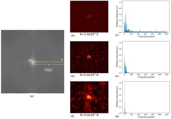
Figure 1.
Schematic diagram of spectrum sampling (a), recovery results, and the spectrograms with different K values (b–g).
2.1.3. U-Shape Neural Network
In Figure 1, It can be seen that noise exists no matter what k is. In this paper, a U-shape neural network is used for noise reduction, where the input of the model is a deconvolution-recovered image and the output label is the corresponding original object image. The total number of pairs is 1600. The model training frame and the detailed structure of the network are shown in Figure 2. The strategy of pre-training and transfer learning, with the TID2013 dataset [25], makes the model have initial image denoising ability. The encoder-decoder framework is used in the experimental model; the encoder is composed of four convblocks connected by max pool layers; the convblock, as seen from Figure 2c, consists of convolution layers, batch normalization layers, and leaky rectified linear unit (leaky ReLU) nonlinear activation functions. Then the up-sampling decoder process begins, in which the feature map from the corresponding encoder is copied and cropped so more high-frequency information is preserved for up-sampling. After that, a convolutional layer is added to produce the final result. 1600 groups of deconvolution restored images and corresponding original images are used, of which 1500 groups belong to training sets and the other 100 groups are verification sets, which contain patterns that were not involved in the training to check whether the model is overfitted. The dataset has seven kinds of samples; six of them were used for training, and another one was only used for verification. All data is recovered as images by Wiener filter deconvolution.
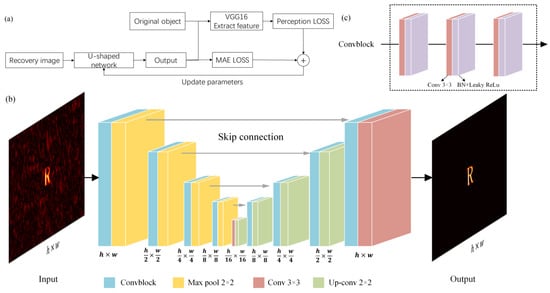
Figure 2.
(a) The frame of training; (b) architecture of the U-shaped neural network; (c) convblock.
In order to avoid blurring of the output images, perception loss (PL) combined with mean absolute error (MAE) is chosen as the loss function. MAE can be calculated from the predicted images, and original object images and PL are obtained by using VGG-16 to extract image features at different stages, which is the summation of the MSE for these image feature maps, and then summing up MSE losses at different stages.
where c, m, n, ϕ, Î, I, h, and w represent the channel, length, and width of the feature; the loss network; the value of the original object; the value of the predicted image; and the size of the inputs. We developed the network with a graphics processing unit (NVIDIA GTX 1080Ti) using the TensorFlow framework; other detailed configurations are shown in Table 1. And the average reconstruction time of the object is at the level of 100 milliseconds. During the training process, the initial learning rate is 10−3, and decreases by 10% every 10 epochs. The training epochs are 400, and the batch size is 8. Moreover, due to the position deviation between the restored image by deconvolution and the original target object, it does not meet the requirements of one-to-one correspondence between the input and output pixel positions of the denoising model, so it is necessary to translate and correct the position of the original object. In detail, we find the minimum circumscribed rectangle of the original object image and speckle reconstruction image first, then the horizontal and vertical offsets of two bounding rectangles are calculated, and the original images are translated. In order to improve the robustness of the model, we use random clipping, random rotation, and other operations on the training image to increase the amount of data. In the process of data augmentation, in order to avoid the mismatch between the input image and the label pattern, which affects the learning and training of the model, the same operation is performed on the input image and the corresponding label.

Table 1.
Computer configuration.
2.2. Experimental Setup
The experimental system schematic diagram (a) and actual optical path (b) are shown in Figure 3. d1, d2, and d3, which represent the distances among the object, diffuser, imaging lens (L2), and camera, are 420 mm, 88 mm, and 183 mm, respectively. The aperture is used to limit the diameter of the light beam so that it is just slightly larger than the object. The light source is an LED with a working wavelength range of 620 ± 10 nm. Other details of the experiment instruments are shown in Table 2.
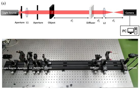
Figure 3.
Deconvolution scattering recovery imaging experimental setup. (a) schematic diagram; (b) actual optical path.

Table 2.
Instruments and parameters of the experiment.
Seven patterns used in the experiment are shown in Figure 4a–g below. These seven figures are named “Rui”, “L”, “R”, “Spines”, “Cross”, “RL”, and “Guang”, respectively.
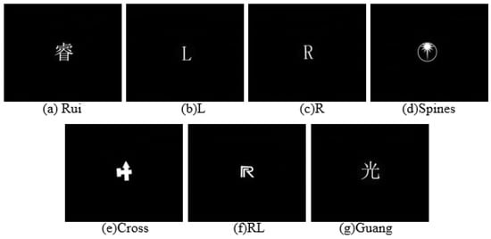
Figure 4.
Patterns of experimental samples.
3. Results and Analysis
3.1. Deconvolution with Exposure Improvement
Generally, the experimental process of deconvolution can be divided into two steps: calibration and deconvolution. Calibration involves acquiring the PSF distribution of the diffuser, which is shown in Figure 5a, from a known reference, which is a pinhole in the experiment. Then the next step for the unknown object was recording the speckles of it and calculating the original image from the speckles and PSF in the first step, which is called deconvolution. A Chinese character, “Guang”, as an instance, is chosen to be the object, and the speckle of it shown in Figure 5b is recorded. The recovery result by Weiner filter deconvolution can be seen in Figure 5c, and though the pattern restored is similar to the object to a certain degree, neither its intense massive noise nor its blurred contour are satisfactory.
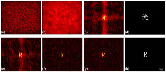
Figure 5.
(a) Speckle of PSF; (b) Speckle of object; (c) Preliminary deconvolution result; (e–g) Deconvolution results with different exposure settings, where (e) calibration exposure time is 10 ms and gain coefficient is 1.0; (f) calibration exposure time is 40 ms and gain coefficient is 1.0; (g) calibration exposure time is 10 ms and gain coefficient is 4.0; all the object speckles acquired exposure time is 40 ms and gain coefficient is 1.0; (d,h) Original objects.
Exposure time becomes the only important parameter that affects imaging because of low photo sensibility (ISO) and a zero gain coefficient. A deconvolution recovery experiment that has different exposure doses between calibration and deconvolution proves that incorrect exposure will degrade the restored images, as shown in Figure 5e, and when the exposure doses are the same (even with different exposure times and gain coefficients), the quality of the result is higher, as shown in Figure 5f,g [26].
It can be inferred that the exposure of calibration and deconvolution must be consistent. On this basis, the relationship between the image restoration quality and the exposure is shown in Figure 6. When the exposure time is more than 20 ms, both of the evaluation indicators, PSNR (Peak Signal-to-Noise Ratio) and SSIM (Structural Similarity) [27], approximately reach the peak value.
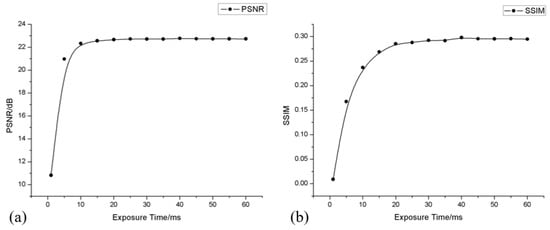
Figure 6.
Relationship curve between image quality and exposure time without gain, measured by PSNR (a) and SSIM (b).
The reconstructed image quality is influenced by the size of the pinhole in calibration. The experimental results of deconvolution with different sizes of pinholes can be seen in the figure below. Figure 7a–c represent the deconvolution recovery results of pinholes with diameters of 190 μm, 140 μm, and 90 μm, respectively. It can be seen that as the size of the pinholes decreases, the contrast of the pattern keeps increasing, and the outline becomes clearer. Moreover, SSIM and PSNR are used to evaluate the image quality, and as shown in the Table 3 below, the results generally support the above observations. Therefore, the smallest pinhole (Φ = 90 μm) is chosen as an optimal calibration sample to acquire the PSF of the diffuser in subsequent experiments.

Figure 7.
Restored results of deconvolution with different sizes of pinholes (sample “R” is taken as an example and by the same K, 2 × 10⁷). (a–c) represent the deconvolution recovery results of pinholes with diameters of 190 μm, 140 μm, and 90 μm, respectively.

Table 3.
Instruments and parameters of the experiment.
3.2. Optimum Seeking Method of Parameter K
At first, 20 observers were invited to obtain the approximate range of optimal values for K corresponding to every object listed in Figure 4, as shown in Table 4 below.

Table 4.
The approximate range of K for every object.
To obtain the precise optimal K value quickly, a novel quality evaluation function for restored images without reference information, PEF, is provided. Furthermore, the edge frequency intervals of seven objects are measured, which are shown in Table 5. In order to facilitate processing and description, we have normalized the coordinates. The intersection of statistical interval distributions is used as the final edge frequency interval, which is [0.005, 0.03]. We believe that this is representative of other images with similar complexity and distribution.

Table 5.
The range of edge frequency of every object.
Based on PEF, according to 2.2.2, an optimal K-value seek method is presented. The detailed algorithm flow, as shown in Figure 8. First, the exposure-optimized speckle pattern and the PSF distribution are inputs. Secondly, K is iterated incrementally with a variable step size ΔK and deconvoluted with a Wiener filter, and PEF is calculated based on the recovery results. The initial value K0 is 103, and the ΔK is 2i × 103, which ensure coverage for all the approximate ranges in Table 4. If the PEF(Ki) of the iteration i is decreasing and less than half the sum of the initial and maximum values, the iteration is terminated. The relationship between data log(Ki) and PEF(Ki) is fitted with a Gaussian function that is unimodal to find the peak transverse coordinate μ. Finally, K is taken as μ and deconvoluted to get the recovered image of an unknown object speckle. The fitting curve of PEF(K)–log(K) and the optimized restored result are shown in Figure 9.
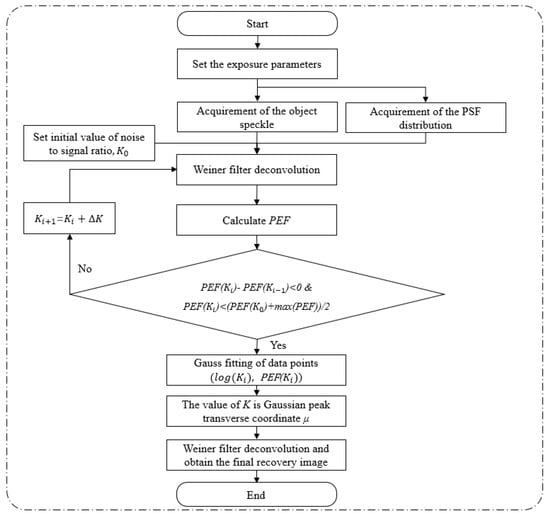
Figure 8.
The flowchart of optimal K-value Wiener filter deconvolution scattering imaging.
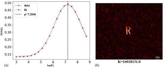
Figure 9.
PEF(K)—log(K) fitting curve (a) and recovery effect (b) (sample “R” is taken as an example).
Perform the best K-value Wiener filtering deconvolution for the speckle repetition at different resolutions. The average time consumed is shown in Table 6. Even with 500 megapixel resolution, the total time consumption is less than 42 milliseconds, which meets the real-time processing requirement of nearly 24 fps.

Table 6.
Average time consumption of each part of the optimal K-value Wiener filter deconvolution.
3.3. Denoise
Although the Wiener filter algorithm can suppress the influence of Gaussian noise, there is still a cluster-like noise distribution, so denoising is necessary as a post-process. Traditional methods such as NL-means [28] and 3D block matching (BM3D) [29] have been tried. Furthermore, the results of two traditional methods are shown in Figure 10b,c. In recent years, research on model-based noise removal has become more prominent. For example, the denoising method based on the total variation (TV) model is combined with inertial proximal ADMM [30] or overlapping group sparsity [31]. The denoised effect of the above two methods is shown in Figure 10d,e below. These methods usually define the denoising task as an optimization problem based on maximum a posteriori (MAP), which has strong mathematical derivation, but the performance of image restoration under the noise intensity in this experiment is significantly insufficient. In addition, due to the high complexity of iterative optimization, it is usually time-consuming. Compared to the raw recovery image in Figure 10a, the NL-means, BM3D, and model-based procedures are all invalid where the noise is still visible. Therefore, a convolutional neural network with a U-shape network structure is inserted into the recovery program as a post-process and achieves the great results seen in Figure 11. It is worth mentioning that good noise removal results have been achieved for both untrained cases (‘the Guang’) and untrained cases (the other patterns). In addition, even if the speckles are acquired at different areas of the same diffusor that are out of the original OME range or the diffusor is replaced, the image quality can still be improved to a high level after inputting the result of the deconvolution calculation into the model, as can be seen in Figure 12. These image pairs are also added to the validation set.

Figure 10.
Noise removal effects of different methods. (a) Restoration with deconvolution; (b) NL-means; (c) BM3D; (d) TV model with ADMM; and (e) TV model combined with overlapping group sparsity (sample “RL” is taken as an example).
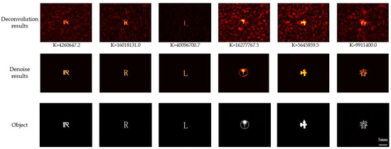
Figure 11.
The denoise results of trained samples, including “RL”, “R”, “L”, “Spines”, “Cross” and “Rui”.

Figure 12.
Noise removal effects of different methods. (a) Restoration with deconvolution (K = 209,085,916.7); (b) results from verification sets that were not added to training; (c) result from speckles acquired at different times with scatter plates from different batches; (d) original object.
Table 7 counts the PSNR and SSIM values of images before and after denoising under different conditions. Not only has the noise in the image been reduced significantly, but the brightness of the target pattern has also been improved and enhanced; these two indicators have improved by 27.3% and 186.7%, respectively. Furthermore, the noise removal of the deconvolution result is not limited by the optical memory effect.

Table 7.
Average scores of different image qualities.
The distribution of noise does not conform to the Gaussian distribution of common noise in the field of digital image processing, as shown in Figure 13, but is more in line with the Rayleigh distribution. Therefore, a more effective denoising tool is needed. Different from denoising methods based on Gaussian noise models, when we transform the method of image restoration from denoising to segmentation and use a U-shaped model to separate the real pattern from the noise, good results have been achieved.
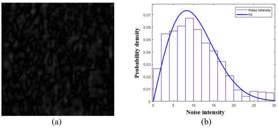
Figure 13.
Distribution of noise in the recovery with deconvolution. (a) Noise in the deconvolution results; (b) distribution of the noise.
4. Conclusions
In conclusion, this paper presents an exposure improved and optimal K-value Wiener filtering deconvolution method to realize denoising and contracting in scattering image restoration. The experimental result shows that, with the assistance of PEF, the robustness and quality of deconvolution technology have been improved, and the time consumption has been reduced to 41.5 ms (≈24 fps) with five-megapixel resolution, which means that real-time recovery imaging is possible. It is also further explored the noise processing in scattering imaging; the PSNR and SSIM of the images after denoising have been improved by 27.3% and 186.7%, respectively, and the resulting model not only has effective denoising ability but also has good generalization performance. This further expands the application potential of convolution recovery imaging. In addition, the provided method is more conducive to exploring the physical meaning of the mapping from speckle to object image in three steps.
The performance of the provided method is still insufficient for the restoration of weak light scenes or very complex patterns, such as slight deformations of the patterns. It depends on the subsequent modification and a more novel and efficient network structure to achieve better image denoising and enhancement. With a deeper understanding of the physical characteristics of the scattering process and the progress of the deep learning model and the development of computer hardware, real-time and high-quality scattering imaging recovery will be within reach.
Author Contributions
Conceptualization, Z.C., W.L., and J.W.; methodology, Z.C. and W.L.; software, Z.C. and W.L.; validation, Z.C. and H.W.; formal analysis, Z.C.; investigation, Z.C. and H.W. writing—original draft preparation, Z.C.; writing—review and editing, Z.C. and J.W.; visualization, Z.C.; supervision, J.W.; funding acquisition, J.W. All authors have read and agreed to the published version of the manuscript.
Funding
Guangdong Science and Technology Department (2019B010152001, 2020B0404030003).
Institutional Review Board Statement
Not applicable.
Informed Consent Statement
Not applicable.
Data Availability Statement
The data that support the findings of this study are available from the corresponding author upon reasonable request.
Conflicts of Interest
The authors declare no conflict of interest.
References
- Wiersma, D.S. Disordered photonics. Nat. Photonics 2013, 7, 188–196. [Google Scholar] [CrossRef]
- Wang, X.; Jin, X.; Li, J. Prior-free position detection for large field-of-view scattering imaging. Photonics Res. 2020, 8, 920–928. [Google Scholar] [CrossRef]
- Vellekoop, I.M.; Mosk, A.P. Focusing coherent light through opaque strongly scattering media. Opt. Lett. 2007, 32, 2309–2311. [Google Scholar] [CrossRef] [PubMed]
- He, H.; Guan, Y.; Zhou, J. Image restoration through thin turbid layers by correlation with a known object. Opt. Express 2013, 21, 12539–12545. [Google Scholar] [CrossRef] [PubMed]
- Han, T.; Peng, T.; Li, R.; Wang, K.; Sun, D.; Yao, B. Extending the Imaging Depth of Field through Scattering Media by Wavefront Shaping of Non-Diffraction Beams. Photonics 2023, 10, 497. [Google Scholar] [CrossRef]
- Yaqoob, Z.; Psaltis, D.; Feld, M.S.; Yang, C. Optical phase conjugation for turbidity suppression in biological samples. Nat. Photonics 2008, 2, 110–115. [Google Scholar] [CrossRef]
- Vellekoop, I.M.; Cui, M.; Yang, C. Digital optical phase conjugation of fluorescence in turbid tissue. Appl. Phys. Lett. 2012, 101, 081108. [Google Scholar] [CrossRef]
- Shen, Y.; Liu, Y.; Ma, C.; Wang, L.V. Focusing light through biological tissue and tissue -mimicking phantoms up to 9.6cm in thickness with digital optical phase conjugation. J. Biomed. Opt. 2016, 21, 085001. [Google Scholar] [CrossRef]
- Popoff, S.M.; Lerosey, G.; Carminati, R.; Fink, M.; Boccara, A.C.; Gigan, S. Measuring the Transmission Matrix in Optics: An Approach to the Study and Control of Light Propagation in Disordered Media. Phys. Rev. Lett. 2010, 104, 100601. [Google Scholar] [CrossRef]
- Mounaix, M.; Andreoli, D.; Defienne, H.; Volpe, G.; Katz, O.; Grésillon, S.; Gigan, S. Spatiotemporal Coherent Control of Light through a Multiple Scattering Medium with the Multispectral Transmission Matrix. Phys. Rev. Lett. 2016, 116, 253901. [Google Scholar] [CrossRef]
- Boniface, A.; Mounaix, M.; Blochet, B.; Piestun, R.; Gigan, S. Transmission-matrix-based point-spread-function engineering through a complex medium. Optica 2017, 4, 54–59. [Google Scholar] [CrossRef]
- Sun, Y.; Shi, J.; Sun, L.; Fan, J.; Zeng, G. Image reconstruction through dynamic scattering media based on deep learning. Opt. Express 2019, 27, 16032–16046. [Google Scholar] [CrossRef] [PubMed]
- Guo, E.; Zhu, S.; Sun, Y.; Bai, L.; Zuo, C.; Han, J. Learning-based method to reconstruct complex targets through scattering medium beyond the memory effect. Opt. Express 2020, 28, 2433–2446. [Google Scholar] [CrossRef]
- Sun, Y.; Wu, X.; Shi, J.; Zeng, G. Scattering-Assisted Computational Imaging. Photonics 2022, 9, 512. [Google Scholar] [CrossRef]
- Bertolotti, J.; Van Putten, E.G.; Blum, C.; Lagendijk, A.; Vos, W.L.; Mosk, A.P. Non-invasive imaging through opaque scattering layers. Nature 2012, 491, 232–234. [Google Scholar] [CrossRef]
- Katz, O.; Heidmann, P.; Fink, M.; Gigan, S. Non-invasive single-shot imaging through scattering layers and around corners via speckle correlations. Nat. Photonics 2014, 8, 784–790. [Google Scholar] [CrossRef]
- Eitan, E.; Scarcelli, G. Optical imaging through dynamic turbid media using the Fourier-domain showercurtain effect. Optica 2016, 3, 71–74. [Google Scholar]
- Zhuang, H.; He, H.; Xie, X.; Zhou, J. High speed color imaging through scattering media with a large field of view. Sci. Rep. 2016, 6, 32696. [Google Scholar] [CrossRef]
- Li, G.; Yang, W.; Wang, H.; Situ, G. Image Transmission through Scattering Media Using Ptychographic Iterative Engine. Appl. Sci. 2019, 9, 849. [Google Scholar] [CrossRef]
- Feng, S.; Kane, C.; Lee, P.A.; Stone, A.D. Correlations and Fluctuations of Coherent Wave Transmission through Disordered Media. Phys. Rev. Lett. 1988, 61, 834–837. [Google Scholar] [CrossRef]
- Freund, I.; Rosenbluh, M.; Feng, S. Memory Effects in Propagation of Optical Waves through Disordered Media. Phys. Rev. Lett. 1988, 61, 2328–2331. [Google Scholar] [CrossRef] [PubMed]
- Lucy, L.B. An iterative technique for the rectification of observed distributions. Astron. J. 1974, 79, 745. [Google Scholar] [CrossRef]
- Fan, J.; Koo, J.-Y. Wavelet deconvolution. IEEE Trans. Inf. Theory 2002, 48, 734–747. [Google Scholar] [CrossRef]
- Strakhov, V.N.; Vorontsov, S.V. Digital image deblurring with SOR. Inverse Probl. 2008, 24, 025024. [Google Scholar] [CrossRef]
- Ponomarenko, N.; Ieremeiev, O.; Lukin, V.; Egiazarian, K.; Jin, L.; Astola, J.; Vozel, B.; Chehdi, K.; Carli, M.; Battisti, F.; et al. Color image database TID2013: Peculiarities and preliminary results. In Proceedings of the European Workshop on Visual Information Processing, Paris, France, 10–12 June 2013; pp. 106–111. [Google Scholar]
- Chen, Z.; Li, W.; Wu, H.; Wang, J. A Real-time Scattered Image Restoration Technique Optimized by Deconvolution and Exposure Adjustment. In Proceedings of the 4th International Conference on Intelligent Control, Measurement and Signal Processing, Hangzhou, China, 8–10 July 2022; pp. 803–807. [Google Scholar]
- Hore, A.; Ziou, D. Image quality metrics: PSNR vs. SSIM. In Proceedings of the 20th International Conference on Pattern Recognition, Istanbul, Turkey, 23–26 August 2010; pp. 2366–2369. [Google Scholar]
- Buades, A.; Coll, B.; Morel, J.M. Non-local means denoising. Image Process. Line 2011, 1, 208–212. [Google Scholar] [CrossRef]
- Dabov, K.; Foi, A.; Katkovnik, V.; Egiazarian, K. Image Denoising by Sparse 3-D Transform-Domain Collaborative Filtering. IEEE Trans. Image Process. 2007, 16, 2080–2095. [Google Scholar] [CrossRef]
- Li, P.; Chen, W.; Ng, M.K. Compressive total variation for image reconstruction and restoration. Comput. Math. Appl. 2020, 80, 874–893. [Google Scholar] [CrossRef]
- Adam, T.; Paramesran, R. Image denoising using combined higher order non-convex total variation with overlapping group sparsity. Multidimens. Syst. Signal Process. 2019, 30, 503–527. [Google Scholar] [CrossRef]
Disclaimer/Publisher’s Note: The statements, opinions and data contained in all publications are solely those of the individual author(s) and contributor(s) and not of MDPI and/or the editor(s). MDPI and/or the editor(s) disclaim responsibility for any injury to people or property resulting from any ideas, methods, instructions or products referred to in the content. |
© 2023 by the authors. Licensee MDPI, Basel, Switzerland. This article is an open access article distributed under the terms and conditions of the Creative Commons Attribution (CC BY) license (https://creativecommons.org/licenses/by/4.0/).