Communication

Waveguide-Integrated Ge/Si Avalanche Photodiode with Vertical Multiplication Region for 1310 nm Detection

1
Institute of Microelectronics, Chinese Academy of Sciences, Beijing 100029, China
2
School of Electronic Electrical and Communication Engineering, University of Chinese Academy of Sciences, Beijing 100049, China
*
Author to whom correspondence should be addressed.
Photonics 2023, 10(7), 750; https://doi.org/10.3390/photonics10070750
Submission received: 31 May 2023 / Revised: 20 June 2023 / Accepted: 26 June 2023 / Published: 29 June 2023

Abstract

:
Ge/Si separate absorption, charge, and multiplication avalanche photodiodes (SACM APDs) coupled with waveguides have shown significant potential as high-sensitivity, low-noise, and high-speed photodetectors for optical communications. In this study, we present a waveguide-integrated Ge/Si SACM APD fabricated on an eight-inch silicon photonics platform. The device exhibits a primary responsivity of 0.68 A/W at the unit gain voltage of 6 V for the O-band (1310 nm) wavelength, with a 10 μm-long and 1 μm-wide Ge layer. Additionally, the device demonstrates a 3 dB bandwidth of 25.7 GHz, with an input optical power of −16.8 dBm. The largest gain bandwidth product (GBP) is 247 GHz at a gain of 9.64 and a bias voltage of 15.7 V. The eye diagram is open at the bias voltage of 16 V, with a capacity to receive 28 Gbps of data. This APD shows potential for application in high-speed data transmission systems.

1. Introduction

The demand for data communication is rapidly increasing, driven by emerging applications such as cloud services, artificial intelligence, and the Internet of Things. These applications require high-performance computers, 5G communication, and hyper-scale data centers [1]. Silicon photonics is a popular option for optical interconnects due to its unique advantages of CMOS (Complementary Metal-Oxide Semiconductor) compatibility, low power consumption, and high bandwidth [2,3,4]. Optical interconnection in data centers has been very successful due to the trend of low power consumption and high bandwidth, making high-performance photonics devices essential for achieving high sensitivity in data transmission links [5,6,7]. However, conventional p-i-n photodiodes are insufficient to meet the demands of optical interconnect systems. Avalanche photodiodes (APDs) with internal gain can significantly increase receiver sensitivity, relaxing the bandwidth requirements of optics and electronics, as well as link and power budgets [1,8]. While III-V APDs are widely used in optical communication and interconnection due to their low dark current and high bandwidth, their high cost and inability to integrate monolithically with microelectronic devices hinder their further promotion [9]. Additionally, III-V APDs suffer from a high excess noise factor due to the intrinsically high ratio of the ionization coefficient from holes and electrons (denoted as K-value). Fortunately, silicon germanium APDs are a promising choice due to their compatibility with the CMOS process and the excellent avalanche multiplication performance of silicon [10].
In recent years, waveguide-integrated Ge/Si APDs have been intensively explored to improve the gain bandwidth product (GBP) and the sensitivity [1,2,6]. SACM APDs have been introduced to address the high dark current issue in Ge APDs [10,11] or vertical p-i-n [12,13], which is caused by a strong electric field in the germanium layer. Firstly, in order to decrease the excess noise for the present Ge/Si APD, the electric field, EGe, in germanium layer should be below 2 × 10⁵ V/cm to avoid any ionization [14]. EGe should be higher than 1 × 10⁴ V/cm, so that the photo-generated carriers can drift quickly at their saturation velocity [15]. Reducing the thickness of the charge layer is one way to control the electrical field inside the Ge layer for the high dark current, such as 50 nm and 100 nm thicknesses of the charge layer [16,17,18], which has a 3 dB bandwidth of 6.24 (GBP 432 GHz) at −31 V. Another approach is to form the charge layer using a thick epitaxial Si layer with a P-type dopant. However, the thick epi-Si can deteriorate light coupling from the Si waveguide into the Ge region and increase the operating voltage (>20 V) and the complexity of the process. To address this, a 70 nm-deep trough is etched before the Ge-epi to form the charge layer, which strengthens the electric field in the germanium layer and changes the butt-coupling to end-coupling to increase the coupling efficiency [19,20]. The 3 dB bandwidth of these types is 13.8 GHz and 32 GHz at −12 V (gain > 8), respectively.
Recently, a lateral SACM Ge/Si APD with high responsivity at unit gain and a low dark current has been demonstrated by introducing two shallow trenches at both sides of the germanium strip in the active region [6]. This process has a 3 dB bandwidth of 48 GHz at −14 V (GBP 615 GHz); however, it is complex, and more efforts should be made to reduce the dislocation density.
In addition to the structures mentioned above, a Ge/Si APD in a three-terminal layout has been demonstrated [21], which can achieve low voltage operation by independently controlling the electric field in the germanium region and the multiplication region. This process has a 3 dB bandwidth of 18.9 GHz. However, Si epitaxy is still required, and metal contacts on the germanium layer are harmful to the responsivity. Besides, there are some other optoelectronic materials which can be further developed [22]. Therefore, there is still a strong desire to further improve the bandwidth and gain of Ge/Si APDs to meet the demands of data transmission applications.
In this work, we present a vertical SACM Ge/Si APD designed with simplified fabrication processes that do not require deep-top Si etching or an epi-Si layer. The epitaxial germanium layer is directly grown on the 220 nm top silicon, and the width of the charge layer is 300 nm. In the following sections, we discuss the static characteristics of the APD, including the dark current and multiplication gain, as well as the small-signal characteristics, such as the 3 dB bandwidth. Our results show that the primary responsivity is 0.68 A/W at the unit gain voltage of 6 V bias at the O-band (1310 nm) wavelengths. Furthermore, a 3 dB bandwidth of 25.7 GHz can be achieved with an input optical power of −16.8 dBm at −15.7 V.

2. Design and Fabrication

A structure with a 1 μm-wide and 10 μm-long Ge-epi was formed in the low-voltage vertical waveguide-integrated Ge-Si APD. As Figure 1 shows, the structure consists of a germanium absorption layer, which is located at the top silicon, a silicon charge layer called Pul (P-type ultra-low doping concentration) under two sides of the Ge layer, which is shown in yellow, and a silicon multiplication layer between the P-contact layer and the silicon charge layer. While germanium is an excellent absorption material due to its high k-factor (with a value of 1.0), it is not a good medium for carrier multiplication. As a result, the multiplication happening in the germanium layer is noisy. On the other hand, silicon is among the best semiconductors for carrier multiplication, with one of the lowest k-factors (with a value of 0.02) [23,24]. Figure 1a shows the 3D schematic of the fabricated waveguide-integrated SACM vertical Ge/Si APD. The waveguide-integrated SACM vertical Ge/Si APD was fabricated on an 8-inch SOI wafer with a 220 nm-thick p-type <100>-oriented top Si layer and a 3 μm-thick buried oxide (BOX) layer. Figure 1c shows the FIB cross-section of the APD.
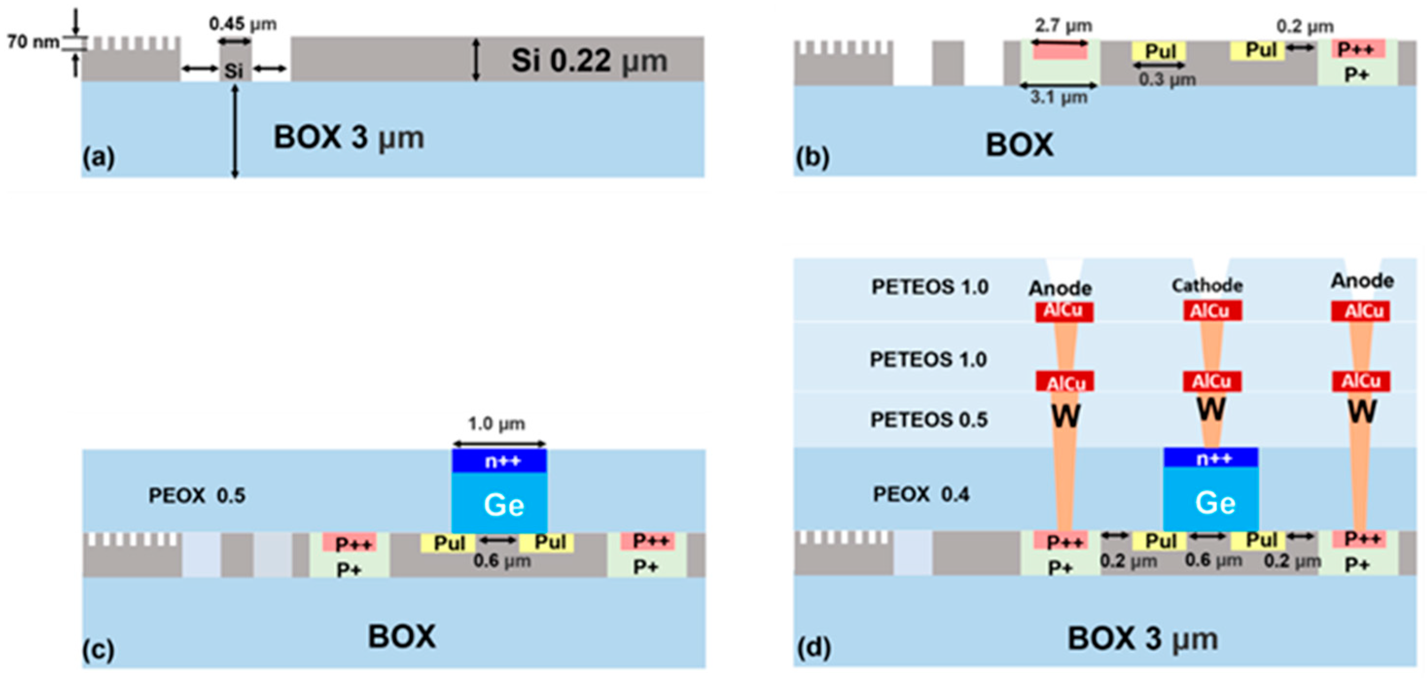
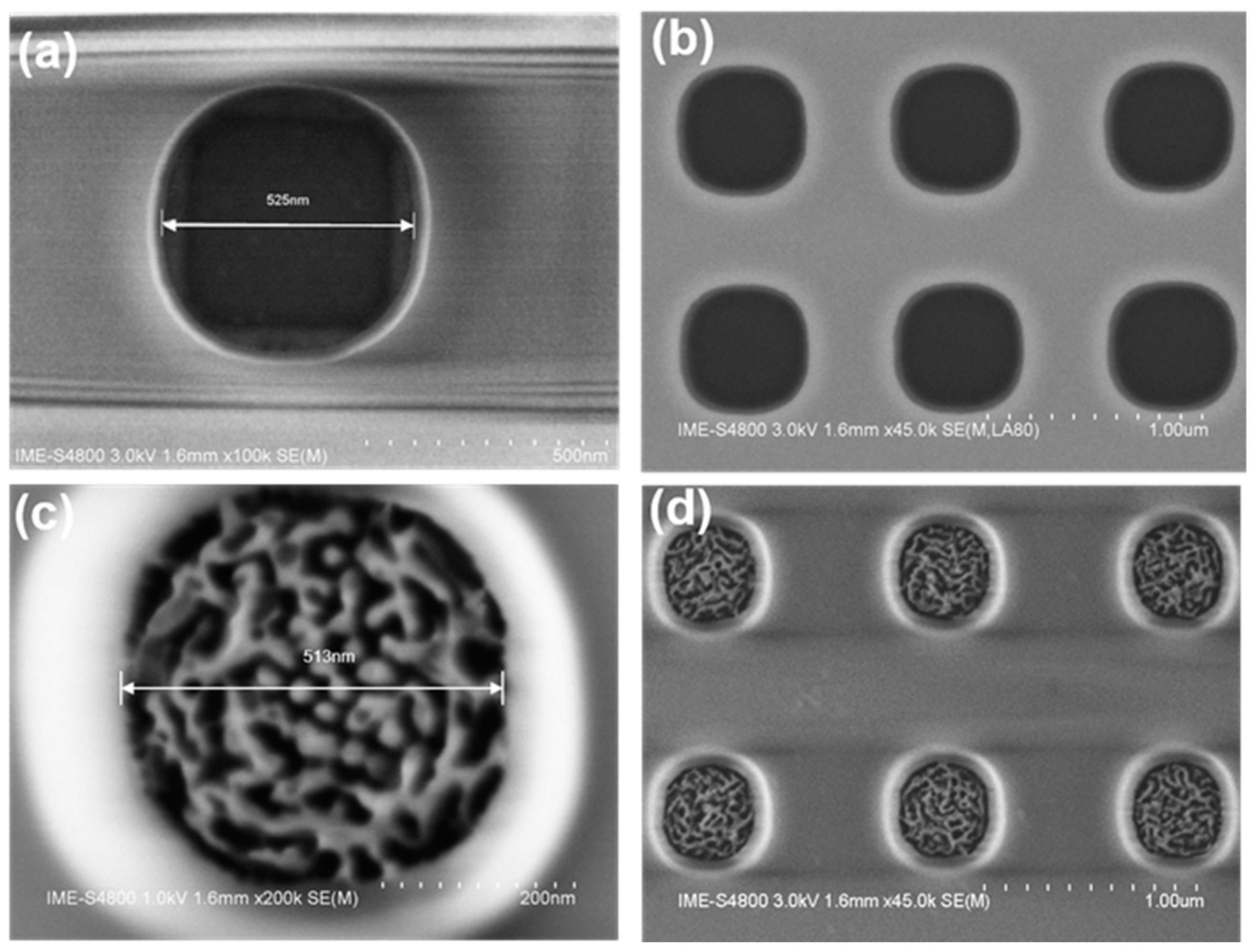
Figure 2 shows the critical process used to fabricate the device. Firstly, the channel waveguide was fabricated by a 220 and 70 nm-deep dry etching. The nominal width of the channel waveguide was designed to be 450 nm to support the single mode [17,25]. As shown in Figure 1b, the curved sidewall of the waveguide was caused by high-temperature annealing under hydrogen ambient conditions, which were developed to reduce the scattering loss [26,27]. Then, the grating was formed by a 220 nm-deep dry etching. The designed grating had a period of 490 nm and duty of 0.5 to coupling 1310 nm light from the fiber to the waveguide, as shown in Figure 2a. Secondly, three different doping concentrations with boron were implanted to the charge layer and a specific region on the top silicon layer, which formed p+ and p++ charge layers, followed by the rapid thermal annealing to activate those ions and repair the implantation damage, as shown in Figure 2b. Thirdly, a 1 μm-thick oxide was deposited on the wafer by the plasma-enhanced chemical vapor deposition (PECVD) technology, as shown in Figure 2c. Then, the chemical mechanical polish (CMP) process was used to planarize the wafer, and the thickness of the oxide was reduced to 500 nm. After etching out a 10 μm × 1.0 μm × 0.5 μm (length × width × depth) window and careful cleaning, Ge epitaxial growth was conducted by the reduced pressure chemical vapor deposition (RPCVD) technology. Another CMP step was used to remove the overgrown part of the germanium layer and to planarize the wafer, so after the over-polishing during the CMP, the remaining Ge was about 400 nm. Then, the germanium layer was heavily doped by ion implantation to form n-type ohmic contacts. After that, the topography SEM image in Figure 3a,b was obtained, which shows that the hole diameter was 525 nm. Finally, Figure 2d shows that the first and second metallization and passivation were accomplished by the standardized back-end-of-the-line (BEOL) process. The detailed processes of this step were as follows: After finishing the heavily doped ion implantation, a 500 nm-thick oxide was deposited on the wafer by plasma-enhanced tetraethyl orthosilicate (PETEOS) technology. Through lithography, dry etching, and other processes, tungsten contact holes were formed in this layer, and it was necessary to emphasize that there was a certain amount of over-etching to ensure that the tungsten could be contacted on the Ge layer. Then, the CVD technology filled the entire contact hole with tungsten metal. After that, the CMP step was used to remove the overgrown part of the tungsten metal layer and to planarize the wafer. Then, a layer of aluminum copper (AlCu) alloy was immediately deposited on the wafer surface, in which the Cu atoms can act as a bond to the aluminum grains and thus prevent the electromigration of aluminum. Most of the area was etched by photolithography, dry etching, and other processes, and only the metal in the interconnect area was retained. The process of M2 was similar to M1; however, the connection between M1 and M2 is especially important, so the processes must be carefully carried out. Finally, the wafer was annealed at a high temperature of about 400 °C in a nitrogen atmosphere to make the Al and Cu atoms in the AlCu alloy better fuse and further enhance the adhesion between the metal and the oxide. The two metal structures were similar to the devices shown in [28,29]. After the first metal, we can see from the topography SEM images in Figure 3c,d that the inner hole diameter of the AlCu layer was 513 nm.

3. Device Characterization

3.1. Static Photoresponse

Figure 4 shows the measured I–V curves at room temperature for the fabricated waveguide Ge/Si APD when operating at 1310 nm, with different optical powers varying from −5.8 to −16.8 dBm. As shown in Figure 4a, the dark current started at a value of 49 nA at 0.1 V and began to rapidly increase at 11.1 V, and then reached 450 μA at around 15.6 V, indicating that the avalanche multiplication occurred at around 11.1 V. The breakdown voltage of the present APD was determined to be around 15.6 V according to the current limit. In this paper, we set a current limit, so 15.6 V was defined as the breakdown voltage. The dark current of the measurement system was affected by both the leakage current and the parasitic capacitance. This resulted in oscillation at a low bias between 0 and 4 V. As the reverse voltage increased from 4 to 10 V, the dark current increased nearly exponentially. This phenomenon is related to the gradual depletion of the germanium layer above the silicon layer. Under the influence of the strong electric field, which was generated due to internal multiplication and tunneling, a large number of carriers were produced, resulting in a high dark current. Therefore, the emitted noise during the internal multiplication process significantly contributed to the overall dark current, serving as the primary limiting factor in the APD operation. It is well-known that the epitaxial growth of the Ge region within Si cavities introduces a lattice mismatch of approximately 4.2%. Consequently, this leads to the presence of extensive arrays of misfit and threading dislocations, resulting in elevated dark current levels. However, enhancing the crystalline quality of the material and subsequently reducing the dark current levels can be achieved through the implementation of optimized device geometries, advanced material integration strategies, or improved epitaxial post-processing treatments. The experimental setup for measuring the dark current is illustrated in Section 3.2.
The photoresponse of the APD was evaluated at a wavelength of 1310 nm by varying the input optical powers. The photoresponsivity of the device was determined from the current–voltage curves using the following equation: R = ( I p h I d ) / P i n , where I p h and I d represent the photocurrents and dark currents, respectively, and P i n represents the optical power coupled to the photodetector, accounting for the grating coupler loss. The gradual increase in the photocurrent from 0 V to 4 V can potentially be attributed to the presence of the hetero-junction barrier. However, the subsequent rise in the photocurrent from 4 V to 11.1 V was primarily attributed to the enhanced carrier collection efficiency and avalanche multiplication. At a reverse voltage of 11.1 V, it is expected that the germanium region will become fully depleted. Among the five different input optical powers tested, it was evident that higher incident powers resulted in larger photocurrent values for the device. The experimental setup for measuring the photocurrent is illustrated in Section 3.2.
Figure 4b shows the calculated responsivity of the APD, obtained by dividing the photocurrent by the input optical power. The poor responsivity under a low bias (0–1 V) can be attributed to various factors. Firstly, the weak electric field inside the germanium region hampered the separation of photogenerated electron–hole pairs. Besides, the Ge/Si alloy, formed by Ge and Si atom interdiffusion during epitaxy and annealing, had a much lower light absorption coefficient, and consequently deteriorated the responsivity [30,31]. It was shown that the primary responsivity, R O , of the present APD was about 068 A/W at the unit gain voltage of 6 V. Further improvement of the responsivity can be achieved by reducing the Ge crystal defects and optimizing the structure [19]. The responsivity of the fabricated APD exhibited an increasing trend with an increment in the reverse bias, peaking at a maximum value of 6.56 A/W when Vbias was approximately 15.6 V under an input optical power of −16.8 dBm. However, determining the precise reverse voltage at which avalanche multiplication occurred was challenging. As the reverse bias continued to rise, the responsivity gradually declined due to the dark current increasing at a faster rate compared to the total current. Additionally, it was observed that the responsivity enhanced with the decreasing input optical power.
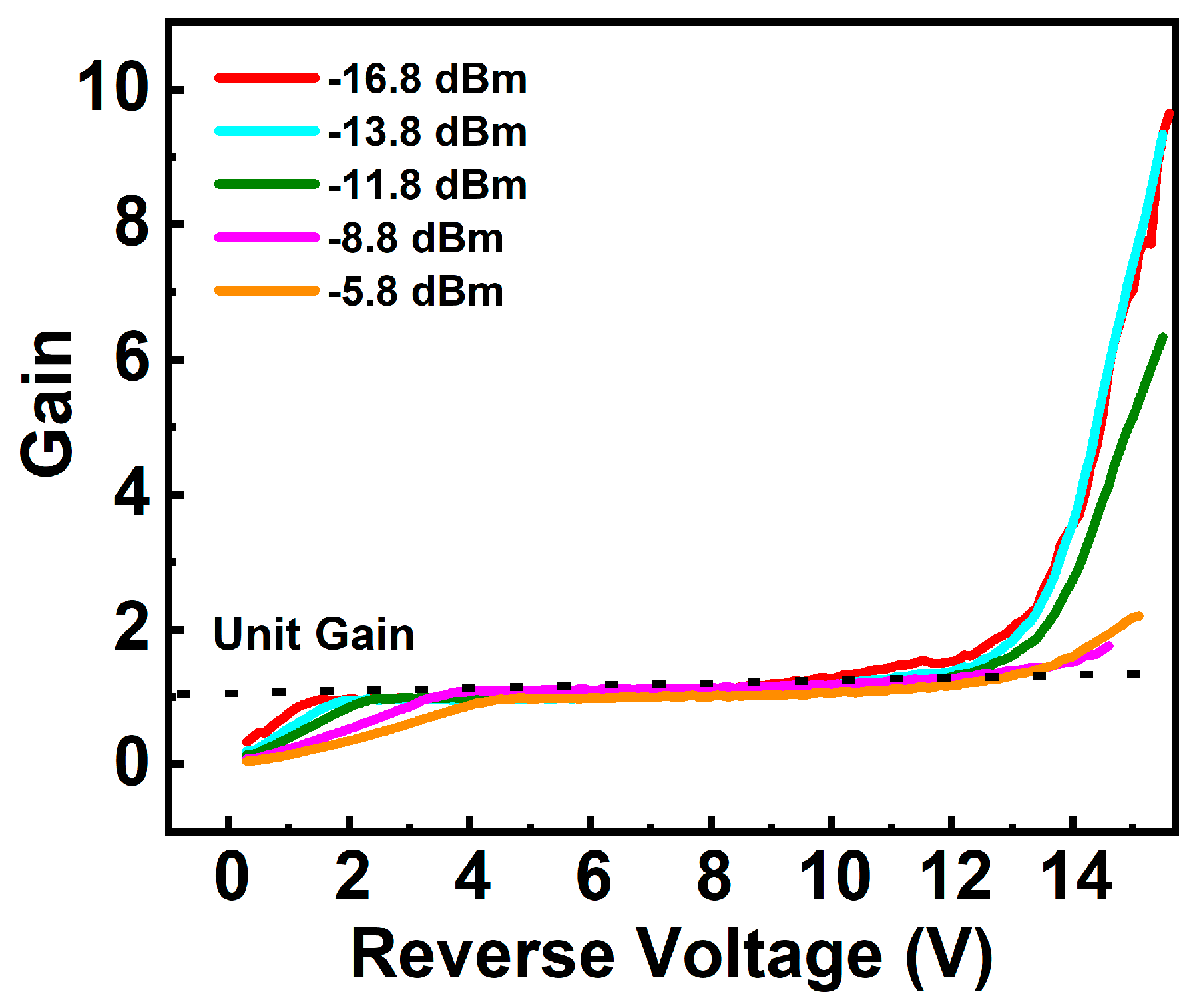
Gain (G) as a function of the applied reverse voltage and input powers is shown in Figure 5. The gain, defined as the ratio of the photoresponsivity at a specific voltage and the reference photoresponsivity, was calculated as: G V = R ( V ) / R 0 , where R 0 represents the primary responsivity. The unit gain voltage was set at 6 V in this work. The primary responsivity of the fabricated device had a mean value of 0.68 A/W. At 15.6 V, under optical powers of −5.8 dBm, −8.8 dBm, −11.8 dBm, −13.8 dBm, and −16.8 dBm, the gain reached maximum values of 2.2, 1.75, 6.33, 9.33, and 9.64, respectively. The gain was not so large, mainly because of the process and the dopant distribution of the charge region in the diode [18,32]. Furthermore, the gain demonstrated an upward trend as the optical power decreased, which was due to the reduction of the internal electrical field in the multiplication region due to the finite resistance [33].

3.2. Small-Signal Characteristics

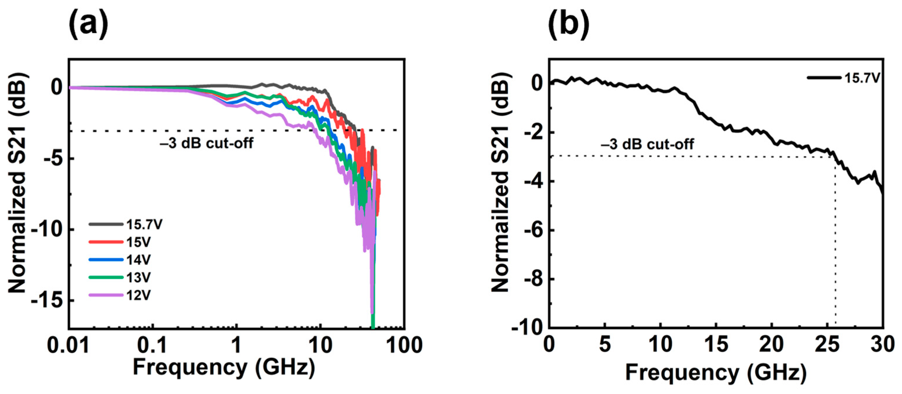
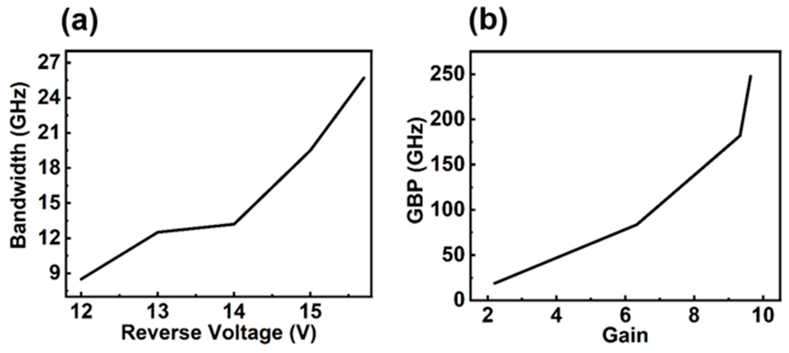
Small-signal testing was performed using a conventional RF test setup with a light-wave component analyzer (LCA) by measuring the S21 parameter in the 0.1 to 65 GHz frequency range. The experimental setup for measuring bandwidth is illustrated in Figure 6c. The type of LCA was N4373D, which is produced by Keysight company. Figure 7a shows the measured O-E frequency responses for the APD under different bias voltages. Here, we set the input optical power as −16.8 dBm. When operating with a bias voltage of 12 V, the present APD had a 3 dB bandwidth of 8.8 GHz. The bandwidth showed a slight improvement from 8.5 GHz to 13.2 GHz by increasing the bias voltage from 12 V to 14 V. Figure 7b shows that the 3 dB bandwidth was 25.7 GHz at the bias voltage of 15.7 V. In addition, the bandwidth showed a sharp increase from 13.2 GHz to 25.7 GHz when the bias voltage was changed from 14 to 15.7 V, as shown in Figure 7a. At low bias voltages, owing to the low electric field intensity inside the germanium layer, the SACM had an extremely low 3 dB bandwidth, so the generated electron–hole pairs did not reach the saturation velocity, and the bandwidth was limited by the long transmit time [28]. At a higher bias voltage, such as 15.7 V, the gain was 9.64. We know that a bandwidth enhancement at a gain of 5 or higher occurred due to the space charge effects, where the device bandwidth at high gains did not drop as quickly, even though the avalanche buildup time started to affect the device bandwidth [34]. Figure 8b shows that at different gains, the changes in the gain bandwidth product varied. We found that the largest GBP was 247 GHz, with a gain of 9.64 at a voltage of 15.7 V.
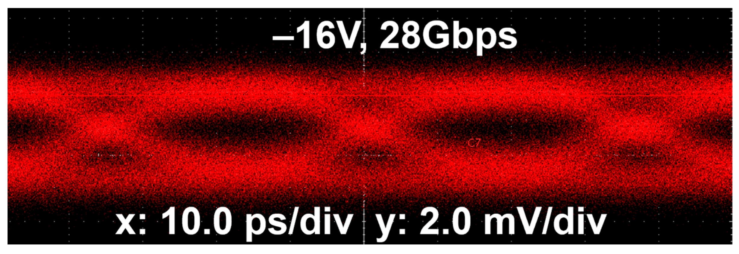
Here, the large-signal eye diagrams were measured with the present waveguide Ge/Si APDs without a transimpedance amplifier (TIA), for which the optimized operating voltage was around −16 V and the input optical power was set to −9 dBm. The experimental setup for measuring eye diagram is illustrated in Figure 6d. The output optical signal of the modulator was detected by the APD, and the electrical signal output of the APD was injected into an oscilloscope. Figure 9 shows the eye diagrams for the voltage of −16 V at 28 Gbps. The image is not clear because the dark current was high, which affected the eye diagram, as well as the limitation of the 3 dB bandwidth of the present APD and the system (which consists of the driver, the MZM, the RF cables, the bias-Tee, and the RF probe). At P i n = −9 dBm, the eye diagram was distinctly opened.

4. Benchmarking and Discussion

Epitaxial Ge-Si-based photodetectors were created in this work. However, along with the direct hetero-epitaxy approach, two other strategies also exist to achieve high-performance, on-chip photodetectors. One concerns the transfer printing [35] or layer transfer-based approaches [36,37]. This method can directly achieve ultra-high-quality, single-crystalline optical layers on diverse arbitrary optical templates for photodetection and beyond. The other is subwavelength photonic structure-enhanced photodetectors [38,39]. Table 1 provides a summary of the reported Ge/Si APDs, including the structure and process complexity and the overall performance of the APD proposed in this work by comparing the key parameters with the other reported waveguide-integrated Ge/Si APDs. Most were developed for 1550 nm, and there are a few APDs demonstrated for the O-band. As shown in Table 1, the waveguide-type APDs show great potential for achieving a high 3 dB bandwidth, which is well-known. We can see that while the dark current of the Lateral p-i-n-Ge was high, the 3 dB bandwidth was lower than that in our report [11]. In the table, vertical SACM-n(Ge) and vertical SACM-P(Ge) show the doping-type concentration of the Ge-epi. We found little research about the vertical SACM-n(Ge), but one paper reported that the GBP was 182 GHz [40], much smaller than that in our work. A waveguide-type APD with a trench on the top silicon layer increased the complexity of fabrication [6]. For example, the present Ge/Si APD with a vertical SACM structure was fabricated by using a standard 180 nm MPW process without any additional process complexities. This makes it very promising to be integrated with any other silicon photonic devices (including modulators, filters, etc.) on the same chip. However, the dark current in this paper was 450 µA at the breakdown voltage, which is higher than the device in [6]. The structure in [41] shows a high 3 dB bandwidth, however, the breakdown voltage was higher than that in the present study. One classic structure is shown in [42], reported by Sandia National Laboratories, USA. This structure showed a high bandwidth product of 432 GHz at the C band; however, the dark current was high too, and because of this element, the 10 Gbps eye diagram was not that clear. In summary, how to control the dark current and increase the 3 dB bandwidth is an important task. The dislocation density can be reduced by increasing the growth quality of the Ge and Si heterogeneous interface. Nevertheless, more efforts are still needed to further improve the sensitivity and enable the low-power and high-bit-rate data-receiving.

5. Conclusions

In this paper, a high-performance waveguide vertical SACM-n(Ge) APD was proposed without the complexity of Si epitaxy and trenches on the top Si layer. It showed an excellent primary responsivity of about 0.68 A/W at 6 V when operating at the wavelength of 1310 nm. The measured dark current was about 450 µA for the APD operating at 15.7 V; meanwhile, the corresponding 3 dB bandwidth was as high as 25.7 GHz, and the bandwidth product was 247 GHz, with a gain of 9.64 at a voltage of 15.7 V. Furthermore, 28 Gbps data-receiving was demonstrated at a reverse bias of −16 V. The low-bias and high-speed operation can enable energy-efficient optical communication and interconnect. More efforts should be made to further reduce the operating voltage as well as the dark current in future work.

Author Contributions

Conceptualization, L.Y.; methodology, L.Y. and D.L. (Daoqun Liu); formal analysis, L.Y.; investigation, L.Y.; resources, L.Y. and D.L. (Daimo Li) and P.Z.; data curation, L.Y.; writing—original draft preparation, L.Y.; writing—review and editing, L.Y. and Z.L.; visualization, L.Y.; supervision, W.W. and Z.L.; project administration, Y.Y., B.L., B.T., P.Z. and Z.L.; funding acquisition, B.T. and Z.L. All authors have read and agreed to the published version of the manuscript.

Funding

This research was funded by the National Key Research and Development Program of China (Grant No. 2018YFB2200203) and the Open Fund of the State Key Laboratory of Integrated Optoelectronics (Grant No. IOSKL2020KF06).

Institutional Review Board Statement

Not applicable.

Informed Consent Statement

Not applicable.

Data Availability Statement

The data presented in this study are available upon request from the corresponding author.

Acknowledgments

The authors acknowledge Daoqun Liu from Pengcheng Lab, ShenZhen, China, for the advice on device characterization and testing. The authors also acknowledge the Institute of Semiconductors, Chinese Academy of Sciences, Beijing, China, for their help with eye diagram testing.

Conflicts of Interest

The authors declare no conflict of interest.

References

  1. Wang, B.; Mu, J. High-speed Si-Ge avalanche photodiodes. PhotoniX 2022, 3, 8. [Google Scholar] [CrossRef]
  2. Wang, B.; Huang, Z.; Sorin, W.V.; Zeng, X.; Liang, D.; Fiorentino, M.; Beausoleil, R.G. A low-voltage Si-Ge avalanche photodiode for high-speed and energy efficient silicon photonic links. J. Light. Technol. 2019, 38, 3156–3163. [Google Scholar] [CrossRef]
  3. Wang, W.; Zhao, L.; Lu, D.; Yao, J.; Huang, W.; Liu, Y.; Little, B. Preface to the special issue on semiconductor optoelectronic integrated circuits. J. Semicond. 2021, 42, 040101. [Google Scholar] [CrossRef]
  4. Kumar, A.; Huang, Z.; Zeng, X.; Wang, B.; Liang, D.; Sorin, W.; Palermo, S. Design considerations for energy efficient DWDM PAM4 transceivers employing avalanche photodiodes. Laser Photonics Rev. 2020, 14, 2000142. [Google Scholar] [CrossRef]
  5. Hsu, Y.; Chuang, C.Y.; Wu, X.; Chen, G.H.; Hsu, C.W.; Chang, Y.C.; Tsang, H.K. 2.6 Tbit/s on-chip optical interconnect supporting mode-division-multiplexing and PAM-4 signal. IEEE Photonics Technol. Lett. 2018, 30, 1052–1055. [Google Scholar] [CrossRef]
  6. Xiang, Y.; Cao, H.; Liu, C.; Guo, J.; Dai, D. High-speed waveguide Ge/Si avalanche photodiode with a gain-bandwidth product of 615 GHz. Optica 2022, 9, 762–769. [Google Scholar] [CrossRef]
  7. Sun, C.; Wade, M.T.; Lee, Y.; Orcutt, J.S.; Alloatti, L.; Georgas, M.S.; Stojanović, V.M. Single-chip microprocessor that communicates directly using light. Nature 2015, 528, 534–538. [Google Scholar] [CrossRef] [Green Version]
  8. Li, Y.; Liu, X.; Li, X.; Zhang, L.; Li, Y.; Chen, B.; Song, J. Lateral separate absorption charge multiplication Ge-on-Si avalanche photodiode with low dark current in linear mode. Opt. Commun. 2022, 518, 128343. [Google Scholar] [CrossRef]
  9. Liu, D.; Zhang, P.; Tang, B.; Wang, W.; Li, Z. High-Performance Waveguide-Integrated Ge/Si Avalanche Photodetector with Lateral Multiplication Region. Micromachines 2022, 13, 649. [Google Scholar] [CrossRef]
  10. Benedikovic, D.; Virot, L.; Aubin, G.; Hartmann, J.M.; Amar, F.; Le Roux, X.; Vivien, L. 40 Gbps heterostructure germanium avalanche photo receiver on a silicon chip. Optica 2020, 7, 775–783. [Google Scholar] [CrossRef]
  11. Virot, L.; Crozat, P.; Fédéli, J.M.; Hartmann, J.M.; Marris-Morini, D.; Cassan, E.; Vivien, L. Germanium avalanche receiver for low power interconnects. Nat. Commun. 2014, 5, 4957. [Google Scholar] [CrossRef] [PubMed] [Green Version]
  12. Chen, H.T.; Verbist, J.; Verheyen, P.; De Heyn, P.; Lepage, G.; De Coster, J.; Roelkens, G. 25-Gb/s 1310-nm optical receiver based on a sub-5-V waveguide-coupled germanium avalanche photodiode. IEEE Photonics J. 2015, 7, 15357076. [Google Scholar] [CrossRef]
  13. Assefa, S.; Xia, F.; Vlasov, Y.A. Reinventing germanium avalanche photodetector for nanophotonic on-chip optical interconnects. Nature 2010, 464, 80–84. [Google Scholar] [CrossRef] [PubMed]
  14. Decker, D.R.; Dunn, C.N. Determination of germanium ionization coefficients from small-signal IMPATT diode characteristics. IEEE Trans. Electron Devices 1970, 17, 290–299. [Google Scholar] [CrossRef]
  15. Chen, H.T.; Verheyen, P.; De Heyn, P.; Lepage, G.; De Coster, J.; Absil, P.; Van Campenhout, J. High-responsivity low-voltage 28-Gb/s Ge pin photodetector with silicon contacts. J. Light. Technol. 2015, 33, 820–824. [Google Scholar] [CrossRef] [Green Version]
  16. Srinivasan, S.A.; Lambrecht, J.; Guermandi, D.; Lardenois, S.; Berciano, M.; Absil, P.; Van Campenhout, J. 56 Gb/s NRZ O-band hybrid BiCMOS-silicon photonics receiver using Ge/Si avalanche photodiode. J. Light. Technol. 2020, 39, 1409–1415. [Google Scholar] [CrossRef]
  17. Srinivasan, S.A.; Lambrecht, J.; Berciano, M.; Lardenois, S.; Absil, P.; Bauwelinck, J.; Van Campenhout, J. Highly sensitive 56 Gbps NRZ O-band BiCMOS-silicon photonics receiver using a Ge/Si avalanche photodiode. In Proceedings of the 2020 Optical Fiber Communications Conference and Exhibition (OFC), San Diego, CA, USA, 8–12 March 2020. [Google Scholar]
  18. Srinivasan, S.A.; Berciano, M.; De Heyn, P.; Lardenois, S.; Pantouvaki, M.; Van Campenhout, J. 27 GHz silicon-contacted waveguide-coupled Ge/Si avalanche photodiode. J. Light. Technol. 2020, 38, 3044–3050. [Google Scholar] [CrossRef]
  19. Ono, H.; Fujikata, J.; Noguchi, M.; Takahashi, H.; Shimura, D.; Yaegashi, H.; Sasaki, H. Si photonics butt-coupled waveguide germanium avalanche photodiodes with lateral SAM structures. In Proceedings of the Optical Fiber Communication Conference, Optical Society of America, San Diego, CA, USA, 3–7 March 2019; Volume 1–3. [Google Scholar]
  20. Srinivasan, S.A.; De Heyn, P.; Hiblot, G.; Chen, H.; Lardenois, S.; Pantouvaki, M.; Van Campenhout, J. Silicon-contacted waveguide integrated Ge/Si avalanche photodiode with 32 GHz bandwidth and multiplication gain > 8. In Proceedings of the 45th European Conference on Optical Communication (ECOC 2019), Dublin, Ireland, 22–26 September 2019; pp. 1–3. [Google Scholar]
  21. Zeng, X.; Huang, Z.; Wang, B.; Liang, D.; Fiorentino, M.; Beausoleil, R.G. Silicon–germanium avalanche photodiodes with direct control of electric field in charge multiplication region. Optica 2019, 6, 772–777. [Google Scholar] [CrossRef]
  22. Li, Z.; Liu, X.; Zuo, C.; Yang, W.; Fang, X. Supersaturation-Controlled Growth of Monolithically Integrated Lead-Free Halide Perovskite Single-Crystalline Thin Film for High-Sensitivity Photodetectors. Adv. Mater. 2021, 33, 2103010. [Google Scholar] [CrossRef]
  23. Kang, Y.; Liu, H.D.; Morse, M.; Paniccia, M.J.; Zadka, M.; Litski, S.; Campbell, J.C. Monolithic germanium/silicon avalanche photodiodes with 340 GHz gain–bandwidth product. Nat. Photonics 2009, 3, 59–63. [Google Scholar] [CrossRef]
  24. Wang, B.Z.; Huang, X.; Zeng, D.; Liang, M.; Fiorentino, W.V.; Sorin, W.V.; Beausoleil, R.G. 50 Gb/s PAM4 low-voltage Si-Ge avalanche photodiode. In Proceedings of the Conference on Lasers and ElectroOptics (CLEO), San Jose, CA, USA, 7–12 May 2019. [Google Scholar]
  25. Chrostowski, L.; Hochberg, M. Silicon Photonics Design: From Devices to Systems; Cambridge University Press: Cambridge, UK, 2015; pp. 98–103. [Google Scholar]
  26. Knights, A.P.; Reed, G.T.; Ribaud, K.; Lemonnier, O.; Lyan, P.; Hartmann, J.-M.; Petit-Etienne, C.; Sciancalepore, C.; Pargon, E.; Bellegarde, C. Optimization of H2 thermal annealing process for the fabrication of ultra-low loss sub-micron silicon-on-insulator rib waveguides. In Proceedings of the Silicon Photonics XIII, San Francisco, CA, USA, 27 January–1 February 2018. [Google Scholar]
  27. Reed, G.T.; Knights, A.P.; Bellegarde, C.; Pargon, E.; Sciancalepore, C.; Petit-Etienne, C.; Hughes, V.; Hartmann, J.-M.; Lyan, P. Improvement of sidewall roughness of sub-micron silicon-on-insulator waveguides for low-loss on-chip links. In Proceedings of the Silicon Photonics XII, San Francisco, CA, USA, 27 January–1 February 2018. [Google Scholar]
  28. Samani, A.; Carpentier, O.; El-Fiky, E.; Jacques, M.; Kumar, A.; Wang, Y.; Plant, D.V. Highly sensitive, 112 Gb/s O-band waveguide coupled silicon-germanium avalanche photodetectors. In Proceedings of the 2019 Optical Fiber Communications Conference and Exhibition (OFC), San Diego, CA, USA, 3–7 March 2019; pp. 1–3. [Google Scholar]
  29. Carpentier, O.; Samani, A.; Jacques, M.; El-Fiky, E.; Alam, M.S.; Wang, Y.; Plant, D. High gain-bandwidth waveguide coupled silicon germanium avalanche photodiode. In Proceedings of the Conference on Lasers and Electro-Optics, OSA Technical Digest, Washington, DC, USA, 10–15 May 2020; p. STh4O-3. [Google Scholar]
  30. Zhu, Y.; Yang, Q.; Wang, Q. Effect of Si-Ge interdiffusion on the waveguide properties of SiGe-Si MQW photodetector. IEEE J. Quantum Electron. 1997, 33, 761–764. [Google Scholar]
  31. Luong, T.K.P.; Dau, M.T.; Zrir, M.A.; Stoffel, M.; Le Thanh, V.; Petit, M.; Murota, J. Control of tensile strain and interdiffusion in Ge/Si(001) epilayers grown by molecular-beam epitaxy. J. Appl. Phys. 2013, 114, 083504. [Google Scholar] [CrossRef] [Green Version]
  32. Emmons, R.B. Avalanche-photodiode frequency response. J. Appl. Phys. 1967, 38, 3705–3714. [Google Scholar] [CrossRef]
  33. Piels, M.; Ramaswamy, A.; Zaoui, W.S.; Bowers, J.E.; Kang, Y.; Morse, M. Microwave Nonlinearities in Ge/Si Avalanche Photodiodes having a Gain-Bandwidth Product of 300 GHz. In Proceedings of the Optical Fiber Communication Conference and National Fiber Optic Engineers Conference, OSA Technical Digest (CD) (Optical Society of America, 2009), OMR1, San Diego, CA, USA, 22–26 March 2009. [Google Scholar]
  34. Wang, B.; Huang, Z.; Zeng, X.; Sorin, W.V.; Liang, D.; Fiorentino, M.; Beausoleil, R.G. A Compact Model for Si-Ge Avalanche Photodiodes Over a Wide Range of Multiplication Gain. J. Light. Technol. 2019, 37, 3229–3235. [Google Scholar] [CrossRef]
  35. Yoon, J.; Lee, S.-M.; Kang, D.; Meitl, M.A.; Bower, C.A.; Rogers, J.A. Heterogeneously Integrated Optoelectronic Devices Enabled by Micro-Transfer Printing. Adv. Opt. Mater. 2015, 3, 1313–1335. [Google Scholar] [CrossRef]
  36. Kum, H.; Lee, D.; Kong, W.; Kim, H.; Park, Y.; Kim, Y.; Baek, Y.; Bae, S.; Lee, K.; Kim, J. Epitaxial growth and layer-transfer techniques for heterogeneous integration of materials for electronic and photonic devices. Nat. Electron. 2019, 2, 439–450. [Google Scholar] [CrossRef]
  37. Meng, Y.; Feng, J.G.; Han, S.M.; Xu, Z.H.; Mao, W.B.; Zhang, T.; Kim, J.S.; Roh, I.; Zhao, Y.P.; Kim, D.H.; et al. Photonic van der Waals integration from 2D materials to 3D nanomembranes. Nat. Rev. Mater. 2023, 1–20. [Google Scholar] [CrossRef]
  38. Schlipf, J.; Berkmann, F.; Yamamoto, Y.; Reichenbach, M.; Veleski, M.; Kawaguchi, Y.; Mörz, F.; Tomm, J.W.; Weißhaupt, D.; Fischer, I.A. Robust Si/Ge heterostructure metasurfaces as building blocks for wavelength-selective photodetectors. Appl. Phys. Lett. 2023, 122, 121701-1–121701-7. [Google Scholar] [CrossRef]
  39. Meng, Y.; Chen, Y.; Lu, L.; Ding, Y.; Cusano, A.; Fan, J.A.; Hu, Q.; Wang, K.; Xie, Z.; Liu, Z.; et al. Optical meta-waveguides for integrated photonics and beyond. Light. Sci. Appl. 2021, 10, 235. [Google Scholar] [CrossRef] [PubMed]
  40. Jiang, Z.; Yu, Y.; Wang, Y.; Zhou, D.; Deng, W.; Zhang, X. Waveguide Si-Ge avalanche photodiode based on hole-generated impact ionization. In Proceedings of the 2019 Optical Fiber Communications Conference and Exhibition (OFC), San Diego, CA, USA, 3–7 March 2019; pp. 1–3. [Google Scholar]
  41. Huang, M.; Cai, P.; Li, S.; Hou, G.; Zhang, N.; Su, T.I.; Pan, D. 56GHz waveguide Ge/Si avalanche photodiode. In Proceedings of the 2018 Optical Fiber Communications Conference and Exposition (OFC), San Diego, CA, USA, 11–15 March 2018; pp. 1–3. [Google Scholar]
  42. Martinez, N.J.; Derose, C.T.; Brock, R.W.; Starbuck, A.L.; Pomerene, A.T.; Lentine, A.L.; Davids, P.S. High performance waveguide-coupled Ge-on-Si linear mode avalanche photodiodes. Opt. Express 2016, 24, 19072–19081. [Google Scholar] [CrossRef] [PubMed]
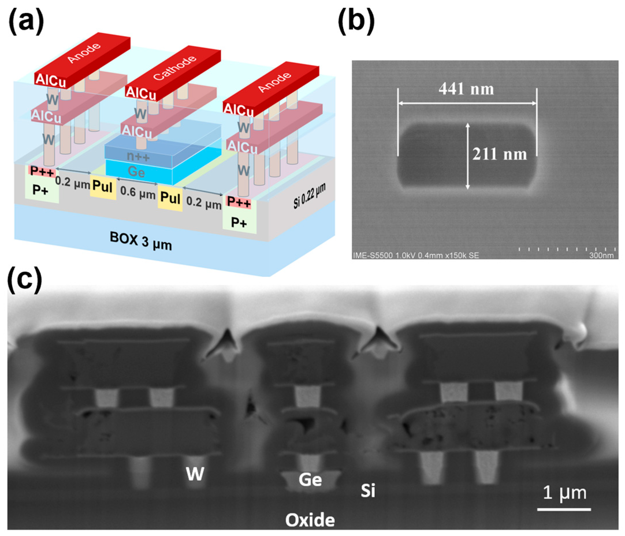
Figure 1. Structure of the waveguide-integrated SACM vertical Ge/Si APD. (a) Three-dimensional structure diagram of the Ge on Si avalanche photodetector. (b) Cross-section SEM image of the waveguide core. (c) FIB cross-sectional view of the device.
Photonics 10 00750 g001
Figure 2. The key process for the waveguide-integrated SACM vertical Ge/Si APD. (a) Fabrication of the channel waveguide with 220 nm etching and grating with 70 nm etching on the top Si. (b) Implantation of the charge layer and P-type implantation for ohmic contact. (c) Selective epitaxial growth of germanium and N-type implantation on the germanium layer for ohmic contact. (d) The first and second metal deposition, patterning, and device passivation.
Photonics 10 00750 g002
Figure 3. (a,b) Topography SEM image of the hole in the germanium layer seen in Figure 2c. (c,d) Topography SEM image of the hole after the first metal, before W deposition.
Photonics 10 00750 g003
Figure 4. (a) The measured dark current and photocurrent I–V curves with different input optical powers. (b) The measured responsivity with different input optical powers.
Photonics 10 00750 g004
Figure 5. The measured multiplication gain at different bias voltages as the input power varied.
Photonics 10 00750 g005
Figure 6. Experimental setup for characterizing the present waveguide Ge/Si APD. The red and blue lines represent the optical and electrical connections, respectively. (a) Dark current test, (b) photocurrent test, and (c) O-E bandwidth test. LCA, light-wave component analyzer; PC, polarization controller; RF, radiofrequency; DC, direct current. (d) Eye diagram test. LN MZM, lithium niobate Mach-Zehnder modulator; AWG, arbitrary waveform generator.
Photonics 10 00750 g006
Figure 7. (a) The measured frequency responses under different bias voltages, varying from 12 V to 15.7 V. (b) The measured frequency responses under 15.7 V.
Photonics 10 00750 g007
Figure 8. (a) The extracted 3 dB bandwidth is the function of the reverse voltage. (b) The extracted gain bandwidth product is the function of the reverse voltage.
Photonics 10 00750 g008
Figure 9. Measurement of eye diagrams for receiving the 28 Gbps data. Here, the wavelength was 1310 nm, BR = 28 Gbps, V b i a s = −16 V, and P i n = −9 dBm.
Photonics 10 00750 g009
Table 1. Summary of the reported waveguide Ge/Si APDs.
Ref.Device Typeλ
(nm)
Vbias
(V)
Idark
(µA)
R0
(A/W)
3 dB BW
(GHz)
GBP
(GHz)
[6]Lateral RT1310141000.9348615
[9]Lateral SAM155010.631.90.820.7217
[10]Lateral p(Ge)-i(Ge)-n(Si)1550116000.4933210
[11]Lateral p-i-n-Ge155076100.411190
[16]Lateral SACM131010300.6522.7238
[21]Vertical SACM-p(Ge)15506.410000.4818.9284
[40]Vertical SACM-n(Ge)15508.5370.818.2182
[41]Vertical SACM-p(Ge)1310180.270.636360
[42]Vertical SACM-p(Ge)1550311000.86.24432
This workVertical SACM-n(Ge)131015.74500.6825.7247
Disclaimer/Publisher’s Note: The statements, opinions and data contained in all publications are solely those of the individual author(s) and contributor(s) and not of MDPI and/or the editor(s). MDPI and/or the editor(s) disclaim responsibility for any injury to people or property resulting from any ideas, methods, instructions or products referred to in the content.