Abstract
In order to reduce the number of devices in and cost of a multifrequency vector millimeter-wave (mm-wave) signal generation system, we propose a novel scheme for multifrequency vector mm-wave signal generation based on one dual-arm Mach-Zehnder modulator (MZM) without optical filtering. This scheme utilizes the carrier suppression modulation of a single modulator, without the need for optical filtering and combines precoding technology to generate high-frequency QPSK and 16 QAM mm-wave signals. The transmitter is applied with precoding technology to make the frequency multiplying vector mm-wave signal display regular vector modulation at the receiver, and the system is optimized with a phase factor to ensure that the phase distribution of QPSK signal at the receiver is symmetrical. We demonstrated the generation of 4-Gbaud 76 GHz QPSK and 16 QAM vector mm-wave signals through simulation. The simulation results show that, at a fiber transmission distance of 12 km, when the launched optical power of the PD is greater than −20.535 dBm, the bit error ratio (BER) of the QPSK signal is lower than the hard-decision forward error correction (HD-FEC) threshold of 3.8 × 10⁻³. At a fiber transmission distance of 10 km, when the launched optical power of the PD is greater than −18.637 dBm, the BER of 16 QAM signal is also lower than 3.8 × 10⁻³.
1. Introduction
The quality and cost of mm-wave signals directly determine the performance of optical mm-wave communication systems and also affect whether they can be implemented for commercial use. Therefore, in recent years, how low-frequency RF signals can be used to achieve efficient and low-cost mm-wave signals has become a research hotspot. The photon-assisted mm-wave generation method features high frequency and large bandwidth, which can effectively overcome the impact of electronic bottlenecks and generate high-frequency signals with low-frequency RF source signals [1,2,3,4,5].
At present, the main methods for generating optical mm-waves are based on the direct modulator, remote heterodyning, the external intensity modulator, four-wave mixing (FWM), and Brillouin scattering [6,7,8,9,10]. Among them, the method of using the external intensity modulator based on the principle of frequency multiplication to generate mm-waves of frequency multiplication light, which features high stability and low cost, is a hot research topic at home and abroad [10,11,12,13,14,15,16]. In one study [11], an arbitrary frequency multiplying signal was generated based on a single MZM and an optical wavelength selection switches (WSS) scheme. Experimental demonstrations were conducted to demonstrate the generation of a 96 GHz vector mm-wave signal using precoded RF carrying 4-Gbaud QPSK signal at 12 GHz. However, due to bandwidth limitations, filters severely restrict the adjustable range of the system, while increasing its complexity and cost. Furthermore, many researchers have turned their attention to mm-wave generation without WSS. In another study [12], the generation of multifrequency signals such as 40 GHz, 80 GHz, and 120 GHz was achieved using two MZMs in parallel without the use of optical filters. However, in this scheme, the generation of mm-wave signal requires the use of two or more MZMs in cascade or parallel to achieve this; the precise synchronization of each modulator is also required, making the vector mm-wave signal generation system more complex and requiring higher costs. Li et al. [13] proposed a new, simple scheme to generate the frequency quadrupling signal using only a single drive MZM, without the need for an optical filter. The generation of a 40 GHz QPSK signal has been proven in experiments, which have demonstrated that the signal can carry 1-Gbaud QPSK data with a BER of less than 3.8 × 10⁻³. At the same time, in order to solve the phase multiplication caused by frequency multiplication, the RF signal is precoded with a signal phase of 1/2 of the conventional phase. However, the generation of a high-order 16 QAM modulation mm-wave signal requires more complex amplitude precoding techniques, which have not been analyzed or simulated. Li et al. [14] also studied MZM-based OCS modulation and precoding techniques to achieve vector signal generation. Their experimental results demonstrated the successful generation of 1-Gbaud vector signals, which were modulated using QPSK and operated at a frequency of 12 GHz. However, the scheme was only studied as a double frequency system, and the signal rate was small, while the frequency of the generated signal was very small. Lu et al. [16] theoretically proposed an optical mm-wave generation scheme based on frequency quadrupling and sextupling techniques. The scheme employs a single electrode modulator and is capable of filtering out the center carrier by adjusting the modulation index. However, the undesired sidebands still required filtering, and the system’s BER and performance were not analyzed. Further experimental or simulation studies are necessary to verify the proposed scheme. In addition, due to the limited bandwidth of the digital-to-analog converter, the mm-wave signal is affected by filtering, and the points of the unbalanced distribution constellation become narrower and longer, causing some points of the constellation to stick to each other. Additionally, due to the limited effective number of bits in the digital-to-analog converter, when the signal-to-noise ratio is small, the points of the constellation become close to each other, leading to error codes.
In this study, we used a dual-arm MZM to generate mm-wave signals, avoiding the use of filtering devices, which greatly reduced system costs and improved the tunability and system stability of the entire mm-wave band. The generated carrier suppression vector mm-wave signal was beat at the PD end to directly obtain double- and quadruple-frequency mm-waves, achieving the goal of increasing mm-wave frequency. Compared to the single-arm MZM, which experiences the chirping phenomenon and affects long-distance transmission, this study adopted a dual-arm MZM, which can achieve zero chirp. At the same time, the 16 QAM modulation format was applied to improve the system transmission capacity. Precoding and phase factor optimization techniques were used to better demodulate the distortion generated during signal transmission and to optimize the system to reduce the error codes. Through simulation, it is verified that the generated 4-Gbaud QPSK signal, by quadrupling the 19 GHz RF signal, and the generated 4-Gbaud 16 QAM signal, by doubling the 38 GHz RF signal, can realize 12 km and 10 km fiber transmission with a BER of less than 3.8 × 10⁻³, respectively.
2. Principle of Photonic Multifrequency Vector Mm-Wave Signal Generation
Figure 1 shows a schematic diagram of the photonic multifrequency vector mm-wave signal scheme generated using a single dual-arm MZM. As shown in Figure 1a, 16 QAM or QPSK modulation format precoded vector signals with frequency fs are realized by the MATLAB program. First, the pseudo-random binary sequence (PRBS) is vector mapped, then it is phase precoded and amplitude precoded, which is followed by the application of a low-pass filter, and finally, the vector signal is upconverted to the RF domain through cosine and sine functions, whose frequency is fs.
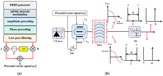
Figure 1.
Schematic diagram of photonic multifrequency vector mm-wave signal generation. (a) Generation procedure of QPSK/16 QAM modulated precoded vector signal at fs; (b) schematic diagram of the output spectrum of MZM.
As shown in Figure 1b, the scheme omits the filter in the dashed box and generates only two symmetric-order subcarriers by adjusting the MZM to operate at the maximum or minimum transmission point, without filtering out the excess sidebands. The output frequency of the continuous wave (CW) laser is fc, and the continuous light wave is modulated by a precoded vector signal with a frequency of fs. The dc bias of a dual-arm modulator is set at the maximum transmission point or the minimum transmission point, and the multifrequency signal is obtained after the PD beating. It is assumed that the signals at frequency fs of the drive RF and frequency fs of the CW laser are expressed as:
where E0 is a constant, representing the amplitude of continuous wave output. K and φ represent the amplitude and phase of the driving RF signal, respectively. When the sender’s data are in a multi-amplitude vector modulation format, such as 8 QAM and 16 QAM, K can have several different values. Vdrive represents the driving voltage.
The CW laser is modulated by the precoded vector signal of MZM, and the output signal can be expressed as
where , which represents the initial phase caused by DC bias voltage, and , which represents the modulation depth of the MZM.
- (1)
- When the MZM works in Negative mode and is biased at its minimum transmission point, , which is , and
It can be seen from Equation (4) that the even-order carrier sideband, including the center carrier, is suppressed in the optical signal, while the odd-order carrier sideband is retained.
Figure 2a plots the values of J1, J3, J5, and J7 against m. J1, J3, J5, and J7 continue to increase with the increase in m. As m increases to one, J5 and J7 decrease to zero, while J1 and J3 increase to 0.4401 and 0.0196, respectively. Therefore, the odd-order photonic carrier with an order greater than one can be ignored, and the error is not significant. Additionally, the discrete spectrum of the MZM output signal has two subcarriers of ±1 order with high power. As shown in Figure 1b, the expression of MZM output signal can be given as
where J1 is the first-order Bessel function of the first class.
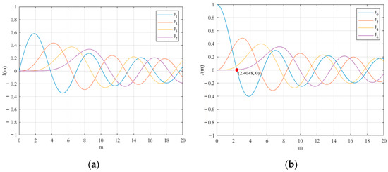
Figure 2.
The first-kind Bessel function curve. (a) The function curve of the first order, third order, fifth order, and seventh order; (b) the function curve of the zeroth order, second order, fourth order, and sixth order.
Then, the output signal of MZM is sent to the PD detector for heterodyne beating, and the RF signal can be represented as
where R represents the PD sensitivity. As can be seen, we obtain a 16 QAM signal whose frequency is 2 fs.
Based on this scheme, we achieve photonic multifrequency, which upconvert low-frequency vector signals into high-frequency signals by using low bandwidth electro-optic components at the transmitting end, and the phase of the 16 QAM modulation signal at the receiving end is twice that of the vector signal at the transmitting end. Thus, phase precoding is required for the driving signal. In order to ensure the 16 QAM modulation of the vector mm-wave signal obtained after PD detection, amplitude precoding of the driving RF signal is also needed. The mode of even carrier sideband suppression is used, and positive and negative first-order sideband beats are selected, so the phase precoding formula and amplitude precoding formula of 16 QAM are as follows:
where and represent the amplitude and phase of the regular 16 QAM signal constellation points, respectively; and , respectively represent the amplitude and phase of the 16 QAM signal constellation point after precoding; and is the first kind of the inverse function of the first-order Bessel function.
- (2)
- When the MZM works in Negative mode and is biased at its maximum transmission point, VDC = 0, which is γ = 0, and
It can be seen from Equation (9) that the even-order carrier sideband, including the center carrier, is retained in the optical signal, while the odd-order carrier sideband is suppressed. Therefore, for the realization of quadrupling the frequency, it is necessary to remove the center carrier and other higher-order carriers and then beat the frequency of positive and negative second-order subcarriers.
Figure 2b shows the curves of J0, J2, J4, and J6 as they relate to m. It can be seen that J0 decreases when m increases, while J2, J4, and J6 continue to increase when m increases. As m increases to 2.4048, J0 decreases to zero, while J2, J4, and J6 increase to 0.4318, 0.0647, and 0.0034, respectively. In other words, when we properly adjust the driving voltage of the MZM to ensure that m is approximately equal to 2.4048—that is, biased at its maximum transmission point—the central photonic carrier can be effectively suppressed, and the even-order photonic carriers larger than second order can be neglected with little error. Therefore, the discrete spectrum of the MZM output signal has two subcarriers of ±2 order with high power. As shown in Figure 1b, the MZM output signal can be expressed as
where J2 is the second-order Bessel function of the first class, , and and represent the driving voltage and half-wave voltage of MZM, respectively. Then, the output signal of MZM is sent to the PD for heterodyne beating, and the RF signal can be represented as
where R represents PD sensitivity. As can be seen, we obtain a QPSK signal whose frequency is 4 fs.
Based on the aforementioned findings, we can achieve photonic quadruple frequency conversion. Specifically, the low-frequency vector signal is upconverted to a high-frequency signal at the transmitter using low-bandwidth electro-optical components. Meanwhile, at the receiver end, the phase of the QPSK-modulated signal is quadrupled by the heterodyne beating. Consequently, it is necessary to implement phase precoding of the drive signal.
Because the amplitudes of the QPSK constellation points are the same and the position signals are transformed the same way by MZM and PD, it is not necessary to carry out amplitude precoding, as it would be in the case of other high-order QAM modulation techniques, but only phase precoding. In this scheme, positive and negative second-order sideband beats are selected, so the phase precoding formula of QPSK is expressed as
where and represent the phase of the standard and the QPSK signals after precoding.
In the QPSK mm-wave generation system, as the signal rate and RF signal frequency increase, the system operation is constrained by the bandwidth of the digital-to-analog converter. As a result, the QPSK constellation points can exhibit phase deviation, which can lead to transmission errors in the system. We propose a method to address the issue of imbalanced phase distribution of the received signal caused by bandwidth constraints in the QPSK modulation process. By optimizing the phase factor of the precoding vector signal at the transmitter, the recovered vector signal is symmetrical in phase distribution, thereby improving system performance.
A schematic diagram detailing the process of generating electric RF vector signals based on phase factor optimization on the offline end is shown in Figure 3, and the optimization of the phase factor occurs after the QPSK modulation formatting. The specific formula for phase precoding of QPSK signals during the precoding process is as follows:
where θ represents the phase factor, which is a fixed value with a constant size of four in the QPSK precoded quadrupling frequency system.
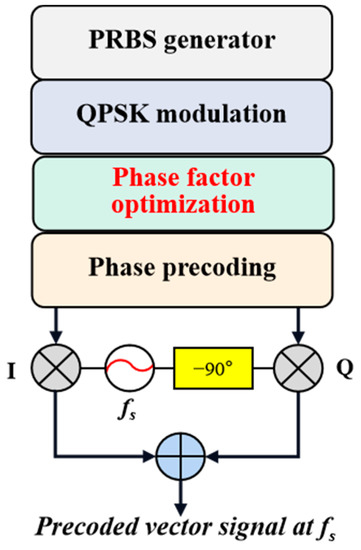
Figure 3.
Schematic diagram of precoding based on phase factor optimization for generating electric RF vector signals.
Since the system uses positive and negative first-order sideband beat frequencies to double the frequency of the RF, the equation θ should be four. In order to make the recovered vector signal at the receiver symmetrical in phase distribution, the phase coding scheme is changed as follows:
It can be seen that the phase distance between the vector constellation points is π/8 when the phase factor is four. When the phase factor is 3.8, the phase distance between the vector constellation points increases to π/7.6. In the phase factor optimization system, the size of θ can be flexibly adjusted according to the limited bandwidth of the digital-to-analog converter. It can make the recovered vector signal at the receiver symmetrical in phase distribution by changing the phase distribution distance. This optimization method can greatly reduce the BER of the system without increasing the complexity of the algorithm or the structure.
3. Simulation Results and Analysis
To verify the correctness of the theoretical analysis, optical communication simulation software VPItransmissionMaker was used to build a simulation system to generate multifrequency vector mm-wave signals using a dual-arm MZM, as shown in Figure 4. In the diagram, CW laser is a continuous wave laser, MZM is the Mahzender modulator, VOA is an optical variable attenuator, Fiber is the single-mode fiber, and PD is a photodetector.
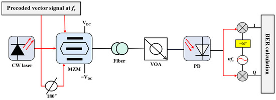
Figure 4.
Simulation diagram of the frequency vector mm-wave signal generated using a dual-arm MZM.
3.1. The Generation of a Double-Frequency 16 QAM Mm-Wave Signal
The scheme was intended to generate a PRBS with a symbol length of 212 and map it to 16 QAM at the MATLAB end with a frequency of fs. In small-signal mode, the DC voltage bias and driving voltage were changed—that is, MZM worked at the maximum bias point—then positive and negative first-order sidebands could be obtained. Next, the MZM output signal generated a 16 QAM vector mm-wave signal by beating the frequency in a PD detector, obtaining the corresponding double-frequency signal. Before the signal entered the PD, a VOA was utilized to control the received signal optical power. Finally, the BER was calculated offline using MATLAB software 2016b.
In the simulation, we used a CW laser with a center frequency of 193.1 THz and a power of 10 dBm. The extinction ratio was 35 dB, the RF was 38 GHz, the amplitude was 1 V, and the responsivity of the PD was 1.0. The continuous light waves emitted by the outer cavity laser are modulated by a pre-coded vector RF signal via MZM, with the vector RF signal having a frequency of 38 GHz and carrying a 4-Gbaud 16 QAM signal. The MZM had a half-wave voltage of 5 V, a bias voltage difference of 5 V, and a drive voltage of 1 V. At the receiver, the MZM output was transmitted over a fiber link with a length of 10 km and a dispersion of 16 ps/km/nm at 1550 nm with no optical dispersion compensation.
Constellation diagrams from before and after 16 QAM precoding are shown in Figure 5. Figure 5a represents a standard 16 QAM constellation diagram, and Figure 5b represents the constellation diagram after double-frequency 16 QAM precoding.
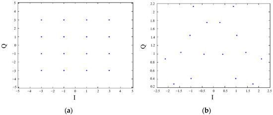
Figure 5.
16 QAM constellation diagram. (a) 16 QAM constellation diagram before precoding; (b) 16 QAM constellation diagram after precoding.
Figure 6a shows the transmitter spectrum. At the transmitting end, the PRBS was mapped as 16 QAM, and the vector RF signal frequency was 38 GHz. Through the modulation of MZM, the positive and negative first-order sideband 38 GHz optical signals were produced, and their spectral diagram is shown in Figure 6b.

Figure 6.
The signal spectrum. (a) The transmitter spectrum of 38 GHz; (b) the output signal spectrum of MZM.
At the receiver, the signal passed through a fiber optic link. After the VOA, the PD obtained the 16 QAM mm-wave electrical signal with a 76 GHz frequency by doubling the beat frequency. Finally, the original data was obtained by IQ down-conversion using digital processing technology.
The spectrogram and electrogram were obtained using VPI simulation, and the simulation verified the correctness of the theoretical analysis. In order to observe the data more clearly, the Origin data processing software was used to process the simulated data in VPI. The processing results are shown in Figure 7. The BER was used to evaluate the performance of the received signal, and the error probability is described by the number of error bits per unit time. We can see that with the gradual increase in launched power, the BER becomes smaller and smaller; that is, the BER performance improves with an increase in launched power.
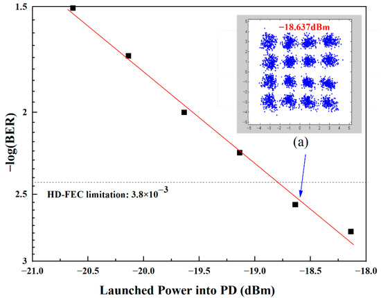
Figure 7.
The BER performance varies with the launched power. (a) The recovered 16 QAM constellation.
To obtain the simulation results, the generated 4-Gbaud 76 GHz 16 QAM vector signal was transmitted through 10 km of optical fiber. When the launched power is greater than −18.637 dBm, its BER is less than 3.8 × 10⁻³. When the launched power value is −18.637 dBm, its corresponding recovery constellation is shown in Figure 7a with good performance.
3.2. The Generation of Quadruple-Frequency QPSK Mm-Wave Signal
The scheme was intended to generate a PRBS with a symbol length of 212 and map it to QPSK at the MATLAB end with a frequency of fs. In small-signal mode, the DC voltage bias and driving voltage were changed—that is, MZM worked at the minimum bias point—and positive and negative second-order sidebands could be obtained. Next, the MZM output signal generated a 4 QPSK vector mm-wave signal by beating the frequency in a PD detector, obtaining the corresponding quadrupling frequency signal. Before the signal entered the PD, a VOA was utilized to control the received signal optical power. Finally, the BER was calculated offline using MATLAB software 2016b.
In the simulation, we used a CW laser with a center frequency of 193.1 THz and a power of 10 dBm. The power was 10 dBm, the extinction ratio was 35 dB, the RF was 19 GHz, the amplitude was 1 V, and the responsivity of the PD was one. The continuous light waves emitted by the outer cavity laser are modulated by a pre-coded vector RF signal via MZM, with the vector RF signal having a frequency of 19 GHz and carrying a 4-Gbaud QPSK signal. The MZM had a half-wave voltage of 5 V, a bias voltage difference of 0 V, and a drive voltage of 3.827 V. Subsequently, the output signal from the MZM was transmitted over a 12 km fiber link, with a dispersion parameter of 16 ps/km/nm at a wavelength of 1550 nm, and without any form of optical dispersion compensation.
Constellation diagrams from before and after QPSK precoding are shown in Figure 8. Figure 8a represents a standard QPSK constellation diagram, and Figure 8b represents the constellation diagram after the quadruple-frequency precoding of standard QPSK.
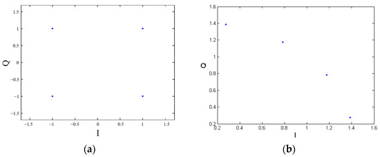
Figure 8.
QPSK constellation diagram. (a) QPSK constellation diagram before precoding; (b) QPSK constellation diagram after precoding.
Figure 9a shows the transmitter spectrum. At the transmitting end, the PRBS was mapped as QPSK, and the vector RF was 19 GHz. Through the modulation of MZM, positive and negative second-order sideband 38 GHz signals were produced, and their spectral diagram is shown in Figure 9b. At the receiver, the signal passed through a fiber optic link, and after the VOA, the QPSK mm-wave electrical signal with a 76 GHz frequency was obtained by quadrupling the beat frequency of the PD.

Figure 9.
The signal spectrum. (a) The transmitter spectrum of 19 GHz; (b) the output signal spectrum of MZM.
The spectrogram and electrogram were obtained by VPI simulation, and the simulation verified the correctness of the theoretical analysis, as shown in Figure 10. We can see that with the gradual increase in launched power, the BER becomes smaller and smaller; that is, the BER performance improves with an increase in launched power.
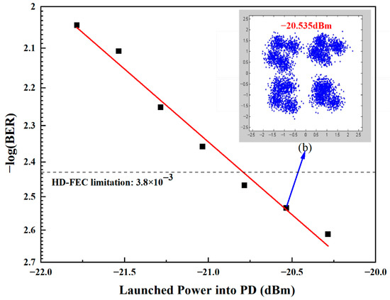
Figure 10.
The BER performance varies with the launched power. (b) The recovered QPSK constellation.
For simulation testing, the generated 4-Gbaud 76 GHz QPSK vector signal was transmitted through optical fiber for 12 km. When the launched power is greater than −20.535 dBm, its BER is less than 3.8 × 10⁻³. When the launched optical power is −20.535 dBm, its corresponding recovery constellation is shown in Figure 10b with good performance.
Below, we demonstrate the feasibility of a phase factor optimization system under QPSK modulation by generating a 76 GHz mm-wave signal carrying an 8-GBaud QPSK signal as an example. Based on the theoretical analysis presented above, it is evident that the QPSK quadruple vector signal generated by the system requires phase precoding. Furthermore, the phase factor of the precoded signal must be optimized, with a target phase factor of four for the quadrupled signal. This is because the phase of the precoded signal should be one quarter of that of the standard QPSK signal.
We observed the signal constellation by changing the value of the phase factor. When the phase factor changes from 3.6 to 4.1, the resulting constellation is shown in Figure 11. The input power of the PD was −15.803 dBm. From Figure 11e, it can be seen that there is phase asymmetry in the constellation, and the constellation points are phase shifted, which increases the BER of system. It can be seen that, compared to other phase factors, when the phase factor is adjusted to 3.8, the phase of the constellation points is uniformly and symmetrically distributed.
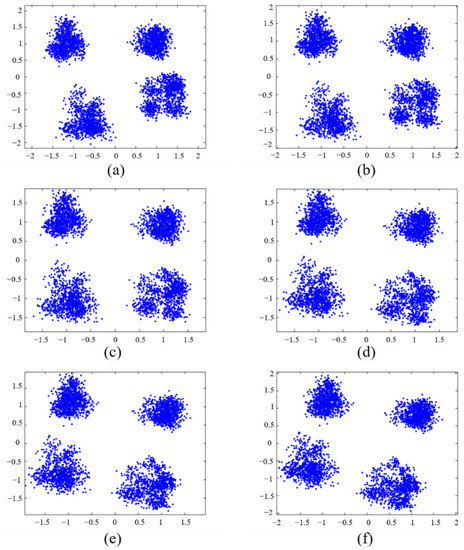
Figure 11.
Constellations of an 8-Gbaud QPSK signal at 76 GHz with an input power of −15.803 dBm into the PD with phase factor. (a) 3.6, (b) 3.7, (c) 3.8, (d) 3.9, (e) 4.0, and (f) 4.1.
Figure 12 shows the relationship between the BER and the phase factor obtained by the system when the launched optical power is −15.803 dBm. It can be seen that optimizing the phase factor can greatly improve the BER performance. It is also clear from the figure that the system with a phase factor of 3.8 outperforms the systems with phase factors of 3.7 and 4.0 when a certain received optical power is satisfied. When the phase factor is 3.8, the BER reaches its lowest value of less than 1 × 10⁻⁵.
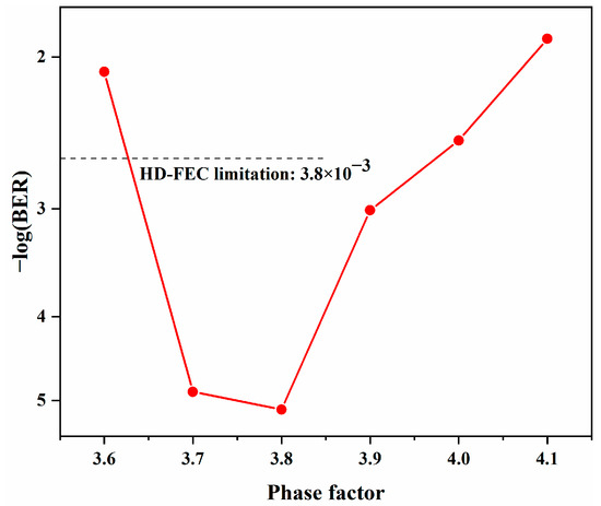
Figure 12.
BER under different phase factor conditions with a launch power of −15.803 dBm.
4. Conclusions
We have proposed a novel scheme for the generation of a photonic multifrequency vector mm-wave signal based on a dual-arm MZM. The scheme is intended to omit the filter and generate QPSK and 16 QAM vector mm-wave signals by changing the operating mode and modulation depth of the MZM and uses precoding techniques, which will save on expensive devices and greatly reduce the system cost. By adopting this approach, we have simulated and demonstrated the generation of 4-Gbaud 76 GHz 16 QAM and QPSK vector mm-wave signals. The optical fiber transmission of 10 and 12 m can be achieved with a BER of less than 3.8 × 10⁻³. Additionally, the system employs a phase factor optimization technique, and after optimizing the phase factor to 3.8, the performance of the 76 GHz mm-wave doubling frequency generation system carrying an 8-GBaud QPSK signal is greatly improved, and the phase of the QPSK constellation points is uniformly and symmetrically distributed.
Author Contributions
Conceptualization, L.C. and Q.Y.; methodology, L.C. and Q.Y.; software, Q.Y.; validation, L.C. and Q.Y.; formal analysis, L.C. and Q.Y.; investigation, L.C. and Q.Y.; resources, L.C.; data curation, Q.Y.; writing—original draft preparation, Q.Y.; writing—review and editing, J.L. All authors have read and agreed to the published version of the manuscript.
Funding
This research was funded by the Scientific Research Fund of Hunan Provincial Education Department, grant number 22B0479; the National Natural Science Foundation of China, grant number 61905074.
Institutional Review Board Statement
Not applicable.
Informed Consent Statement
Not applicable.
Data Availability Statement
Not applicable.
Conflicts of Interest
The authors declare no conflict of interest.
References
- Umezawa, T.; Kanno, A.; Kashima, K.; Matsumoto, A.; Akahane, K.; Yamamoto, N.; Kawanishi, T. Bias-Free Operational UTC-PD above 110 GHz and Its Application to High Baud Rate Fixed-Fiber Communication and W-Band Photonic Wireless Communication. J. Light. Technol. 2016, 34, 3138–3147. [Google Scholar] [CrossRef]
- Li, X.; Xu, Y.; Xiao, J.; Wang, K.; Yu, J. W-band 16QAM-modulated SSB photonic vector Mm-wave signal generation by one single I/Q modulator. In Proceedings of the 2017 Optical Fiber Communications Conference and Exhibition (OFC), Los Angeles, CA, USA, 19–23 March 2017. [Google Scholar]
- Alavi, S.E.; Amiri, I.S.; Khalily, M.; Fisal, N.; Supa’at, A.S.; Ahmad, H.; Idrus, S.M. W-Band OFDM for Radio-over-Fiber Direct-Detection Link Enabled by Frequency Nonupling Optical Up-Conversion. IEEE Photonics J. 2017, 6, 7903908. [Google Scholar] [CrossRef]
- Chen, L.; Luo, J.; Tang, Z.; Xi, Z. Integration system of photon-assisted W-band millimeter wave wireless communication and free space optical communication based on OFDM signal transmission. Opt. Fiber Technol. 2019, 52, 101973. [Google Scholar] [CrossRef]
- Yu, J.; Jia, Z.; Yi, L.; Su, Y.; Chang, G.K.; Wang, T. Optical millimeter-wave generation or up-conversion using external modulators. IEEE Photonics Technol. Lett. 2005, 18, 265–267. [Google Scholar]
- Wang, D.; Xi, L.; Tang, X.; Zhang, X.; Gao, N. A simple photonic precoding-less scheme for vector millimeter-wave signal generation based on a single phase modulator. Results Phys. 2020, 19, 103412. [Google Scholar] [CrossRef]
- Xue, Z.-Z.; Pei, L.; Liu, T.-T.; Xie, Y.-H.; Li, J. Photonic Generation of Filterless Frequency Multiple Tupling Optical Millimeter-wave Signal. Acta Photonica Sin. 2020, 49, 0406002. [Google Scholar]
- Li, X.; Zhang, J.; Xiao, J.; Zhang, Z.; Xu, Y.; Yu, J. W-Band 8QAM Vector Signal Generation by MZM-Based Photonic Frequency Octupling. IEEE Photonics Technol. Lett. 2015, 27, 1257–1260. [Google Scholar] [CrossRef]
- Baskaran, M.; Prabakaran, R. Optical millimeter wave signal generation with frequency 16-tupling using cascaded MZMs and no optical filtering for radio over fiber system. J. Eur. Opt. Soc.-Rapid Publ. 2018, 14, 13. [Google Scholar] [CrossRef]
- Zhao, L.; Xiong, L.; Liao, M.; Xia, J.; Pang, Y.; Shi, X. W-band 8QAM vector millimeter-wave signal generation based on tripling of frequency without phase pre-coding. IEEE Access 2019, 7, 156978–156983. [Google Scholar] [CrossRef]
- Li, X.; Yu, J.; Zhang, Z.; Xiao, J.; Chang, G.K. Photonic vector signal generation at W-band employing an optical frequency octupling scheme enabled by a single MZM. Opt. Commun. 2015, 349, 6–10. [Google Scholar] [CrossRef]
- Zhang, Y.; Liu, B.; Ji, S. Generation of Multiple-Frequency Optical Millimeter-Wave Signal with Optical Carrier Suppression and No Optical Filter. IEEE Photonics J. 2017, 9, 5500607. [Google Scholar] [CrossRef]
- Li, X.; Yu, J.; Chang, G.K. Frequency-quadrupling vector mm-wave signal generation by only one single-drive MZM. IEEE Photonics Technol. Lett. 2016, 28, 1302–1305. [Google Scholar] [CrossRef]
- Li, X.; Yu, J.; Zhang, J.; Xiao, J.; Zhang, Z.; Xu, Y.; Chen, L. QAM vector signal generation by optical carrier suppression and precoding techniques. IEEE Photonics Technol. Lett. 2015, 27, 1977–1980. [Google Scholar] [CrossRef]
- Zhang, L.; Hu, X.; Cao, P.; Zhuang, Z.; Jiang, X.; Su, Y. A flexible multi-16QAM transmitter based on cascaded dual-parallel Mach-Zehnder modulator and phase modulator. Sci. China Technol. Sci. 2013, 56, 598–602. [Google Scholar] [CrossRef]
- Lu, J.; Dong, Z.; Liu, J.; Zeng, X.; Hu, Y.; Gao, J. Generation of a frequency sextupled optical millimeter wave with a suppressed central carrier using one single-electrode modulator. Opt. Fiber Technol. 2014, 20, 533–536. [Google Scholar] [CrossRef]
Disclaimer/Publisher’s Note: The statements, opinions and data contained in all publications are solely those of the individual author(s) and contributor(s) and not of MDPI and/or the editor(s). MDPI and/or the editor(s) disclaim responsibility for any injury to people or property resulting from any ideas, methods, instructions or products referred to in the content. |
© 2023 by the authors. Licensee MDPI, Basel, Switzerland. This article is an open access article distributed under the terms and conditions of the Creative Commons Attribution (CC BY) license (https://creativecommons.org/licenses/by/4.0/).