Broadband Mid-Infrared Frequency Comb in Integrated Chalcogenide Microresonator

Abstract
1. Introduction
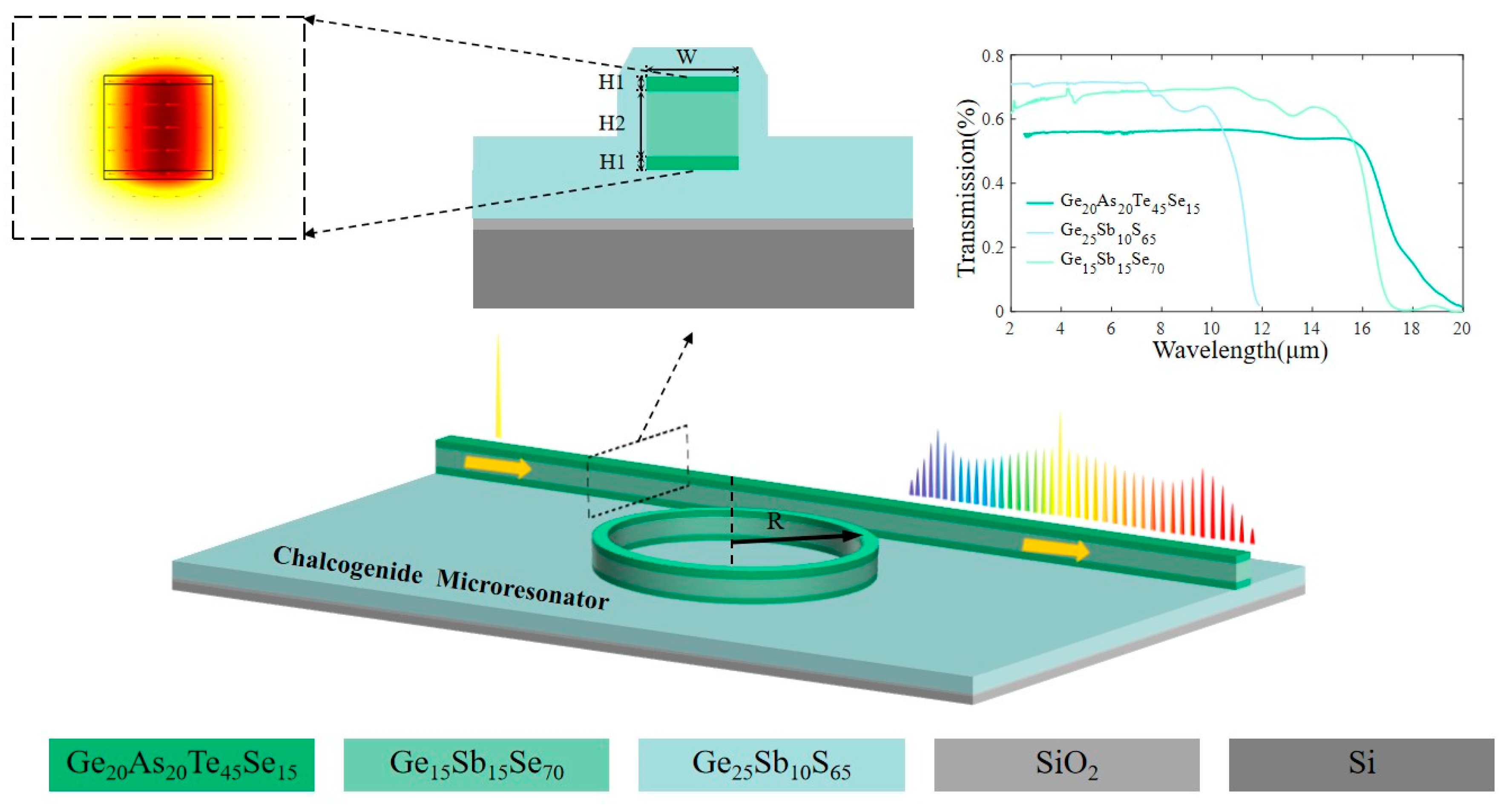
2. Design Principle
3. Results and Discussion
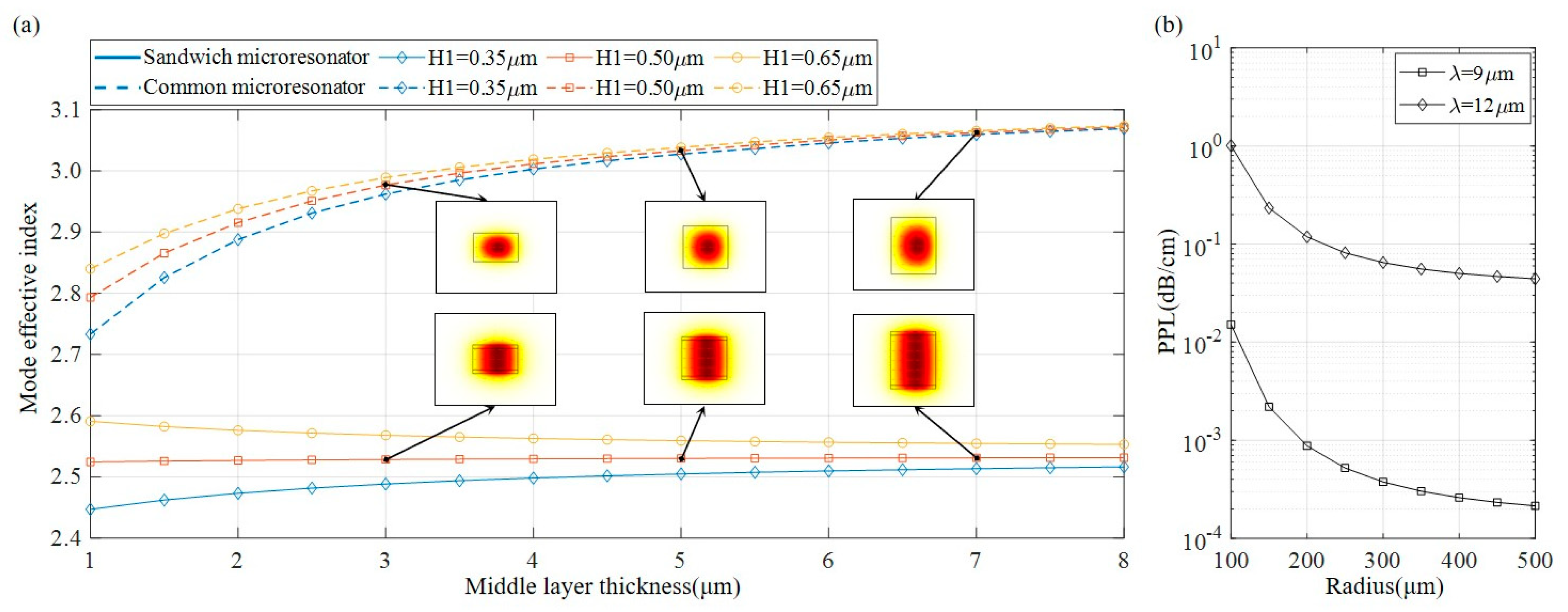
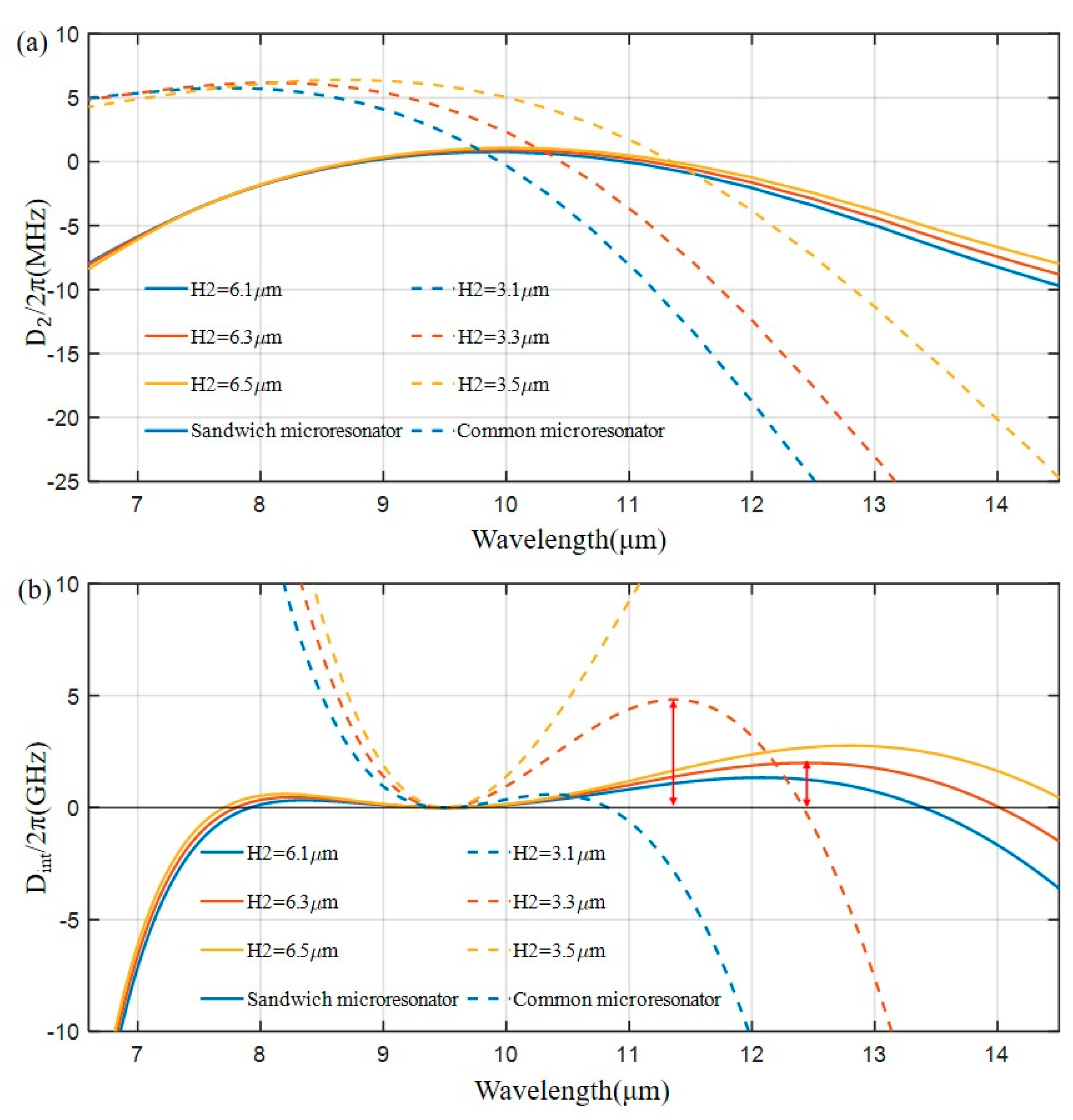
3.1. Dispersion Engineering
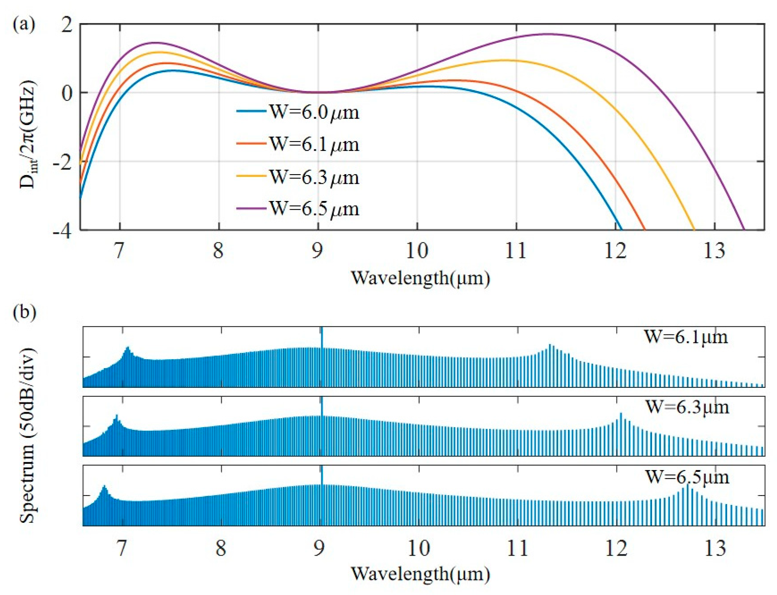
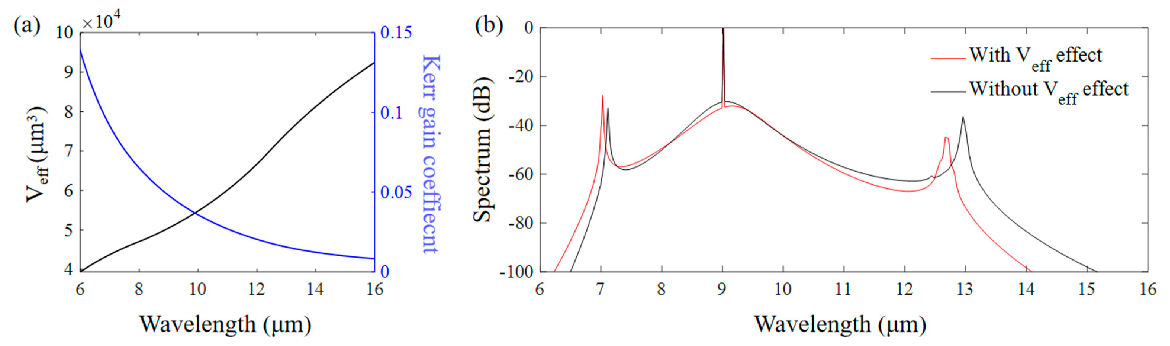
3.2. Generation of MIR Micro comb
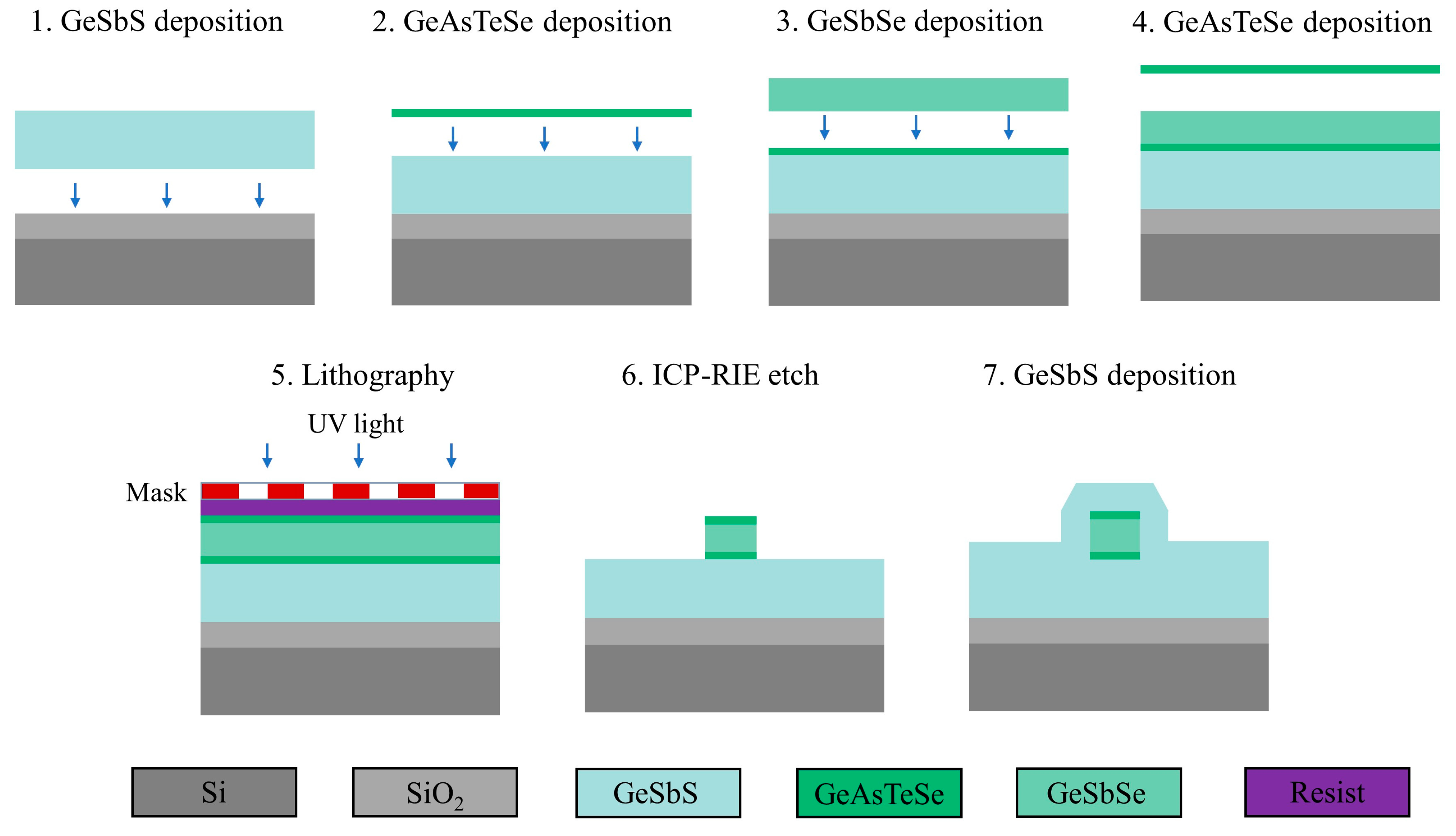
3.3. Schematic of Fabrication Procedures
4. Conclusions
Author Contributions
Funding
Institutional Review Board Statement
Informed Consent Statement
Data Availability Statement
Conflicts of Interest
References
- Luke, K.; Okawachi, Y.; Lamont, M.R.; Gaeta, A.L.; Lipson, M. Broadband Mid-Infrared Frequency Comb Generation in a Si(3)N(4) Microresonator. Opt. Lett. 2015, 40, 4823–4826. [Google Scholar] [CrossRef] [PubMed]
- Schliesser, A.; Picqué, N.; Hänsch, T.W. Mid-Infrared Frequency Combs. Nat. Photonics 2012, 6, 440–449. [Google Scholar] [CrossRef]
- Yu, M.; Okawachi, Y.; Griffith, A.G.; Lipson, M.; Gaeta, A.L. Mode-Locked Mid-Infrared Frequency Combs in a Silicon Microresonator. Optica 2016, 3, 854–860. [Google Scholar] [CrossRef]
- Lin, H.; Luo, Z.; Gu, T.; Kimerling, L.C.; Wada, K.; Agarwal, A.; Hu, J. Mid-Infrared Integrated Photonics on Silicon: A Perspective. Nanophotonics 2018, 7, 393–420. [Google Scholar] [CrossRef]
- Petersen, C.R.; Møller, U.; Kubat, I.; Zhou, B.; Dupont, S.; Ramsay, J.; Benson, T.; Sujecki, S.; Abdel-Moneim, N.; Tang, Z. Mid-Infrared Supercontinuum Covering the 1.4–13.3 Μm Molecular Fingerprint Region Using Ultra-High Na Chalcogenide Step-Index Fibre. Nat. Photonics 2014, 8, 830–834. [Google Scholar] [CrossRef]
- Spencer, D.T.; Drake, T.; Briles, T.C.; Stone, J.; Sinclair, L.C.; Fredrick, C.; Li, Q.; Westly, D.; Ilic, B.R.; Bluestone, A. An Optical-Frequency Synthesizer Using Integrated Photonics. Nature 2018, 557, 81–85. [Google Scholar] [CrossRef]
- Suh, M.-G.; Yi, X.; Lai, Y.-H.; Leifer, S.; Grudinin, I.S.; Vasisht, G.; Martin, E.C.; Fitzgerald, M.P.; Doppmann, G.; Wang, J. Searching for Exoplanets Using a Microresonator Astrocomb. Nat. Photonics 2019, 13, 25–30. [Google Scholar] [CrossRef] [PubMed]
- Scalari, G.; Faist, J.; Picqué, N. On-Chip Mid-Infrared and Thz Frequency Combs for Spectroscopy. Appl. Phys. Lett. 2019, 114, 150401. [Google Scholar] [CrossRef]
- Jørgensen, A.A.; Kong, D.; Henriksen, M.R.; Klejs, F.; Ye, Z.; Helgason, Ò.B.; Hansen, H.E.; Hu, H.; Yankov, M.; Forchhammer, S.; et al. Petabit-Per-Second Data Transmission Using a Chip-Scale Micro comb Ring Resonator Source. Nat. Photonics 2022, 16, 798–802. [Google Scholar] [CrossRef]
- Marin-Palomo, P.; Kemal, J.N.; Karpov, M.; Kordts, A.; Pfeifle, J.; Pfeiffer, M.H.; Trocha, P.; Wolf, S.; Brasch, V.; Anderson, M.H. Microresonator-Based Solitons for Massively Parallel Coherent Optical Communications. Nature 2017, 546, 274–279. [Google Scholar] [CrossRef] [PubMed]
- Liu, J.; Lucas, E.; Raja, A.S.; He, J.; Riemensberger, J.; Wang, R.N.; Karpov, M.; Guo, H.; Bouchand, R.; Kippenberg, T.J. Photonic Microwave Generation in the X-and K-Band Using Integrated Soliton Micro combs. Nat. Photonics 2020, 14, 486–491. [Google Scholar] [CrossRef]
- Tian, H.; Liu, J.; Dong, B.; Skehan, J.C.; Zervas, M.; Kippenberg, T.J.; Bhave, S.A. Hybrid Integrated Photonics Using Bulk Acoustic Resonators. Nat. Commun. 2020, 11, 3073. [Google Scholar] [CrossRef] [PubMed]
- Hu, J.; He, J.; Liu, J.; Raja, A.S.; Karpov, M.; Lukashchuk, A.; Kippenberg, T.J.; Brès, C.-S. Reconfigurable Radiofrequency Filters Based on Versatile Soliton Micro combs. Nat. Commun. 2020, 11, 4377. [Google Scholar] [CrossRef] [PubMed]
- Karpov, M.; Pfeiffer, M.H.P.; Liu, J.; Lukashchuk, A.; Kippenberg, T.J. Photonic chip-based soliton frequency combs covering the biological imaging window. Nat. Commun. 2018, 9, 1146. [Google Scholar] [CrossRef]
- Kippenberg, T.J.; Gaeta, A.L.; Lipson, M.; Gorodetsky, M.L. Dissipative Kerr Solitons in Optical Microresonators. Science 2018, 361, eaan8083. [Google Scholar] [CrossRef]
- Xia, D.; Huang, Y.; Zhang, B.; Yang, Z.; Zeng, P.; Shang, H.; Cheng, H.; Liu, L.; Zhang, M.; Zhu, Y.; et al. On-Chip Broadband Mid-Infrared Supercontinuum Generation Based on Highly Nonlinear Chalcogenide Glass Waveguides. Front. Phys. 2021, 9, 598091. [Google Scholar] [CrossRef]
- Yu, Y.; Gai, X.; Ma, P.; Choi, D.-Y.; Yang, Z.; Wang, R.; Debbarma, S.; Madden, S.J.; Luther-Davies, B. A Broadband, Quasi-Continuous, Mid-Infrared Supercontinuum Generated in a Chalcogenide Glass Waveguide. Laser Photonics Rev. 2014, 8, 792–798. [Google Scholar] [CrossRef]
- Lin, H.; Song, Y.; Huang, Y.; Kita, D.; Deckoff-Jones, S.; Wang, K.; Li, L.; Li, J.; Zheng, H.; Luo, Z.; et al. Chalcogenide Glass-on-Graphene Photonics. Nat. Photonics 2017, 11, 798–805. [Google Scholar] [CrossRef]
- Li, Z.; Du, Q.; Wang, C.; Zou, J.; Du, T.; Richardson, K.A.; Cai, Z.; Hu, J.; Luo, Z. Externally Pumped Photonic Chip-Based Ultrafast Raman Soliton Source. Laser Photonics Rev. 2021, 15, 2000301. [Google Scholar] [CrossRef]
- Miller, S.A.; Yu, M.; Ji, X.; Griffith, A.G.; Cardenas, J.; Gaeta, A.L.; Lipson, M. Low-Loss Silicon Platform for Broadband Mid-Infrared Photonics. Optica 2017, 4, 707–712. [Google Scholar] [CrossRef]
- Yu, Y.; Gai, X.; Ma, P.; Vu, K.; Yang, Z.; Wang, R.; Choi, D.-Y.; Madden, S.; Luther-Davies, B. Experimental Demonstration of Linearly Polarized 2–10 Μm Supercontinuum Generation in a Chalcogenide Rib Waveguide. Opt. Lett. 2016, 41, 958–961. [Google Scholar] [CrossRef] [PubMed]
- Rodrigues, J.R.; Bhatt, G.R.; Datta, I.; Dave, U.D.; Chaitanya, S.; Shim, E.; Lipson, M. Sin-Based Waveguides with Ultra-Low Thermo-Optic Effect. In Proceedings of the 2022 Conference on Lasers and Electro-Optics (CLEO), San Jose, CA, USA, 15–20 May 2022; p. SM4G-3. [Google Scholar]
- Wang, J.; Guo, Y.; Liu, H.; Kimerling, L.C.; Michel, J.; Agarwal, A.M.; Li, G.; Zhang, L. Robust Cavity Soliton Formation with Hybrid Dispersion. Photonics Res. 2018, 6, 647–651. [Google Scholar] [CrossRef]
- Little, B.E.; Laine, J.P.; Haus, H.A. Analytic Theory of Coupling from Tapered Fibers and Half-Blocks into Microsphere Resonators. J. Light. Technol. 1999, 17, 704. [Google Scholar] [CrossRef]
- Pfeiffer, M.H.; Herkommer, C.; Liu, J.; Guo, H.; Karpov, M.; Lucas, E.; Zervas, M.; Kippenberg, T.J. Octave-Spanning Dissipative Kerr Soliton Frequency Combs in Si3N4 Microresonators. Optica 2017, 4, 684–691. [Google Scholar] [CrossRef]
- Cai, L.; Li, J.; Wang, R.; Li, Q. Octave-Spanning Micro comb Generation in 4h-Silicon-Carbide-on-Insulator Photonics Platform. Photonics Res. 2022, 10, 870–876. [Google Scholar] [CrossRef]
- Akhmediev, N.; Karlsson, M. Cherenkov Radiation Emitted by Solitons in Optical Fibers. Phys. Rev. A 1995, 51, 2602. [Google Scholar] [CrossRef]
- Erkintalo, M.; Xu, Y.; Murdoch, S.; Dudley, J.M.; Genty, G. Cascaded Phase Matching and Nonlinear Symmetry Breaking in Fiber Frequency Combs. Phys. Rev. Lett. 2012, 109, 223904. [Google Scholar] [CrossRef]
- Lucas, E.; Lihachev, G.; Bouchand, R.; Pavlov, N.G.; Raja, A.S.; Karpov, M.; Gorodetsky, M.L.; Kippenberg, T.J. Spatial Multiplexing of Soliton Micro combs. Nat. Photonics 2018, 12, 699–705. [Google Scholar] [CrossRef]
- Lyakh, A.; Maulini, R.; Tsekoun, A.; Go, R.; Patel, C.K.N. Multiwatt Long Wavelength Quantum Cascade Lasers Based on High Strain Composition with 70% Injection Efficiency. Opt. Express 2012, 20, 24272–24279. [Google Scholar] [CrossRef]
- Dan, B.; Kirch, J.D.; Colin, B.; Oresick, K.M.; Chris, S.; Honghyuk, K.; Knipfer, B.B.; Ha, R.J.; Don, L.; Tom, E. High-Efficiency, High-Power Mid-Infrared Quantum Cascade Lasers [Invited]. Opt. Mater. Express 2018, 8, 1378–1398. [Google Scholar]
- Zhou, W.; Lu, Q.Y.; Wu, D.H.; Slivken, S.; Razeghi, M. High-Power, Continuous-Wave, Phase-Locked Quantum Cascade Laser Arrays Emitting at 8 M. Opt. Express 2019, 27, 15776–15785. [Google Scholar] [CrossRef] [PubMed]
- Fei, T.; Zhai, S.; Zhang, J.; Zhuo, N.; Liu, J.; Wang, L.; Liu, S.; Jia, Z.; Li, K.; Sun, Y. High Power Λ ~ 8.5 Μm Quantum Cascade Laser Grown by Mocvd Operating Continuous-Wave up to 408 K. J. Semicond. 2021, 42, 112301. [Google Scholar] [CrossRef]
- Mills, A.A.; Gatti, D.; Jiang, J.; Mohr, C.; Marangoni, M. Coherent Phase Lock of a 9 Μm Quantum Cascade Laser to a 2 Μm Thulium Optical Frequency Comb. Opt. Lett. 2012, 37, 4083–4085. [Google Scholar] [CrossRef] [PubMed]
- Revin, D.G.; Hemingway, M.; Wang, Y.; Cockburn, J.W.; Belyanin, A. Active Mode Locking of Quantum Cascade Lasers in an External Ring Cavity. Nat. Commun. 2016, 7, 11440. [Google Scholar] [CrossRef] [PubMed]
- Wang, T.; Gai, X.; Wei, W.; Wang, R.; Yang, Z.; Shen, X.; Madden, S.; Luther-Davies, B. Systematic Z-Scan Measurements of the Third Order Nonlinearity of Chalcogenide Glasses. Opt. Mater. Express 2014, 4, 1011–1022. [Google Scholar] [CrossRef]
- Lugiato, L.A.; Lefever, R. Spatial Dissipative Structures in Passive Optical Systems. Phys. Rev. Lett. 1987, 58, 2209. [Google Scholar] [CrossRef]
- Kovach, A.; Chen, D.; He, J.; Choi, H.; Dogan, A.H.; Ghasemkhani, M.; Taheri, H.; Armani, A.M. Emerging Material Systems for Integrated Optical Kerr Frequency Combs. Adv. Opt. Photonics 2020, 12, 135–222. [Google Scholar] [CrossRef]
- Coen, S.; Randle, H.G.; Sylvestre, T.; Erkintalo, M. Modeling of Octave-Spanning Kerr Frequency Combs Using a Generalized Mean-Field Lugiato–Lefever Model. Opt. Lett. 2013, 38, 37–39. [Google Scholar] [CrossRef]
- Godey, C.; Balakireva, I.V.; Coillet, A.; Chembo, Y.K. Stability Analysis of the Spatiotemporal Lugiato-Lefever Model for Kerr Optical Frequency Combs in the Anomalous and Normal Dispersion Regimes. Phys. Rev. A 2014, 89, 063814. [Google Scholar] [CrossRef]
- Ren, D.; Dong, C.; Addamane, S.J.; Burghoff, D. High-Quality Microresonators in the Longwave Infrared Based on Native Germanium. Nat. Commun. 2022, 13, 5727. [Google Scholar] [CrossRef]
- Herr, T.; Brasch, V.; Jost, J.D.; Wang, C.Y.; Kondratiev, N.M.; Gorodetsky, M.L.; Kippenberg, T.J. Temporal Solitons in Optical Microresonators. Nat. Photonics 2014, 8, 145–152. [Google Scholar] [CrossRef]
- Mussot, A.; Kudlinski, A.; Louvergneaux, E.; Kolobov, M.; Taki, M. Impact of the Third-Order Dispersion on the Modulation Instability Gain of Pulsed Signals. Opt. Lett. 2010, 35, 1194–1196. [Google Scholar] [CrossRef] [PubMed]
- Xia, D.; Yang, Z.; Zeng, P.; Zhang, B.; Wu, J.; Wang, Z.; Zhao, J.; Huang, J.; Luo, L.; Liu, D.; et al. Integrated Chalcogenide Photonics for Microresonator Soliton Combs. Laser Photonics Rev. 2022, 17, 2200219. [Google Scholar] [CrossRef]
- Zhang, B.; Zeng, P.; Yang, Z.; Xia, D.; Zhao, J.; Sun, Y.; Huang, Y.; Song, J.; Pan, J.; Cheng, H.; et al. On-Chip Chalcogenide Microresonators with Low-Threshold Parametric Oscillation. Photonics Res. 2021, 9, 1272–1279. [Google Scholar] [CrossRef]
- Xia, D.; Huang, Y.; Zhang, B.; Zeng, P.; Zhao, J.; Yang, Z.; Sun, S.; Luo, L.; Hu, G.; Liu, D.; et al. Engineered Raman Lasing in Photonic Integrated Chalcogenide Microresonators. Laser Photonics Rev. 2022, 16, 2100443. [Google Scholar] [CrossRef]


| LLE Simulation Parameters | |
|---|---|
| Pump frequency (THz) | 33.31 |
| Nonlinear refractive index n2 (m2/W) | 2.05 × 10⁻¹⁸ |
| Intrinsic quality factor Qi | 2 × 10⁶ |
| External coupling factor Qc | 2 × 10⁶ |
| Effective mode volume Veff (μm3) | 5.05 × 10⁴ |
| Input pump power Pin (mW) | 405 |
| Free spectral range FSR (GHz) | 87.97 |
| Group refractive index ng | 2.7 |
Disclaimer/Publisher’s Note: The statements, opinions and data contained in all publications are solely those of the individual author(s) and contributor(s) and not of MDPI and/or the editor(s). MDPI and/or the editor(s) disclaim responsibility for any injury to people or property resulting from any ideas, methods, instructions or products referred to in the content. |
© 2023 by the authors. Licensee MDPI, Basel, Switzerland. This article is an open access article distributed under the terms and conditions of the Creative Commons Attribution (CC BY) license (https://creativecommons.org/licenses/by/4.0/).
Share and Cite
Lu, S.; Lin, G.; Xia, D.; Wang, Z.; Luo, L.; Li, Z.; Zhang, B. Broadband Mid-Infrared Frequency Comb in Integrated Chalcogenide Microresonator. Photonics 2023, 10, 628. https://doi.org/10.3390/photonics10060628
Lu S, Lin G, Xia D, Wang Z, Luo L, Li Z, Zhang B. Broadband Mid-Infrared Frequency Comb in Integrated Chalcogenide Microresonator. Photonics. 2023; 10(6):628. https://doi.org/10.3390/photonics10060628
Chicago/Turabian StyleLu, Siqi, Guosheng Lin, Di Xia, Zifu Wang, Liyang Luo, Zhaohui Li, and Bin Zhang. 2023. "Broadband Mid-Infrared Frequency Comb in Integrated Chalcogenide Microresonator" Photonics 10, no. 6: 628. https://doi.org/10.3390/photonics10060628
APA StyleLu, S., Lin, G., Xia, D., Wang, Z., Luo, L., Li, Z., & Zhang, B. (2023). Broadband Mid-Infrared Frequency Comb in Integrated Chalcogenide Microresonator. Photonics, 10(6), 628. https://doi.org/10.3390/photonics10060628