Article

Significant Substrate Effects on Electromagnetic Scattering by Particles in the Infrared Atmospheric Window

1
School of Energy and Power Engineering, Shandong University, Jinan 250061, China
2
Optics & Thermal Radiation Research Center, Shandong University, Qingdao 266237, China
*
Author to whom correspondence should be addressed.
Photonics 2023, 10(4), 476; https://doi.org/10.3390/photonics10040476
Submission received: 30 March 2023 / Revised: 16 April 2023 / Accepted: 19 April 2023 / Published: 21 April 2023
(This article belongs to the Section Optical Interaction Science)

Abstract

:
Particle-dispersed coatings emerged as a promising approach to regulate the apparent radiative properties of underlying substrates in various applications, including but not limited to radiative cooling, thermal management, and infrared stealth. However, most research efforts in this field overlooked the dependent scattering mechanisms between the particles and the substrate, which can impact the optical properties of the particles. In this study, we explored the particle-substrate interactions within the atmospheric radiative window of 8–14 µm. Using the T-matrix method, we calculated the scattering and absorption efficiencies of a dielectric/metallic particle situated above a metallic/dielectric substrate, considering the different gap sizes. Near the small gaps (<0.5a with a the sphere radius), we found that the strong local fields induced by the interaction between the induced and image charges largely enhanced the absorption and scattering efficiencies of the particles. With the increasing gap sizes, the absorption and scattering efficiencies presented a significant oscillation with a period of about 4.5a, which was attributed to the interference (standing wave) between the scattered fields from the sphere and the reflected fields from the substrate. Our findings identify a crucial role of the particle–substrate interactions in the infrared properties of particles, which may guide a comprehensive insight on the apparent radiative properties of the particle composite coatings.

1. Introduction

Particle composite coatings acquired a lot of research interest in diversified applications relating to radiative heat transfer, including but not limited to radiative cooling [1,2,3,4], thermal control [5], and infrared stealth [6,7,8,9]. In these realistic applications, the coatings are painted on the substrate to regulate the apparent emissivity of objects, by well designing their electromagnetic responses. Hence, it is of vital importance to build efficient electromagnetic models to design and optimize the desired radiative properties. Still, the numerically exact Maxwell solvers of the coatings are hindered by the limited computational resources and large time consumption due to the countless particles and complex configurations [10,11]. In engineering fields, the radiative transfer equation (RTE) derived as immediate corollaries of Maxwell equations can feasibly predict the radiative properties of particle-dispersed coatings [12,13,14,15,16].
To solve RTE, the absorption and scattering properties of single particle must be first evaluated by the electromagnetic scattering theory. In radiative calculations, the pigment particles are usually assumed to be spherical, which gives excellent results due to averaging over many particles [17]. The scattering of a spherical particle can be described by the Lorent–Mie theory, which only considers the particle material, size, and coating matrix [18]. However, the dispersed particles may be deposited near the boundary between the coating and substrate because of gravity and polymer diffusion [19,20]. Recently, although the gradient distributed particles due to the sedimentation were considered in the radiative cooling coating, the near-boundary particles were still described by the Mie theory in infinite space which neglects the particle-substrate interactions [21]. Until now, the dependent scattering between the particle and substrate was rarely considered in particle composite coatings.
Hence, two important questions arise naturally: (i) what is the influence of a substrate on the electromagnetic scattering by particles, and (ii) can the influence be averaged out or safely neglected in the particles dispersed systems? To answer the first question, many theoretical and numerical methods are extended including the T-matrix method [22,23,24,25,26,27], transfer matrix method [28], discrete dipole approximation method [29,30,31], finite-difference time-domain method [32,33,34], finite element method [35], and boundary element method [36,37]. Based upon these methods, the problem (i) was much studied for various particle-on-substrate couples, such as the couples of metal-on-metal [38,39], metal-on-dielectric [40,41], dielectric-on-metal [42,43], dielectric-on-dielectric [29,44], and semiconductor-on-substrate [45,46,47,48]. Current studies focused mainly on the substrate modified surface modes in the visible, near-infrared, and microwave bands. Despite a recent mid-infrared study, it only reported the absorption properties of a dielectric particle influenced by the touching substrate [49]. In this result, the influence mechanism of the substrate on scattering by particles remains ambiguous in the mid-infrared regime, which is significantly important for applications of the coatings in the atmospheric window.
The answer to the second question relies closely on the way the particle-substrate interactions evolve in a large range of gap sizes. Until now, the knowledges are based mainly on the small gap sizes that are smaller than the diameter of the particle (or even zero gap size for a touching substrate) [39,40,41,49,50,51,52]. Recently, Mackowski [26] found that the scattering cross sections of a particle significantly oscillate with the distances of the particle from the substrate. This oscillation can be attributed to the interference between the backscattered field from the sphere and the forward scattering field that is reflected from the substrate [26], which is also known as the standing wave [53]. Therefore, it is imperative to provide a detailed illustration of the oscillations induced by the interference (standing wave) at different gap scales.
In this work, using the multiple sphere T-matrix (MSTM) method and open-source code, we investigate the effects of gap sizes on the radiative properties of single particle above the substrate. We select two typical cases in applications which are a SiO2 particle on Al substrate and an Al particle on SiO2 substrate. In Section 2, we introduce the theoretical models of MSTM and verify the calculating models with a specific example of a gold sphere on glass. Additionally, in Section 3, we calculate the scattering and absorption cross sections of the particles for the two cases. We identify two different mechanisms that dominate over the different range of gap sizes. At small gaps, the intense local-field enhancement due to the induced charges enhance largely the absorption and scattering cross sections for the first and second cases, respectively. When gap scale increases, the standing waves induce a periodic oscillation on the optical cross sections. Hence, we reveal that the dependent scattering between the particle and substrate strongly modifies the scattering and absorption properties of the particles and should be further considered in practical applications. The conclusions are given in Section 4.

2. Materials and Methods

The SiO2 and Al particles commonly used in coatings have widespread prospects for radiative properties regulation. SiO2 particles are used directly or in mixtures as the primary substance for particle scattering in radiative cooling coatings [54,55,56]. Al particles are often used as materials for infrared stealth and thermal control coatings with low solar absorption and low infrared emission [8,15]. Both two types of particles settle in coatings and have different distances from substrates after curing. Moreover, in the prediction models of the radiation properties of particle composite coatings based on RTE, the dispersed particles are usually idealized as spherical particles. For convenience, we give the schematic diagram of the two models, as shown in Figure 1.
As seen in Figure 1, s denotes the distance between the bottom of single sphere and the boundary of the substrate and a is the radius of the spherical particle. The incident light is normally incident upon the substrate, which is along the positive direction of z-axis. The substrate surface is at z = 0, which separates the space into two layers. The particle exists in z < 0 that is denoted as l = 0 layer, while the substrate situates within the l = 1 layer. Note that the materials in this paper were isotropic and homogenous. The normally incident wave upon the substrate is considered, with the wave vector k is along the +z direction. The p-polarized incident wave is studied in this work.
It was recently reported that MSTM is an accurate and efficient method to solve the scattering problem of the spherical particles near plane boundaries [26]. We used the open source program MSTM version 4.0 to calculate the scattering and absorption properties of the particles in the above models [57]. Conventional MSTM method gives the multiple spheres superposition solution of the frequency domain Maxwell’s equations. The scattered field of each sphere has an associated multipole expansion form and further produces an exciting field on other spheres, which can be described by a multiple Green’s function. When the substrate exists, the multiple Green’s function is influenced by Fresnel relations at the plane boundary. Based on this process, Mackowski [26] recently extended MSTM to include the substrate through the plane boundary Green’s boundary. Therefore, the extended MSTM method can solve the problem of single particle situated above the substrate.
The plane boundary Green’s function G σ σ ( k ρ , z , z ) describes the amplitude of the wave in σ direction at the target position z, which is caused by the wave emitted in the σ direction at the source position z . σ indicates the direction of wave propagation (σ = +1 and −1 indicate the positive and negative directions of the z-axis, respectively). G σ σ ' ( k ρ , z , z ) can be divided into indirect and direct parts [26]:
G σ σ ( k ρ , z , z ) = G ˜ σ σ ( k ρ , z , z ) + δ σ σ δ l l δ sign ( z z ) σ exp [ i σ k z , l ( z z ) ] ,
where the indirect term G ˜ σ σ ( k ρ , z , z ) includes the influence of the boundaries, k ρ and k z represent, respectively, the lateral and normal wavenumbers, l and l stand for, respectively, the layers containing z and z , and δ n is the Kronecker delta function.
The p-polarized components of the scattered wave at a point (r, θ s c a , ϕ s c a ) on the hemisphere in layer 0, which arises from the q-polarized excitation field, can be given by [26]
E s c a , p q ( r , θ s c a , ϕ s c a ) = 1 r exp ( i m 0 r ) A p q ( k ρ , s c a , ϕ s c a ) ,
where A p q ( k ρ , s c a , ϕ s c a ) is the amplitude matrix of the scattered wave propagating along the negative direction of z-axis, m 0 is the complex refractive index of layer 0, and q = 1, 2 is the incident light parallel or perpendicular polarization.
Once the amplitude matrix of A p q ( k ρ , s c a , ϕ s c a ) in Equation (2) is determined, the extinction and scattering cross sections of the particle can be obtained. Since the extinction occurs for both positive and negative propagating waves in the presence of the substrate, the total far-field extinction cross section of the particle can be expressed as [26]
C f e x t = C f e x t + 1 + C f e x t 1
C f e x t σ = 2 π Re [ q = 1 2 ( G q σ σ e x i ( k ρ , e x i , Z σ B , Z e x i ) ) A q p σ ( k ρ , e x i , ϕ e x i ) ]
where C f e x t + 1 and C f e x t 1 denote the reduction in incident wave energy due to the particle in the negative (−1) and positive (+1) directions along the z-axis, respectively. f-ext stands for the “far-field extinction”. The extinction cross sections are defined such that the total monochromatic extinction power is I 0 C f e x t / k 0 2 , where I0 is the excited plane wave intensity.
The total far-field scattering cross section are also composed of two parts. Each part is obtained by integrating the scattering flux over the hemisphere [26]:
C f s c a = C f s c a + 1 + C f s c a 1
C f s c a σ = 0 2 π 0 1 q = 1 2 | A q p σ ( sin θ s c a , ϕ s c a ) | 2 d cos θ s c a d ϕ s c a
The total far-field absorption cross section can be determined by
C f a b s = C f e x t C f s c a .
Thus, the scattering and absorption efficiencies are normalized by the geometric cross-sectional area of the sphere:
Q sca = C f s c a π a 2
Q abs = C f a b s π a 2
To verify the accuracy of the procedure in this work, we used the MSTM code to calculate the electromagnetic properties of metallic and dielectric spheres. In Figure 2a, the absorption efficiencies of a gold sphere above the glass substrate are shown, where the detailed parameters are given in the inset. Our results coincided well with the data calculated from the boundary element method (BEM) in Ref. [36]. In Figure 2b, we calculated the scattering efficiencies of a SiO2 sphere in free space using the MSTM method and analytical Mie theory. The calculated results agree well between the two methods. The verification demonstrates a reliable calculation of the MSTM code used in this work.

3. Results and Discussions

We calculated the scattering and absorption efficiencies for the two cases to understand the substrate induced regulations on the polar dielectric and metal particles. Figure 3a,b show the dielectric functions of SiO2 [58] and Al [59], respectively. It was seen that the real part of SiO2 dielectric function was negative within the range of 8.05–9.31 μm, which is known as the “Reststrahlen” band between the transverse and longitudinal optical phonon frequencies [60]. Optical constants of Al in the infrared band were dominated by the Drude model, which is clearly seen from Figure 3b. For convenience, the reflectance of the semi-infinite substrates is shown in Figure 3c. The reflectance of Al was almost 1 over the range of 8–14 μm, which was due to the impedance mismatch between Al and air. The reflectance of SiO2 obviously presents a dispersive structure. Specifically, the reflectance of SiO2 was lower than 0.1 in the spectral ranges of 8.1–8.9 μm and 11–14 μm, achieved the relatively high values between 0.1 and 0.4 within 8.9–11 μm, and peaks at about 9.2 μm with the value of 0.4.

3.1. Case 1: Single SiO2 Sphere above Al Substrate

For comparison, we first studied the optical properties of the single particle in the free space. In this case, the dependent scattering lacks in the absence of the substrate. The first rows of Figure 4a and b illustrate, respectively, the scattering Q sca , 0 and absorption efficiencies Q abs , 0 of the SiO2 sphere in the vacuum or air, respectively. The radius of the sphere a was 1 μm, which is a typical value in practical applications. It can be seen easily from the figure that the resonance structures exist in the scattering and absorption efficiencies. According to the Fröhlich resonance conditions, the dipole resonance of a sphere in air occurs at
ε 1 2 12 5 q 2 ,
where ε 1 is the real part of the particle dielectric function and q = 2 π a / λ is the size parameter. After a fast calculation from Equation (10), the resonance occurs at about λ = 8.9 μm, which is consistent with the peak position in Figure 4. Since this Fröhlich resonance of SiO2 spheres excites strong light–matter interactions within the atmosphere window, the realistic applications such as radiative cooling and regulation focus on this resonance structure a lot. In this regard, the substrate effects on the resonance should be inspected further in the following.
Figure 4 also illustrates the scattering Q sca and absorption efficiencies Q abs of the SiO2 sphere on the Al substrate, where the different rows correspond to the different particle-to-substrate distances s. It was clearly observed that both efficiencies are evidently regulated by the distance s. For scattering efficiencies, Q sca with the touching substrate (i.e., s = 0 μm) changes hardly compared with the free-space case Q sca , 0 . With the increasing distance s from 0 to 0.1 μm, the scattering efficiencies increased slightly. However, the further increase in the distance from s = 0.1 μm to 1 μm will significantly enhance peak values of the scattering efficiencies. Specifically, Q sca for s = 1 μm present a near-4-fold increase compared with Q sca , 0 in free space. When the distance s continued to increase from 1 μm to 4 μm, Q sca decreased rapidly, as seen from Figure 4a. It is intriguing that Q sca fell below Q sca , 0 in free space for s = 3 μm and 4 μm.
As for absorption efficiencies in Figure 4b, the situation is somehow different from the scatting properties. The touching substrate (s = 0 μm) directly prompted the largely enhanced absorption efficiencies Q abs over the free-space case Q abs , 0 , whereas the same enhancement in scattering requires a moderate distance (s ≈ 1 μm). This substrate-induced enhancement in Q abs lasts until the distance s is larger than 1 μm. Additionally, then Q abs suffers a decrease when s increases from 1 μm to 4 μm.
The enhanced mechanism of Q abs by the touching substrate arises from the increased local field enhancement which breaks the unitary limit achievable by a dipole resonance in vacuum [49,61,62]. The substantial enhancement of the local field between the sphere and substrate results from the near-field interaction of induced charges within the particle with their image in the metallic substrate mirror [49]. This enhanced mechanism of absorption results naturally in two following inspirations:
  • The local fields-induced absorption enhancement could be traced from the electric field distribution near the particle;
  • The local fields-induced absorption enhancement should vanish while the local fields enhancements disappear gradually with the moderately increasing distance.
Figure 5 illustrates the electric fields near the SiO2 particle in the free space and above the substrate. The touching case (s = 0 μm) shows the intense enhancement of local fields in the gap, which agrees with the absorption enhancement in Figure 4b. However, when s increased to be 0.4 μm and 1 μm, the largely vanishing local fields fail to explain the significant absorption enhancements for the corresponding distances in Figure 4b. As a result, in addition to the above local fields mechanism, there should be other mechanisms responsible for the substrate participated absorption.
According to the high reflectance of Al substrate in Figure 3b, the incident wave was almost reflected by the substrate and then re-absorbed and re-scattered by the particle. When the particle was assumed to be absent, the interference occurred between the single-reflected waves upon substrate and the incident wave [24]. Additionally, in the presence of the particle, the interference was even more complex since the particle scattered waves were reflected by the substrate and then re-scattered by the particle. This process refers to the multiple scattering between the particle and substrate [26,53]. Multiple scattering process can be ignored when the particle is far away from the boundary. In this case, the total electric field E can be approximately as [53]
E E i + R E i + S ( E i + R E i ) ,
where Ei is the incident field, R and S represents the substrate reflecting and the particle scattering, respectively. In the regard, the first two terms in the right-hand side represent the interference between the incident and single-reflected waves. The latter two terms stand for the standing wave field (interference) between the directly scattering field SEi and the secondly scattering field SREi.
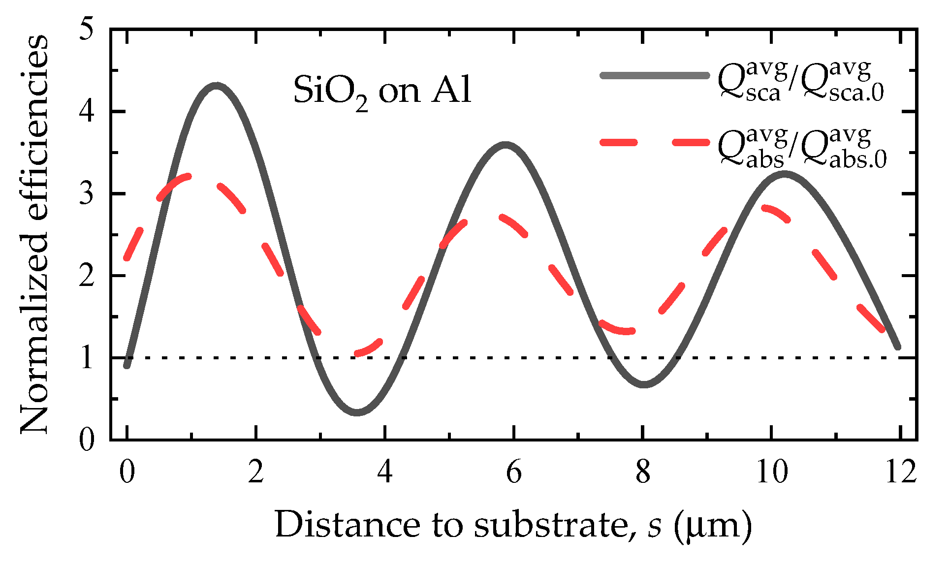
Therefore, there are two main mechanisms mediating the optical properties of particle above the substrate, i.e., the induced charges at the small gap and the standing waves for the large distance. Essentially, the standing waves roots in the interference interaction which owns periodicity. To illustrate the two mechanisms, we calculated the optical properties in a broader range of distances s from 0 μm to 12 μm. To further isolate the wavelength-dependent dispersion, we averaged the optical efficiencies of the SiO2 sphere over the spectral range of 8–14 μm, which were termed as Q sca avg , Q abs avg with the substrate and Q sca , 0 avg , Q abs , 0 avg in the free space. The superscript “avg” represents the wavelength average.
In this regard, we calculated the ratios of Q sca avg / Q sca , 0 avg and Q abs avg / Q abs , 0 avg as seen in Figure 6. The touching substrate strongly enhanced the absorption within the particle, which arose from the interaction between the induced and image charges. With the increased distance, however, it was intriguing to observe a periodic fluctuation of the normalized efficiencies, which was dominated by the role of standing waves. According to Refs. [25,26,63], the period of the oscillating far-field cross sections can be analyzed by the phase term of exp ( 2 i k d cos ϑ ) , where ϑ is the incident angle, k = 2 π / λ is the wavenumber, and d = a + s . Therefore, the optical properties will oscillate with the period of k ( a + s ) cos ϑ = π [26]. Taking the wavelength at the averaged value of 11 μm, we theoretically calculated the period of the distance Δs ≈ 4.5 μm, which agreed well with the numerical results in Figure 6. It should also be noted that the oscillated amplitudes damp with the increasing distance, which implies a gradually weakening role of the standing waves on the particle.
The strongly regulated efficiencies by the Al substrate suggest that the replacements of Q sca , Q abs with Q sca , 0 , Q abs , 0 should be careful within the featured s range in practical applications. For example, both average efficiencies considering the substrate suppress those in the free space over the almost whole range of s = 0–12 μm. Thus, even if the realistic SiO2 particles distributes randomly over the Al substrate, a distance-averaged efficiencies of the particle system still deviate largely from those in free space. This implies that the effects of the substrate should be further considered in the radiative property prediction by solving RTE in the particle-dispersed coatings.

3.2. Case 2: Single Al Sphere above SiO2 Substrate

Figure 7 shows the scattering and absorption efficiencies of the Al sphere above the SiO2 substrate. The radius of the sphere was 1 μm and the spectral range was from 7 to 14 μm. We first focused on the isolated Al particle without the substrate. In this case, the absorption efficiency was much smaller than 1, which was due to the large dielectric function of Al as seen in Figure 3b. In the Rayleigh approximation, the dominant dipole absorption of the particle in the free space is given by
Q abs , 0 q 12 ε 2 ( ε 1 + 2 ) 2 + ε 2 2 ,
where ε 1 and ε 2 represent the real and imaginary parts of the particle dielectric function, respectively. The squares of the dielectric function in the denominator produce the very small absorption within the Al particle in the infrared range. Furthermore, the scattering efficiencies Q sca , 0 can be about 100-fold larger than the absorption ones Q abs , 0 . Still, neither the absorption nor scattering efficiencies present any resonance structures for the isolated Al particle in the free space.
As for the Al spheres on the substrate (s = 0 μm), the resonance structures emerge based on the original plain lines. The position of the emerged resonances lies at about λ 9   μ m , which corresponds to the peaked wavelength of the SiO2 reflectance. At the peaked wavelength of about 9 μm, Q sca for the touching substrate reaches 6.4 that is nearly 7-fold higher than the isolated case Q sca , 0 . For absorption, Q abs for s = 0 μm obtains a 2-fold increase compared with Q abs , 0 . These suddenly enhanced scattering and absorption efficiencies may arise from the induced charges, which is explained in Section 3.1. However, the induced charges in this case enhance the scattering efficiencies largely rather than the absorption ones in Case 1.
With a slight increase in the distance s from 0 μm to 0.1 μm, the efficiencies decrease slightly implying the significant role of the induced charges for the small gap. When the distance increases further to 2 μm, the efficiencies suffer a large decrease which is due to the disappearing induced charges. As s increases from 2 μm to 4 μm, the scattering and absorption efficiencies increase again but hardly reach as large as those at small gaps (s < 0.1 μm).
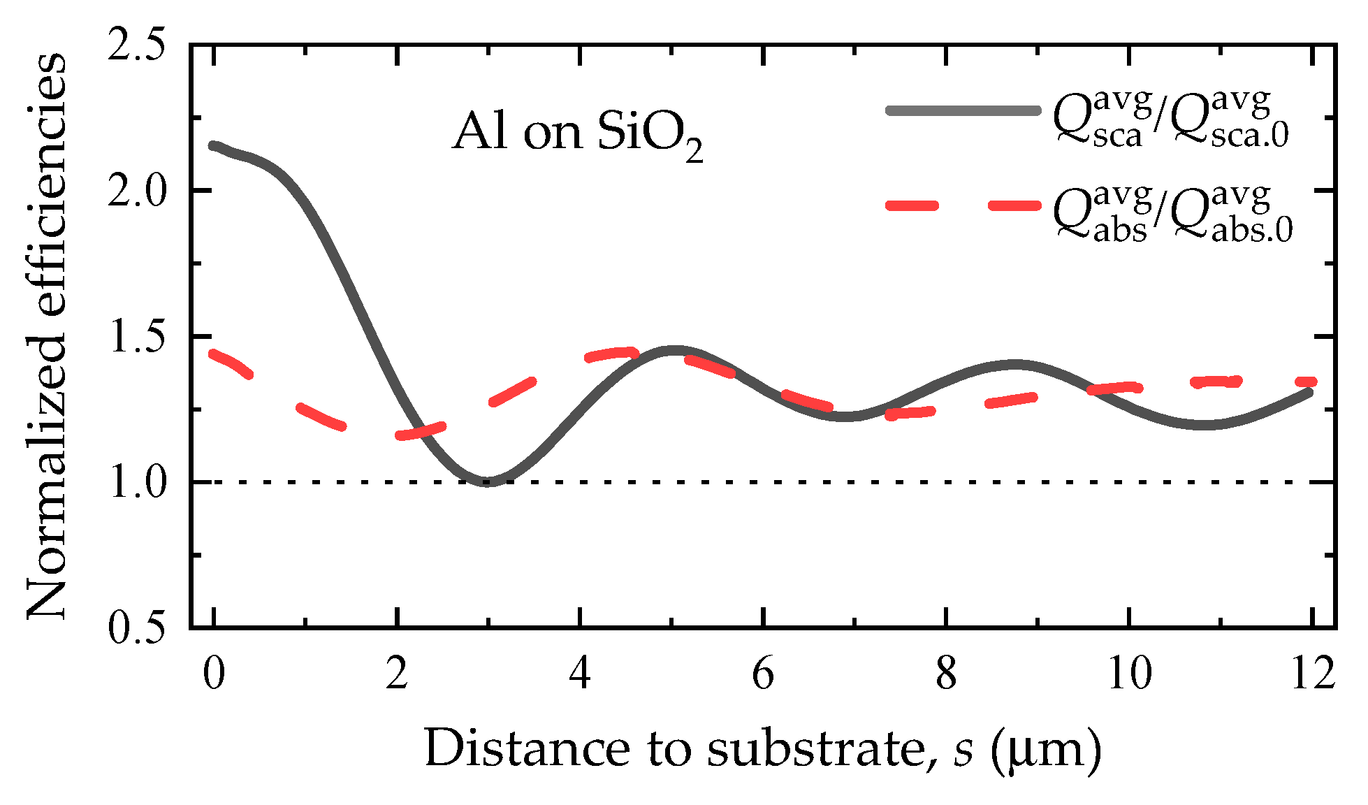
To give an overall trend in a broad range of distances, the ratios of the wavelength averaged efficiencies above the substrate to those in the free space, Q sca avg / Q sca , 0 avg and Q abs avg / Q abs , 0 avg , are plotted in Figure 8. Since the dielectric function and reflectance of SiO2 are strongly dispersive over the 8–14 μm band, the wavelength average serves to highlight the influence mechanism of the particle-substrate distance on the optical properties of the particle. The first thing to note is that the substrate will enhance the wavelength averaged scattering and absorption efficiencies according to the results of Q sca avg / Q sca , 0 avg 1 and Q abs avg / Q abs , 0 avg > 1 . Second, the small gaps (s < 1 μm) can prompt a 2-fold enhancement on the averaged scattering efficiencies, whereas Q sca avg / Q sca , 0 avg drops rapidly under 1.5 with the further increasing s. Third, the oscillations in the averaged efficiencies can be roughly seen from the curves, although they are not as clear as in Case 1. The dispersion in the reflectance of SiO2 may hinder the oscillation of standing waves which are closely related to the substrate reflectance according to Equation (11). After a rough estimation from Figure 8, the periods of the averaged scattering and absorption efficiencies were about 4 μm and 5 μm, respectively.
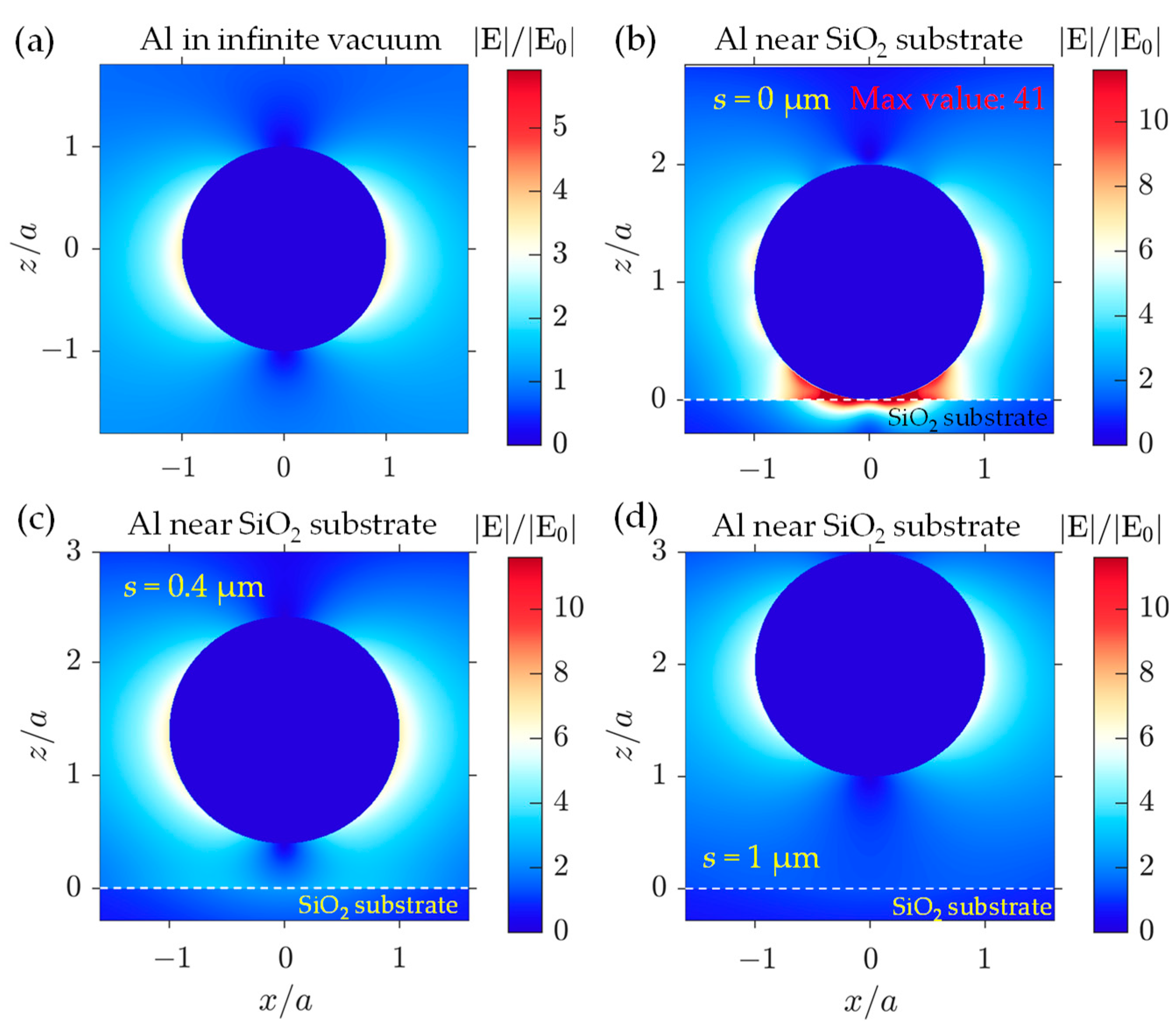
Figure 9 shows the normalized electric fields in the xz-plane for single Al particle with and without SiO2 substrate at λ = 9 μm. Figure 9a gives a typically non-resonant dipole pattern corresponding to an isolated metallic particle, where the fields distribute outside the particle and hardly penetrate the interior. In Figure 9b, the largely enhanced local field emerges near the particle-substrate junction, which illustrates the intense interaction between the induced and image charges. Furthermore, as seen from Figure 9b, many fields penetrate the SiO2 substrate rather than the Al particle. This corresponds to the substrate induced scattering enhancement in Figure 8. It is imperative to note in this case that the enhanced local fields by the touching substrate induce a scattering enhancement, which is different from the absorption enhancement in Case 1. However, we also note the common characteristic between the two cases, i.e., the substrate enhanced fields can penetrate the polar material rather than the high-impedance metallic material. With the enlarged gaps in Figure 9c,d, the distributed pattern of the fields converts back into that of the isolated particle, but the amplitude of fields is twice over that in Figure 9a. In this regard, the field enhancements at the enlarged gaps should result from the interference between the particle scattering and substrate reflectance, which can be qualitatively analyzed from Equation (11).

4. Conclusions

For particle-dispersed coatings, the dependent scattering between the particles and substrate is usually ignored in applications such as radiative cooling and infrared stealth. In this work, we systematically investigated the substrate regulated mechanisms on the infrared properties of a floating particle within the atmospheric radiative window of 8–14 µm. Using the T-matrix method and open-source codes, we calculated the scattering and absorption efficiencies for the two typical cases that are encountered frequently in realistic applications. Case 1 corresponds to a polar SiO2 sphere located near a metallic Al substrate, while Case 2 represents a metallic Al sphere above a polar SiO2 substrate. We revealed the two main mechanisms mediating the optical properties of particle above the substrate, which were the induced charges at the small particle-substrate gaps and the standing waves for the large gaps. The intense interaction between the induced and image charges enhanced the local fields near the narrow gap and penetrated the polar SiO2 materials with a small impedance. In this result, for the narrow gaps (<0.5a with a the sphere radius), the absorption and scattering cross sections were largely enhanced for the particles in Cases 1 and 2, respectively. For the large gaps, the interference between the particle scattered and substrate reflected waves dominates the substrate induced regulations. This interference structure (standing wave) prompts oscillating efficiency curves with the increasing gap sizes. According to a theoretical calculation, the oscillating period for the gap size was about 4.5a which agreed well with the numerical results.
Furthermore, to isolate the dispersion of the optical properties of materials, we averaged the scattering and absorption efficiencies of the particles within the atmospheric radiative window. For both Cases 1 and 2, it was found that ratio of the average efficiencies considering the substrate to those in the free space always surpassed 1 over a broad range of gap sizes (0–12a). We found that the dependent scattering between the particle and substrate strongly regulated the mid-infrared properties of the particles and cannot be safely ignored in practical applications. Our results may guide the accurate calculation and optimization for the apparent radiative properties of particle-dispersed coatings. In addition, the results of this work enlighten a potential regulation method for the apparent radiative property of particle-dispersed coatings by controlling the settlement distribution of the pigments.

Author Contributions

All authors contributed to this study’s conception; methodology, F.G., S.Z. and L.M.; software, F.G.; validation, F.G., S.Z. and L.M.; investigation, F.G., S.Z. and L.M.; resources, W.Z.; data curation, F.G., S.Z. and W.Z.; writing—original draft preparation, F.G., S.Z. and W.Z.; writing—review and editing, F.G., S.Z. and W.Z.; visualization, F.G., S.Z. and W.Z.; supervision, W.Z. and L.L.; project administration, W.Z.; funding acquisition, W.Z. and S.Z. All authors have read and agreed to the published version of the manuscript.

Funding

This research was funded by the National Natural Science Foundation of China (Grant No. 52006127) and the Natural Science Foundation of Shandong Province (Grant Nos. ZR2022QE245 and ZR2020QE194).

Institutional Review Board Statement

Not applicable.

Informed Consent Statement

Not applicable.

Data Availability Statement

The data presented in this study are available on request from the corresponding author.

Acknowledgments

The authors would like to sincerely thank D. W. Mackowski for his guidance in using the MSTM program and his illuminating discussion on the scattering enhancement mechanism.

Conflicts of Interest

The authors declare no conflict of interest.

References

  1. Bao, H.; Yan, C.; Wang, B.X.; Fang, X.; Zhao, C.Y.; Ruan, X.L. Double-layer nanoparticle-based coatings for efficient terrestrial radiative cooling. Sol. Energy Mater. Sol. Cells 2017, 168, 78–84. [Google Scholar] [CrossRef]
  2. Chen, M.J.; Pang, D.; Chen, X.Y.; Yan, H.J. Investigating the effective radiative cooling performance of random dielectric microsphere coatings. Int. J. Heat Mass Transf. 2021, 173, 121263. [Google Scholar] [CrossRef]
  3. Zhao, Y.W.; Pang, D.; Chen, M.J.; Chen, Z.; Yan, H.J. Scalable aqueous processing-based radiative cooling coatings for heat dissipation applications. Appl. Mater. Today 2022, 26, 101298. [Google Scholar] [CrossRef]
  4. Cheng, Z.M.; Han, H.; Wang, F.Q.; Yan, Y.Y.; Shi, X.H.; Liang, H.X.; Zhang, X.P.; Shuai, Y. Efficient radiative cooling coating with biomimetic human skin wrinkle structure. Nano Energy 2021, 89, 106377. [Google Scholar] [CrossRef]
  5. Wang, G.H.; Zhang, Y.; Zhang, D.H.; Fan, J.P. Design and calculation of low infrared transmittance and low emissivity coatings for heat radiative applications. Int. J. Miner. Metall. Mater. 2012, 19, 179–184. [Google Scholar] [CrossRef]
  6. Liang, J.; Li, W.; Xu, G.Y.; Meng, X.; Liu, K.; Tan, S.J. Preparation and characterization of the colored coating with low infrared emissivity based on nanometer pigment. Prog. Org. Coat. 2018, 115, 74–78. [Google Scholar] [CrossRef]
  7. Liu, Y.F.; Xie, J.L.; Luo, M.; Peng, B.; Xu, C.; Deng, L.J. The synthesis and optical properties of Al/MnO2 composite pigments by ball-milling for low infrared emissivity and low lightness. Prog. Org. Coat. 2017, 108, 30–35. [Google Scholar] [CrossRef]
  8. Liu, Z.H.; Ban, G.D.; Ye, S.T.; Liu, W.Y.; Liu, N.; Tao, R. Infrared emissivity properties of infrared stealth coatings prepared by water-based technologies. Opt. Mater. Express 2016, 6, 3716–3724. [Google Scholar] [CrossRef]
  9. Chen, S.; Yuan, L.; Weng, X.L.; Deng, L.J. Modeling emissivity of low-emissivity coating containing horizontally oriented metallic flake particles. Infrared Phys. Technol. 2014, 67, 377–381. [Google Scholar] [CrossRef]
  10. Dias, C.; Veloso, R.C.; Maia, J.; Ramos, N.M.M.; Ventura, J. Oversight of radiative properties of coatings pigmented with TiO2 nanoparticles. Energy Build. 2022, 271, 112296. [Google Scholar] [CrossRef]
  11. Zhai, Q.W.; Zhu, Q.Z. Radiative cooling film with self-cleaning function. Sol. Energy Mater. Sol. Cells 2021, 228, 111117. [Google Scholar] [CrossRef]
  12. Huang, Z.F.; Ruan, X.L. Nanoparticle embedded double-layer coating for daytime radiative cooling. Int. J. Heat Mass Transf. 2017, 104, 890–896. [Google Scholar] [CrossRef]
  13. Cheng, Z.M.; Shuai, Y.; Gong, D.Y.; Wang, F.Q.; Liang, H.X.; Li, G.Q. Optical properties and cooling performance analyses of single-layer radiative cooling coating with mixture of TiO2 particles and SiO2 particles. Sci. China Technol. Sci. 2021, 64, 1017–1029. [Google Scholar] [CrossRef]
  14. Mishra, B.R.; Sundaram, S.; Varghese, N.J.; Sasihithlu, K. Disordered metamaterial coating for daytime passive radiative cooling. AIP Adv. 2021, 11, 105218. [Google Scholar] [CrossRef]
  15. Song, K.L.; Xie, M.; Ai, Q.; Yang, L.; Liu, H.T.; Tan, H.P. Effects of size, volume fraction, and orientation of metallic flake particles on infrared radiation characteristics of Al/acrylic resin composite coatings. Prog. Org. Coat. 2020, 145, 105680. [Google Scholar] [CrossRef]
  16. Mishchenko, M.I.; Dlugach, J.M.; Yurkin, M.A.; Bi, L.; Cairns, B.; Liu, L.; Panetta, R.L.; Travis, L.D.; Yang, P.; Zakharova, N.T. First-principles modeling of electromagnetic scattering by discrete and discretely heterogeneous random media. Phys Rep. 2016, 632, 1–75. [Google Scholar] [CrossRef]
  17. Modest, M.F. Radiative Heat Transfer; Academic Press: Cambridge, MA, USA, 2013. [Google Scholar]
  18. Bohren, C.F.; Huffman, D.R. Absorption and Scattering of Light by Small Particles; Wiley: New York, NY, USA, 1983. [Google Scholar]
  19. He, Y.; Zhang, X.; Guan, J. Preparation and properties of EPDM-Based composite coatings with low infrared emissivity. J. Energy Eng. 2016, 142, 04016011. [Google Scholar] [CrossRef]
  20. Chou, K.S.; Lu, Y.C. The application of nanosized silver colloids in far infrared low-emissive coating. Thin Solid Film. 2007, 515, 7217–7221. [Google Scholar] [CrossRef]
  21. Fu, Y.; An, Y.D.; Xu, Y.K.; Dai, J.G.; Lei, D.Y. Polymer coating with gradient-dispersed dielectric nanoparticles for enhanced daytime radiative cooling. Ecomat 2022, 4, e12169. [Google Scholar] [CrossRef]
  22. Johnson, B.R. Light scattering from a spherical particle on a conducting plane. I: Normal incidence. J. Opt. Soc. Am. A 1992, 9, 1341–1351. [Google Scholar] [CrossRef]
  23. Johnson, B.R. Calculation of light scattering from a spherical particle on a surface by the multipole expansion method. J. Opt. Soc. Am. A 1995, 13, 326–337. [Google Scholar] [CrossRef]
  24. Lermé, J.; Bonnet, C.; Broyer, M.; Cottancin, E.; Manchon, D.; Pellarin, M. Optical properties of a particle above a dielectric interface: Cross sections, benchmark calculations, and analysis of the intrinsic substrate effects. J. Chem. Phys. 2013, 117, 6383–6398. [Google Scholar] [CrossRef]
  25. Videen, G. Light scattering from a sphere on or near a surface. J. Opt. Soc. Am. A 1991, 8, 483–489. [Google Scholar] [CrossRef]
  26. Mackowski, D.W. The extension of the multiple sphere T matrix code to include multiple plane boundaries and 2-D periodic systems. J. Quant. Spectrosc. Radiat. Transf. 2022, 290, 108292. [Google Scholar] [CrossRef]
  27. Ramezan pour, B.; Mackowski, D.W. Radiative transfer equation and direct simulation prediction of reflection and absorption by particle deposits. J. Quant. Spectrosc. Radiat. Transf. 2017, 189, 361–368. [Google Scholar] [CrossRef]
  28. Bobbert, P.A.; Vlieger, J. Light scattering by a sphere on a substrate. Phys. A Stat. Mech. Its Appl. 1986, 137, 209–242. [Google Scholar] [CrossRef]
  29. Miroshnichenko, A.E.; Evlyukhin, A.B.; Kivshar, Y.S.; Chichkov, B.N. Substrate-induced resonant magnetoelectric effects for dielectric nanoparticles. ACS Photonics 2015, 2, 1423–1428. [Google Scholar] [CrossRef]
  30. Evlyukhin, A.B.; Bozhevolnyi, S.I. Resonant unidirectional and elastic scattering of surface plasmon polaritons by high refractive index dielectric nanoparticles. Phys. Rev. B 2015, 92, 245419. [Google Scholar] [CrossRef]
  31. Loke, V.L.Y.; Menguc, M.P.; Nieminen, T.A. Discrete-dipole approximation with surface interaction: Computational toolbox for MATLAB. J. Quant. Spectrosc. Radiat. Transf. 2011, 112, 1711–1725. [Google Scholar] [CrossRef]
  32. Mizeikis, V.; Kowalska, E.; Ohtani, B.; Juodkazis, S. Frequency- and polarization-dependent optical response of asymmetric spheroidal silver nanoparticles on dielectric substrate. Phys. Status Solidi Rapid Res. Lett. 2010, 4, 268–270. [Google Scholar] [CrossRef]
  33. Markovich, D.L.; Ginzburg, P.; Samusev, A.K.; Belov, P.A.; Zayats, A.V. Magnetic dipole radiation tailored by substrates: Numerical investigation. Opt. Express 2014, 22, 10693–10702. [Google Scholar] [CrossRef] [PubMed]
  34. Sakurai, A.; Kawamata, T. Electromagnetic resonances of solar-selective absorbers with nanoparticle arrays embedded in a dielectric layer. J. Quant. Spectrosc. Radiat. Transf. 2016, 184, 353–359. [Google Scholar] [CrossRef]
  35. Hutter, T.; Elliott, S.R.; Mahajan, S. Interaction of metallic nanoparticles with dielectric substrates: Effect of optical constants. Nanotechnology 2013, 24, 035201. [Google Scholar] [CrossRef] [PubMed]
  36. Waxenegger, J.; Trügler, A.; Hohenester, U. Plasmonics simulations with the MNPBEM toolbox: Consideration of substrates and layer structures. Comput. Phys. Commun. 2015, 193, 138–150. [Google Scholar] [CrossRef]
  37. Hohenester, U.; Trügler, A. MNPBEM—A Matlab toolbox for the simulation of plasmonic nanoparticles. Comput. Phys. Commun. 2012, 183, 370–381. [Google Scholar] [CrossRef]
  38. Yamamoto, N.; Ohtani, S.; Garcia de Abajo, F.J. Gap and Mie plasmons in individual silver nanospheres near a silver surface. Nano Lett. 2011, 11, 91–95. [Google Scholar] [CrossRef]
  39. Pinchuk, A.; Hilger, A.; von Plessen, G.; Kreibig, U. Substrate effect on the optical response of silver nanoparticles. Nanotechnology 2004, 15, 1890–1896. [Google Scholar] [CrossRef]
  40. Knight, M.W.; Wu, Y.; Lassiter, J.B.; Nordlander, P.J.; Halas, N.J. Substrates matter: Influence of an adjacent dielectric on an individual plasmonic nanoparticle. Nano Lett. 2009, 9, 2188–2192. [Google Scholar] [CrossRef]
  41. Yang, C.; Liang, P.; Tang, L.S.; Zhou, Y.F.; Cao, Y.T.; Wu, Y.X.; Zhang, D.; Dong, Q.M.; Huang, J.; He, P. Synergistic effects of semiconductor substrate and noble metal nano-particles on SERS effect both theoretical and experimental aspects. Appl. Surf. Sci. 2018, 436, 367–372. [Google Scholar] [CrossRef]
  42. Liu, C.B.; Wang, C.X.; Chen, J.H.; Su, Y.J.; Qiao, L.J.; Zhou, J.; Bai, Y. Ultrasensitive frequency shifting of dielectric Mie resonance near metallic substrate. Research 2022, 2022, 9862974. [Google Scholar] [CrossRef]
  43. Yang, Y.; Miller, O.D.; Christensen, T.; Joannopoulos, J.D.; Soljacic, M. Low-Loss plasmonic dielectric nanoresonators. Nano Lett. 2017, 17, 3238–3245. [Google Scholar] [CrossRef] [PubMed]
  44. Sung, L.P.; Mulholland, G.W.; Germer, T.A. Polarized light-scattering measurements of dielectric spheres upon a silicon surface. Opt. Lett. 1999, 24, 866–868. [Google Scholar] [CrossRef] [PubMed]
  45. Rocco, D.; De Angelis, C.; de Ceglia, D.; Carletti, L.; Scalora, M.; Vincenti, M.A. Dielectric nanoantennas on epsilon-near-zero substrates: Impact of losses on second order nonlinear processes. Opt. Commun. 2020, 456, 124570. [Google Scholar] [CrossRef]
  46. Marino, G.; Gigli, C.; Rocco, D.; Lemaître, A.; Favero, I.; De Angelis, C.; Leo, G. Zero-Order Second Harmonic Generation from AlGaAs-on-Insulator Metasurfaces. ACS Photonics 2019, 6, 1226–1231. [Google Scholar] [CrossRef]
  47. Gili, V.F.; Carletti, L.; Chouchane, F.; Wang, G.; Ricolleau, C.; Rocco, D.; Lemaître, A.; Favero, I.; Ghirardini, L.; Finazzi, M.; et al. Role of the substrate in monolithic AlGaAs nonlinear nanoantennas. Nanophotonics 2018, 7, 517–521. [Google Scholar] [CrossRef]
  48. Gili, V.F.; Carletti, L.; Locatelli, A.; Rocco, D.; Finazzi, M.; Ghirardini, L.; Favero, I.; Gomez, C.; Lemaître, A.; Celebrano, M.; et al. Monolithic AlGaAs second-harmonic nanoantennas. Opt. Express 2016, 24, 15965–15971. [Google Scholar] [CrossRef]
  49. Abou-Hamdan, L.; Coudrat, L.; Bidault, S.; Krachmalnicoff, V.; Haïdar, R.; Bouchon, P.; De Wilde, Y. Transition from phononic to geometrical Mie modes measured in single subwavelength polar dielectric spheres. ACS Photonics 2022, 9, 2295–2303. [Google Scholar] [CrossRef]
  50. Qi, Z.Q.; Li, J.H.; Chen, P.; Zhang, L.L.; Ji, K. Tunable high-Q factor substrate for selectively enhanced raman scattering. Photonics 2022, 9, 755. [Google Scholar] [CrossRef]
  51. Li, X.X.; Jia, C.C.; Ma, B.J.; Wang, W.; Fang, Z.Y.; Zhang, G.Q.; Guo, X.F. Substrate-induced interfacial plasmonics for photovoltaic conversion. Sci. Rep. 2015, 5, 14497. [Google Scholar] [CrossRef]
  52. Li, G.C.; Zhang, Y.L.; Lei, D.Y. Hybrid plasmonic gap modes in metal film-coupled dimers and their physical origins revealed by polarization resolved dark field spectroscopy. Nanoscale 2016, 8, 7119–7126. [Google Scholar] [CrossRef]
  53. Jan, J.; Pavel, Z.; Alexandr, J.; Mojmir, S.; Pavel, P.; Miroslav, L. Behavior of nanoparticle and microparticle in the standing wave trap. In Proceedings of the 12th Czech-Slovak-Polish Optical Conference on Wave and Quantum Aspects of Contemporary Optics, Velke Losiny, Czech Republic, 12–15 September 2000; pp. 318–325. [Google Scholar]
  54. Cheng, Z.M.; Wang, F.Q.; Wang, H.; Liang, H.X.; Ma, L.X. Effect of embedded polydisperse glass microspheres on radiative cooling of a coating. Int. J. Therm. Sci. 2019, 140, 358–367. [Google Scholar] [CrossRef]
  55. Wang, H.D.; Xue, C.H.; Guo, X.J.; Liu, B.Y.; Ji, Z.Y.; Huang, M.C.; Jia, S.T. Superhydrophobic porous film for daytime radiative cooling. Appl. Mater. Today 2021, 24, 101100. [Google Scholar] [CrossRef]
  56. Cheng, Z.M.; Wang, F.Q.; Gong, D.Y.; Liang, H.X.; Shuai, Y. Low-cost radiative cooling blade coating with ultrahigh visible light transmittance and emission within an “atmospheric window”. Sol. Energy Mater. Sol. Cells 2020, 213, 110563. [Google Scholar]
  57. Mackowski, D.W. Multiple Sphere T Matrix Fortran-90 Code, Version 4.0. Available online: https://www.eng.auburn.edu/~dmckwski/scatcodes/ (accessed on 8 June 2022).
  58. Palik, E.D. Handbook of Optical Constants of Solids; Academic Press: Cambridge, MA, USA, 1998; Volume 1. [Google Scholar]
  59. Haynes, E.W.M. CRC Handbook of Chemistry and Physics; CRC Press: Boca Raton, FL, USA, 2016. [Google Scholar]
  60. Wang, T.; Li, P.; Hauer, B.; Chigrin, D.N.; Taubner, T. Optical properties of single infrared resonant circular microcavities for surface phonon polaritons. Nano Lett. 2013, 13, 5051–5055. [Google Scholar] [CrossRef] [PubMed]
  61. Wu, Z.Q.; Yang, J.L.; Manjunath, N.K.; Zhang, Y.J.; Feng, S.R.; Lu, Y.H.; Wu, J.H.; Zhao, W.W.; Qiu, C.Y.; Li, J.F.; et al. Gap-Mode surface-plasmon-enhanced photoluminescence and photoresponse of MoS2. Adv. Mater. 2018, 30, e1706527. [Google Scholar] [CrossRef]
  62. Xifre-Perez, E.; Shi, L.; Tuzer, U.; Fenollosa, R.; Ramiro-Manzano, F.; Quidant, R.; Meseguer, F. Mirror-image-induced magnetic modes. ACS Nano 2013, 7, 664–668. [Google Scholar] [CrossRef]
  63. Wriedt, T.; Doicu, A. Light scattering from a particle on or near a surface. Opt. Commun. 1998, 152, 376–384. [Google Scholar] [CrossRef]
Figure 1. Schematic diagram of two geometric models studied in this paper. (a) Case 1: single SiO2 spherical particle placed on the Al substrate; (b) case 2: single Al spherical particle located on the SiO2 substrate. The coordinate system is shown, where z = 0 is set at the substrate surface. The radius of the sphere is a, while the gap size is represented by s. The p-polarized light is normally incident on the substrates with the incident wave vector k.
Photonics 10 00476 g001
Figure 2. (a) The absorption cross sections of a gold sphere above the glass substrate calculated by MSTM and BEM [36]. (b) The infrared scattering efficiencies of a SiO2 sphere in a vacuum are calculated by the MSTM method and Mie theory.
Photonics 10 00476 g002
Figure 3. The dielectric functions of (a) SiO2 and (b) Al. It is noted that the complex dielectric function is represented as ε = ε 1 + i ε 2 . (c) The normal reflectance of semi-infinite Al and SiO2 substrates. The spectral range is selected for 8–14 μm.
Photonics 10 00476 g003
Figure 4. Mid-infrared properties of a SiO2 sphere on the Al substrate versus the wavelength and particle-to-substrate distance s, where curves of different colors correspond to different distances s of particles to the substrate: (a) scattering and (b) absorption efficiencies. For convenience, the efficiencies of a free particle without the substrate Q sca , 0 and Q abs , 0 are also shown. The radius of the SiO2 sphere is 1 μm.
Photonics 10 00476 g004
Figure 5. Normalized electric fields |E|/|E0| in xz-plane of a SiO2 particle with a = 1 μm, where |E0| is the amplitude of the incident electric field. The incident wavelength is selected at the resonance position of λ = 8.9 μm. (a) The electric fields of the SiO2 sphere in the free space. (bd) The electric fields of the SiO2 sphere above Al substrate with the varied distances of (b) s = 0 μm, (c) s = 0.4 μm, and (d) s = 1 μm. It should be noted that the maximum number of normalized fields in (b) is 54.
Photonics 10 00476 g005
Figure 6. The wavelength-averaged efficiencies of the SiO2 particle on the Al substrate versus the particle-to-substrate distance s. Both the scattering Q sca avg and absorption efficiencies Q abs avg are averaged over the spectral range of 8–14 μm. Note that the averaged efficiencies with the substrate are normalized with those without the substrate Q sca , 0 avg , Q abs , 0 avg .
Photonics 10 00476 g006
Figure 7. Infrared properties of an Al sphere on the SiO2 substrate versus the wavelength and particle-to-substrate distance s, where curves of different colors correspond to different distances s of particles to the substrate: (a) scattering and (b) absorption efficiencies. For convenience, the efficiencies of a free particle without the substrate are also shown. The radius of the Al sphere is 1 μm.
Photonics 10 00476 g007
Figure 8. The wavelength-averaged efficiencies of the Al particle on the SiO2 substrate versus the particle-to-substrate distance s. Both the scattering Q sca avg and absorption efficiencies Q abs avg are averaged over the spectral range of 8–14 μm. Note that the averaged efficiencies with the substrate are normalized with those without the substrate Q sca , 0 avg , Q abs , 0 avg .
Photonics 10 00476 g008
Figure 9. Normalized electric fields |E|/|E0| in xz-plane of an Al particle with a = 1 μm, where |E0| is the amplitude of the incident electric field. The incident wavelength is selected at λ = 9 μm. (a) The electric fields of the Al sphere in the free space. (bd) The electric fields of the Al sphere above SiO2 substrate with the varied distances of (b) s = 0 μm, (c) s = 0.4 μm, and (d) s = 1 μm. It should be mentioned that the maximum number of normalized electric fields in (b) is 41.
Photonics 10 00476 g009
Disclaimer/Publisher’s Note: The statements, opinions and data contained in all publications are solely those of the individual author(s) and contributor(s) and not of MDPI and/or the editor(s). MDPI and/or the editor(s) disclaim responsibility for any injury to people or property resulting from any ideas, methods, instructions or products referred to in the content.