Article

Particle Swarm Optimized Compact, Low Loss 3-dB Power Splitter Enabled by Silicon Columns in Silicon-on-Insulator

1
State Key Laboratory of Functional Materials for Informatics, Shanghai Institute of Microsystem and Information Technology, Chinese Academy of Sciences, Shanghai 200050, China
2
University of Chinese Academy of Sciences, Beijing 100049, China
*
Author to whom correspondence should be addressed.
Photonics 2023, 10(4), 419; https://doi.org/10.3390/photonics10040419
Submission received: 25 February 2023 / Revised: 20 March 2023 / Accepted: 26 March 2023 / Published: 7 April 2023
(This article belongs to the Section Optical Communication and Network)

Abstract

:
We demonstrate a 3-dB power splitter optimized by an enhanced particle swarm optimization algorithm based on a curved directional coupler, with a set of silicon columns introduced into the coupling region. The proposed device exhibits compact size, low loss and low wavelength dependence in the O-band. We employ the particle swarm optimization algorithm to engineer the dispersion by designing the radius of the silicon columns automatically. The demonstrated 3-dB power splitter enabled by silicon columns in silicon-on-insulator can achieve multiple performance metrics simultaneously according to our simulation results, with a compact footprint as small as 11.9 µm, low excess loss as low as 0.04 dB and broad 3-dB operational bandwidth of 60 nm with transmission fluctuations within 0.05 in the wavelength range from 1270 to 1330 nm. This work pioneers the silicon columns in the coupling region and adopts an enhanced particle swarm optimization algorithm to optimize device properties, providing significant potential for application in large-scale PICs as well as offering a new degree of freedom in the design of power splitters.

1. Introduction

With the explosive growth of datacom and telecom, photonic integrated chips (PICs) have experienced a boom as they offer greater data capacity and faster transfer rates [1]. Silicon photonics are compatible with mature Complementary-Metal-Oxide-Semiconductor (CMOS) processes and have a higher refractive index contrast on standard silicon-on-insulator (SOI) [2]. Therefore, the dimensions of the devices based on silicon photonics can be substantially reduced, which is conductive to large-scale photonic integration. PICs consist of many optical components that perform different functions, thus enabling optical interconnections. As a fundamental building block, the power splitters are an integral part of PICs [3]. Power splitters can realize beam splitting and are also widely used in wavelength division (de)multiplexing (WDM) [4,5], passive optical networks (PON) [6,7], optical neural networks (ONN) [8,9], optical switches [10,11], optical phased arrays (OPA) [12,13], modulators [14,15,16], etc. Commonly used power splitters include multimode interference couplers (MMIs), Y-junction couplers, directional couplers (DCs), etc. Multimode interference is a popular choice based on the self-imaging principle for designing power splitters. MMIs can realize large bandwidth and fabrication tolerance, but in general they suffer from output imbalance and excess loss in their operating band [17,18]. The Y-junction coupler is also routinely adopted for power splitting because of its compact footprint and broadband. However, the loss of these couplers is high when the angle of the Y-branch in the structure is not guaranteed to be less than a specific value [19]. The regular DCs have the merits of compact dimensions and low loss, but they are subject to dispersion leading to a high wavelength dependence [20]. Thereby the practical operational bandwidth is limited. For a traditional DC, a broad bandwidth can potentially be achieved by engineering the super-mode dispersion when some special structures are introduced. Several approaches to break through the bandwidth limits for coupling structures have been proposed, including asymmetric DCs, subwavelength grating (SWG) based DCs and adiabatic DCs (ADCs). The asymmetric DCs introduce asymmetric waveguides in the coupling region to engineer dispersion. When using asymmetric DCs, one can obtain a compact footprint as well as a wavelength-insensitive power-splitting ratio. However, the operation bandwidth of the DCs mentioned above are difficult to extended further [21]. The SWG structure for engineering the mode dispersion can be also introduced in the coupling region to obtain a large operational bandwidth and compact dimension. In [22], the demonstrated SWG-based DC can achieve a 100 nm operational bandwidth from 1500nm to 1600 nm with an insertion loss of 0.2 dB. The disadvantage is that the DC is very sensitive to the fabrication process, which poses considerable challenges for manufacturing. We can also adopt an adiabatic taper in the coupling region of regular DCs to break the limits of wavelength dependence. Benefiting from adiabatic single-mode evolution, ADCs can surmount fabrication imperfections well and offer large bandwidth. In [23], the proposed ADC exhibits an excellent fabrication tolerance and large operational bandwidth of 100 nm, ranging from 1260nm to 1360 nm with a significant device footprint of 240 μm. Inevitably, even if multiple performance metrics are met, the large dimension of ADCs is not conducive to large-scale photonic integration. Therefore, it is necessary to propose a power splitter with multiple performance characteristics simultaneously.
In this paper, we propose a pioneering curved directional coupler optimized by a particle swarm optimization (PSO) algorithm based on silicon columns dispersion engineering. By introducing a group of silicon columns in the coupling region, we use the PSO algorithm to automatically optimize the structure to obtain the desired power splitting ratio. Through FDTD simulation, we present the simulation results of a 3-dB power splitter. According to the simulation results using the PSO algorithm, the proposed device has a small coupling dimension of 11.9 μm and a low loss of 0.04 dB. The device can achieve 3-dB power splitting with less than ±0.05 transmission fluctuation in the waveband of 1270 nm to 1330 nm. The proposed device can be extensively employed in high-density PICs and offers new degrees of freedom in the design of power splitters.

2. Device Schematic and Operation Principle

2.1. Device Schematic

Figure 1a shows the schematic of the proposed device. Light is launched into the input port and divided into the cross and bar port. According to the coupled-mode theory [24], the output power of the proposed coupler is expressed by
P b a r = P 0 1 k c K 2 s i n 2 K L
P c r o s s = P 0 k c K 2 s i n 2 K L
In the above equations, P 0 is the input power, P b a r and P c r o s s refer to the output power in the bar port and cross port, respectively, L is the length of the coupled waveguide, k c is the coupling coefficient, and K is denoted as
K = β 1 β 2 2 2 + k c 2
In Equation (3), β 1 and β 2 refer to the propagation constant of the coupled waveguides. The amplitude term of k c K 2 indicates the maximum coupling efficiency between the two parallel cores, while the phase term of K L stands for the location where the maximum coupling efficiency is reached. The output optical power of the directional coupler varies sinusoidally between 0 and P 0 accordingly. It can be assumed that the power splitting and the propagation constants are highly interrelated. We can obtain a maximum coupling efficiency of 100% when β 1 = β 2 (symmetric); in this case, the optical power launched to the input port completely transfers to another waveguide. For 3-dB couplers, these symmetric couplers (regular directional couplers) exhibit a high wavelength dependence at the 3-dB splitting wavelength since there is a periodic 100% power coupling between the two waveguides, in correspondence to the crossing point. When β 1 β 2 (asymmetric), the maximum coupling efficiency is less than 100% and the input power cannot be fully transferred to another waveguide. In this case, a wavelength-insensitive 3-dB power splitting can be obtained by designing the asymmetry of the two waveguides to satisfy the k c K 2 ≈ 0.5. The asymmetric coupler achieves the difference of the propagation constant between the two waveguides by marginally changing their widths. Similarly, a curved directional coupler with silicon columns introduced can provide a difference in propagation constants between two waveguides with the same waveguide width. With the propagation constants difference afforded by silicon columns, we can further engineer the dispersion to enhance the operational bandwidth. Our proposed device has a smaller transverse dimension for the same mode coupling length than that of a straight waveguide based directional coupler, which is more conducive to large-scale integration of the device. In addition, due to the simple structure of the silicon columns and our existing fabrication conditions, we can realize them efficiently. To better demonstrate the design principles of our work, we have divided it into five sections, as shown in Figure 1b.
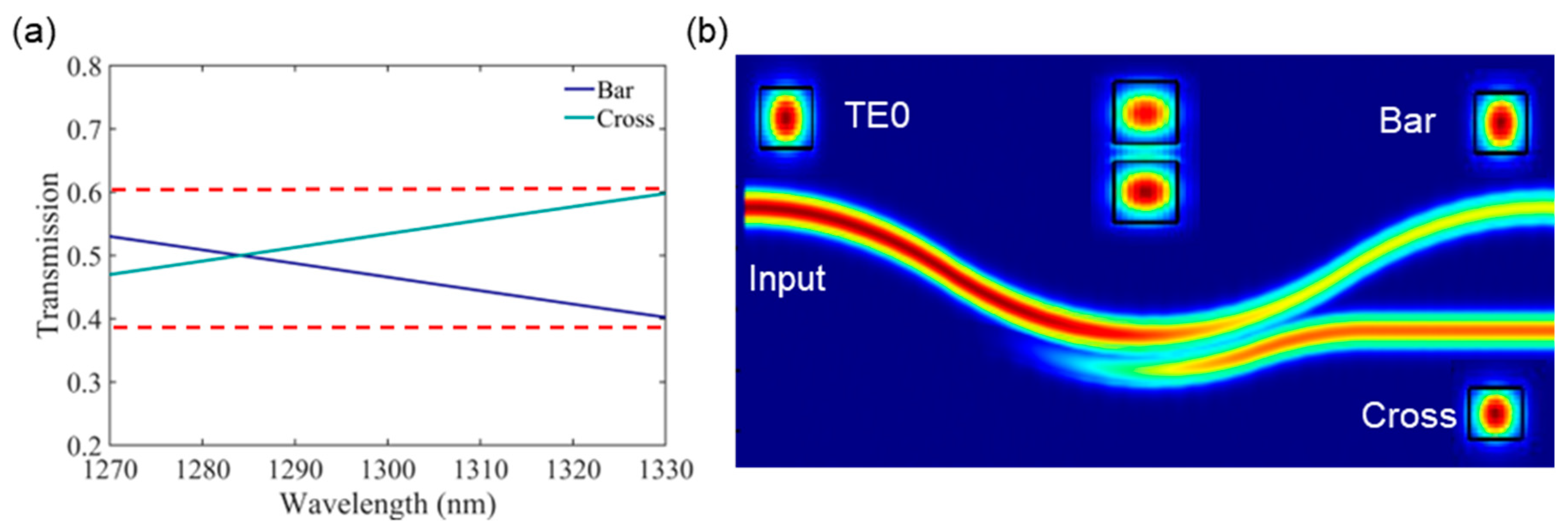
Region Ⅰ is the input end of the device, consisting of a pair of straight waveguides. When light transmits from the input, we must ensure that the waveguide width meets the single-mode condition. Furthermore, the gap between the waveguides needs to be large enough to minimize mode crosstalk. Region Ⅱ is a transition region, comprised of a set of curved waveguides. This structure is primarily designed to bridge the input and coupling regions, with the gap between the curved waveguides decreasing from the left to the right. Region Ⅲ is the mode coupling section of the device. This part of the structure is composed of curved waveguides with a fixed gap and a set of silicon columns. The dispersion of the device is engineered by optimizing the radius of the silicon columns. Powered by particle swarm optimized silicon columns, the device is automatically optimized for a large operational bandwidth when compared to an unoptimized original structure with a small operational bandwidth that fails to achieve the target power splitting ratio. In the meantime, the device introduces a high refractive index silicon structure that allows for a more compact footprint to achieve the target power splitting ratio. Region Ⅳ, also a transition section, consists of a group of curved waveguides that are separated gradually. This section is used to connect the coupling region to the output and allows the mode to be decoupled steadily into the different output ports. Region Ⅴ is the output end of the device and consists of a set of straight waveguides that support integration with more devices. The gap between the output waveguides needs to be large enough to avoid output mode crosstalk. The proposed device can be fabricated by a standard CMOS process. Based on a conventional SOI platform, the device incorporates a 220 nm thick silicon layer, a 2 µm thick oxide layer, and a 2 µm thick cladding layer. To verify that a coupler based on the above structure can achieve the desired power splitting, we present a 3-dB power splitter using a PSO algorithm. For each iteration of the PSO algorithm, we primarily used the commercial software Lumerical 2.5D finite difference time domain (FDTD) to simulate the structural properties, with the TE fundamental mode as the excitation source and PML as the boundary conditions. Finally, the optimized results were verified using 3D FDTD to ensure the accuracy of the output. The initial structural parameters before optimization are listed in Table 1. The transmission curve and light field profile of the device without the introduction of the silicon columns are depicted in Figure 2a,b. The device has a poor operational bandwidth and cannot achieve the 3-dB power splitting. It is common to effectively tune its dispersion by introducing some special structure so that it is less sensitive to wavelength. Our proposed work can automatically optimize the radius of the introduced silicon columns in accordance with the set target value by using an intelligent optimization algorithm to ultimately achieve an output that satisfies the objective threshold. To a large extent, this work can reduce labor costs and time investment.

2.2. Mathematical Model

The design of conventional silicon optical devices generally follows Maxwell’s equations. The parameters of device are then manually adjusted, and the structure is simulated to obtain the properties. Inevitably, such a design methodology is time-consuming and often results in larger device sizes. However, optimization algorithms such as PSO [25], GA algorithms [26] and direct binary search [27] can assist in the design to achieve the target properties more quickly and unambiguously. This study uses PSO as the dominant optimization algorithm due to its significant tradeoff between convergence speed and optimal objective values when compared to other algorithms. The PSO algorithm is an algorithm oriented towards the simultaneous optimization of multiple objective values, with stochastic and iterative properties. The PSO algorithm was inspired by a flock of birds searching for food and models the sharing and iteration of information among birds. The particle swarm continuously updates its current position and velocity and uses an evaluation function to calculate whether the target value is reached. The PSO algorithm considers the exploring direction of both the individual particle and the whole swarm. Meanwhile, the algorithm retains the ability to explore randomly in order to avoid falling into the trap of local optimum. Through parameter adjustment, the ability to skip out of the local trap can be enhanced. To raise the stochastic searching capability, we employed a speed-constrained PSO optimization algorithm. Compared to other optimization algorithms, the speed-constrained PSO has a faster convergence rate and higher accuracy. As shown in Equations (4)–(6), the mathematical model of the PSO can be expressed as follows:
v i , t + 1 d = ω v i , t d r a n d + c 1 r a n d p i , t d x i , t d + c 2 r a n d p g , t d x i , t d
x i , t + 1 d = x i , t d + v i , t + 1 d
ω = ω max t ω max ω min G
We define a D-dimensional variable space in which the position, velocity, individual optimal position and global optimal position of the particle are denoted as follows:
X i = x i 1 , x i 2 , x i 3 , , x i d , , x i D
V i = v i 1 , v i 2 , v i 3 , , v i d , , v i D
P i = p i 1 , p i 2 , p i 3 , , p i d , , p i D
P g = p g 1 , p g 2 , p g 3 , , p g d , , p g D
In the above equations, i, t and G represent the i-th particle, the t-th iteration and the total number of iterations, respectively. ω, c1 and c2 represent the inertial, social and cognitive parameters, respectively. These are critical control parameters in this algorithm, with a significant impact on the convergence speed and robustness. It should be noted that the speed-constrained multi-objective PSO algorithm introduces a variable inertia constant to further improve its robustness against falling into local traps. It will adjust the global search capability of the particle swarm with each iteration, helping to find the optimal value faster. The rand in Equation (4) is a random number that takes values in the range (0,1). We incorporate device optimization for silicon columns dispersion tuning and eventually set the values of the social and cognitive parameters to 1.2 and 1.4 after several trials, respectively. ω is finally set to a variable in the range (0.4,1). For the PSO algorithm, we chose a total number of particles of 30 and a number of dimensions of 22. It is essential to be aware that the number of dimensions of the particles refers to the number of silicon columns contained in our proposed device and that the position of the particles is associated with the radius of the silicon columns. The detailed parameters concerning the PSO algorithm are shown in Table 2.
In the specific simulation, we set 80 frequency points in the wavelength range from 1270 nm to 1330 nm. To weigh the proximity of the position of the individual particle to the target output, we define the figure-of-merit (FoM) as the evaluation function of the PSO algorithm, as shown in Equation (11):
F o M = 1 Σ i = 1 80 T b a r λ i T a i m + T c r o s s λ i T a i m
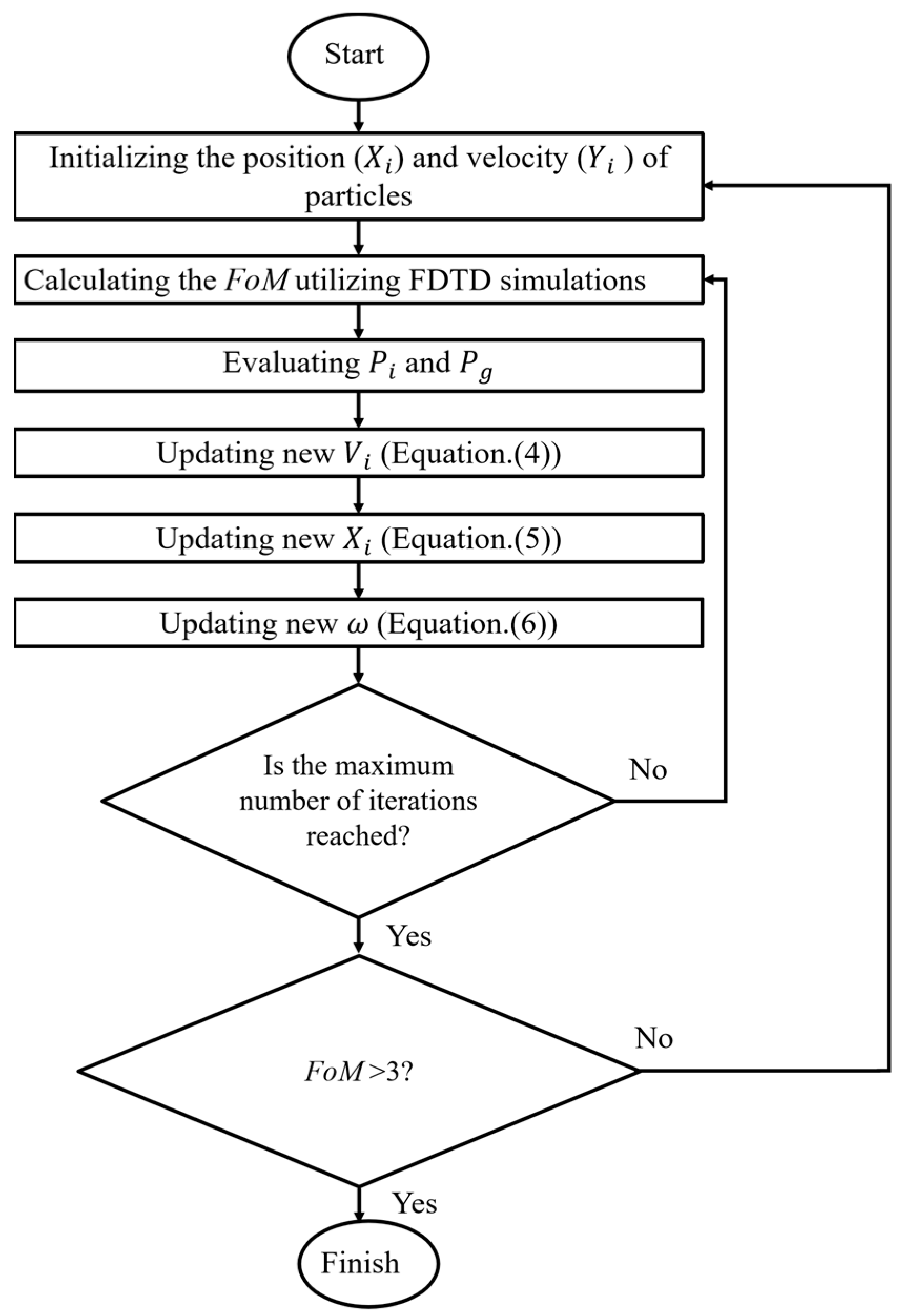
T b a r λ i , T c r o s s λ i represent the transmission at the bar port and the cross port at wavelength λ i . T a i m represents the target power splitting ratio. FoM [28] is primarily a function of the difference between the transmission of the device at different wavelengths from the bar and cross ports and the target power splitting ratio for each iteration. With this definition, we can intuitively see whether the pre-defined power splitting ratio is being approached. The FoM varies as the particles continuously search, and the optimal FoM for individual particle and the optimal FoM for particles swarm will be recorded until better FoM emerge to replace them with each iteration. The overall FoM curve versus the number of iterations demonstrates the PSO algorithm’s ongoing search for the optimal value. To better illustrate the PSO algorithm’s optimization process, the flow chart of the algorithm is shown in Figure 3. The threshold of FoM is closely linked to our defined Equation (11). We have chosen FoM > 3; this is a threshold derived from the experience of many iterations. After the algorithm iteration, a Boolean operation is conducted upon whether the optimal FoM > 3 to decide whether to terminate the procedure or start a new round of simulation computation [29].

3. Results and Discussion

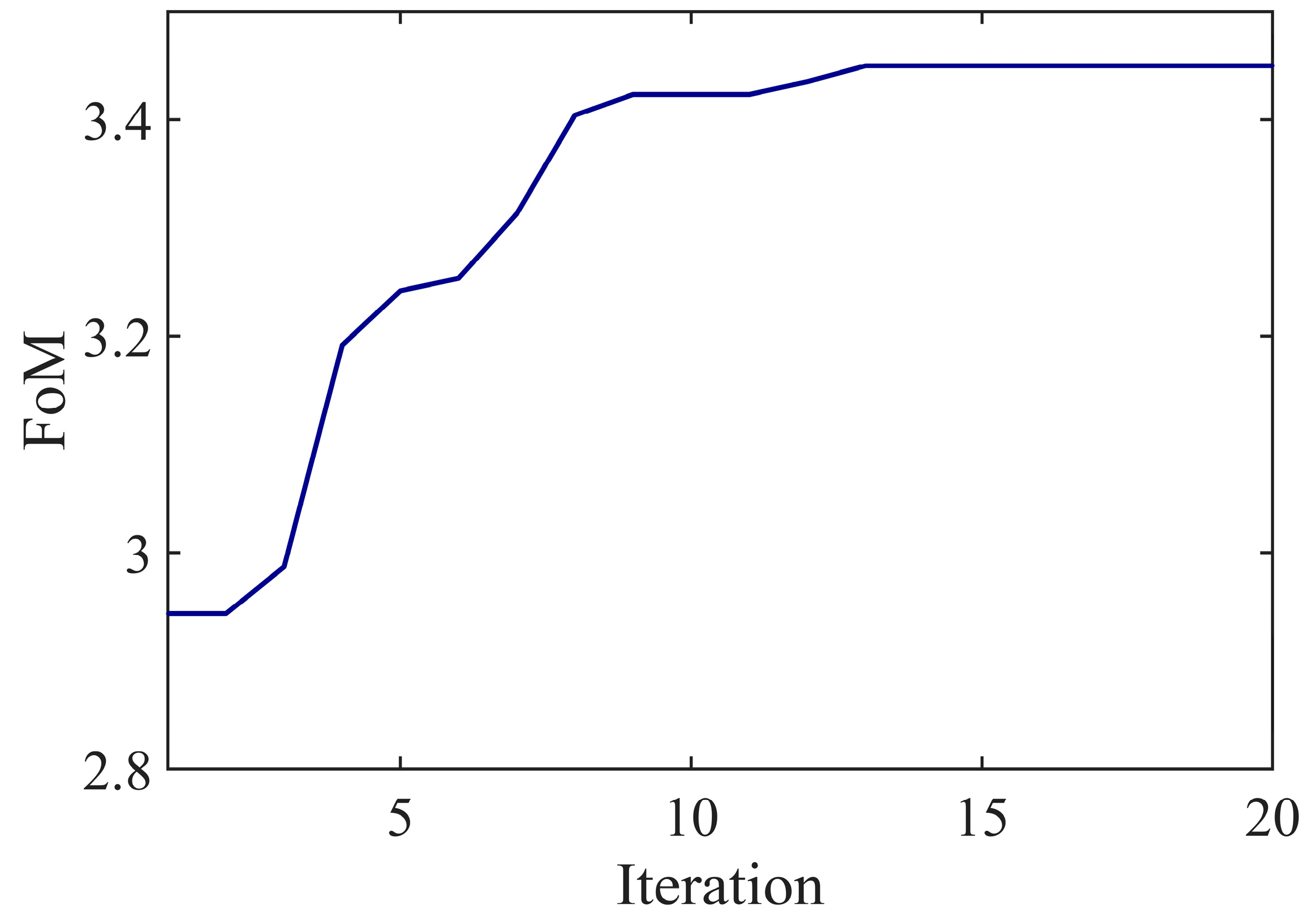
The optimization for the proposed device is performed with a combination of the PSO algorithm and Var FDTD. We adopt the MATLAB API to call FDTD for the integration of PSO and FDTD. The computational resources used to run our algorithm are a server with a 4.1 Ghz Core-i7 CPU and 160 GB RAM. The specific simulation involved in each iteration is Var FDTD, with TE modes used as excitation. After several optimizations of the PSO algorithm, we obtained the best device design solution in a total time of about 5 h. As shown in Figure 4, we show the convergence plot of the PSO optimization. The particle swarm gradually finds the maximum FoM value of 3.45 after 13 iterations and remains stable throughout the subsequent exploration.
In the case of optimum design, the output gives the radii of all silicon columns, as shown in Table 3. Then we used FDTD to verify the properties of the structure. The simulated transmission curves are shown in Figure 5a for the wavelength range from 1270 nm to 1330 nm. Tbar, Tcross refer to the optical transmission at the bar and cross ports, respectively. It is apparent that the power splitter achieves 3-dB power splitting in the operational waveband with a fluctuation below 0.05; this is within an acceptable range of transmission fluctuations [30,31]. When compared to the unoptimized device, this power splitter meets the design targets for a 3-dB power splitter. A diagram of the propagating modes at different positions of the device are shown in Figure 5b, as well as an overall light field diagram. It is not difficult to see that the mode remains stable during transmission and splits out smoothly into two beams after passing through the coupling region. Furthermore, we have calculated the excess loss (EL) of this optimized device. We define the EL as follows:
E L = 10 log 10 T b a r + T c r o s s
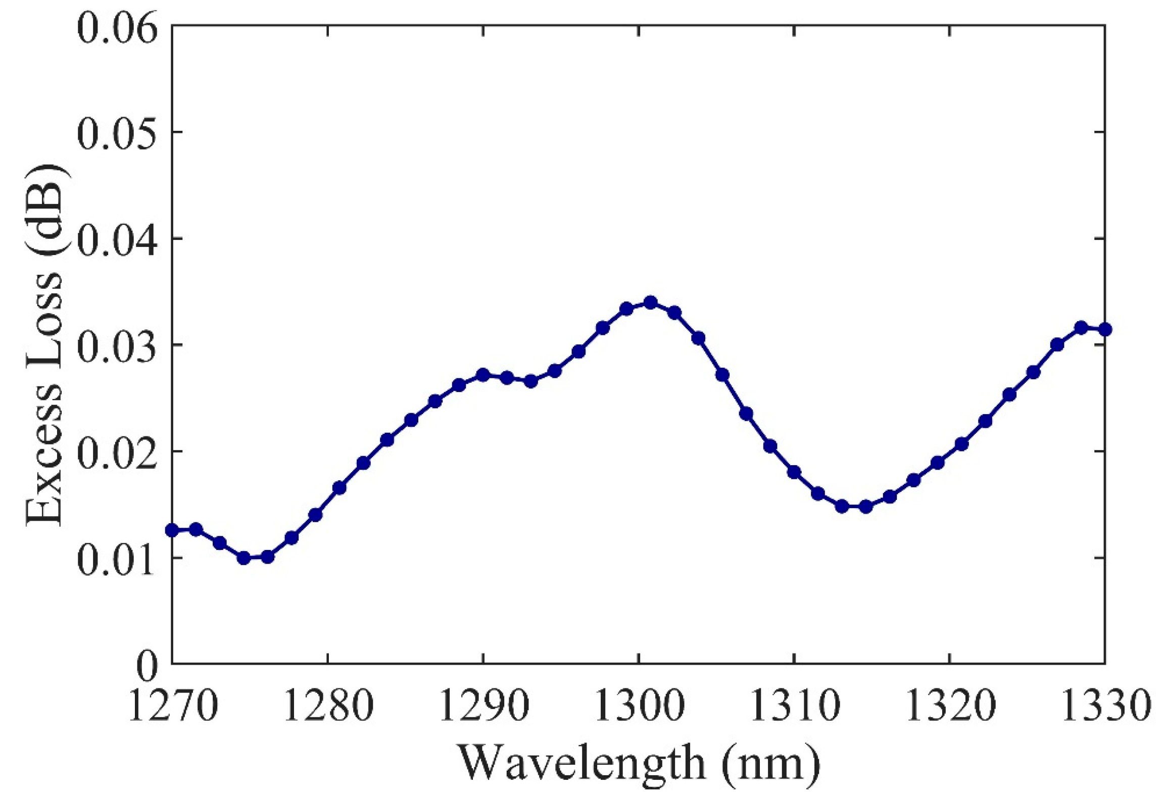
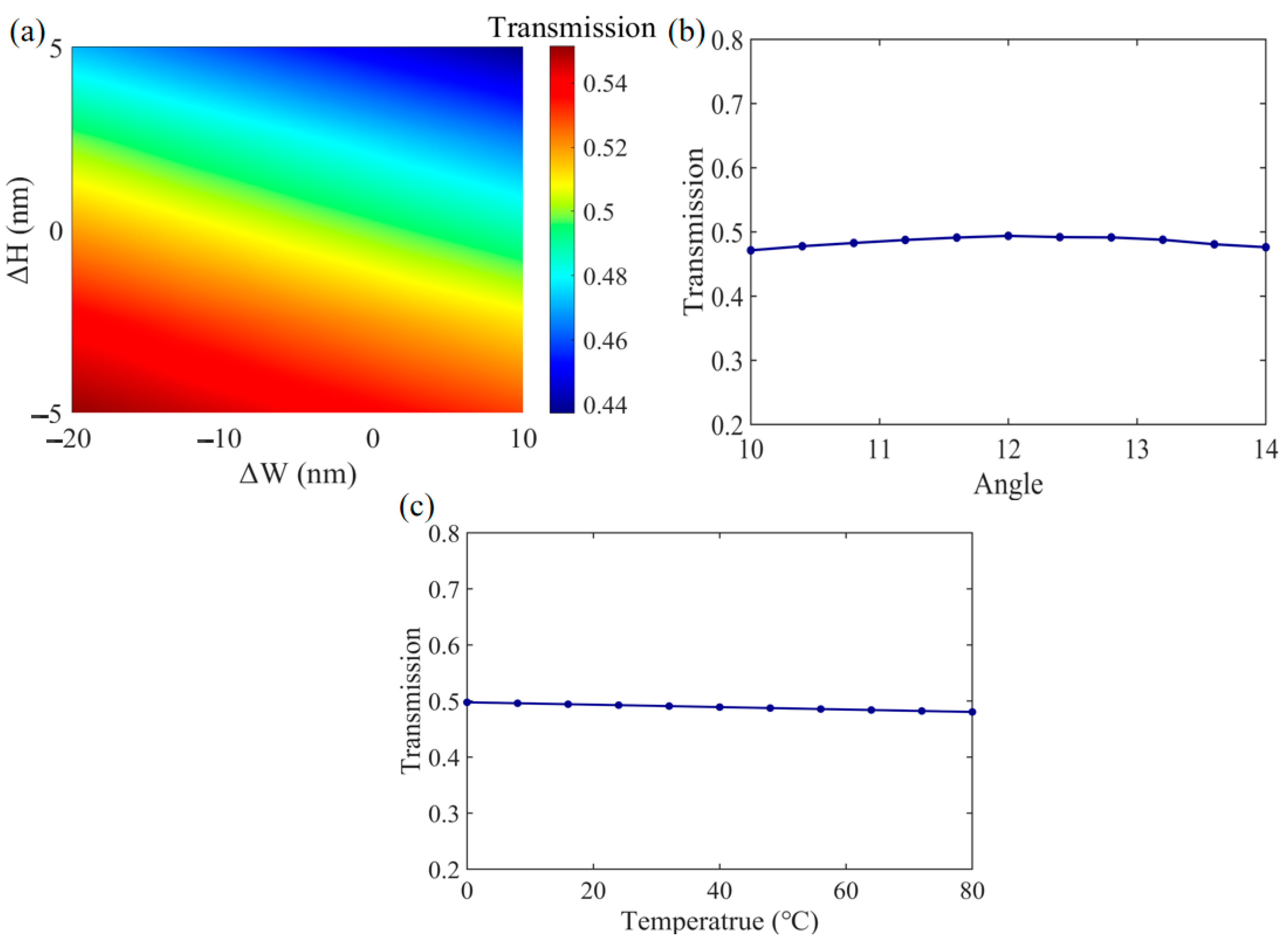
The curve of EL versus wavelength for this device is shown in Figure 6. Based on the simulation data, the EL of the device is less than 0.04 dB. Moreover, the effective coupling dimension of the device is approximately 11.9 µm. Although the bend is added, the device loss is sufficiently small, and the increased loss is also very minor when compared to a straight waveguide-based DC with the same coupling length. In addition, we have analyzed robustness in terms of fabrication variation and temperature deviation. The devices have been simulated with a waveguide width deviation from −20 nm to 10 nm and waveguide height deviation of ±5 nm at 1300 nm, as shown in Figure 7a. In the simulation of fabrication tolerance, we investigate the situation where the waveguide gap is fixed and both waveguides deviate simultaneously. In addition, we have also analyzed the robustness of the device against variations in bending angle. As shown in Figure 7b, the transmission of the device at the bar port remains in a stable range, with the bending angle varying between 10 and 14 degrees. The simulation results show that the device has excellent robustness to fabrication variation. We have also simulated the power splitting performance of the device over a temperature range from 0 to 80 °C at 1300 nm. As shown in Figure 7c, the device still works stably. This indicates that the PSO algorithm optimized power splitter, with a small footprint, low loss and low wavelength dependence, has the potential to be used in high density PICs.
The study innovatively introduces silicon columns in the coupling region to engineer dispersion, achieving a small footprint, low loss and a large operational bandwidth. Our proposed splitter provides the asymmetry with silicon columns between the propagation constants to satisfy the wavelength-insensitive 3-dB power splitting. In addition, the work was completed in a shorter optimization time than manual adjustment. Moreover, the coupling dimensions of the device can be made more compact. The introduction of silicon structures enhances the mode coupling strength, making it less necessary to have a longer dimension to obtain the target power splitting ratio. Device optimization enabled by the PSO algorithm can complete the exploration for the optimal structure more efficiently, benefiting from the variable inertia constants in the PSO algorithm. This allows the search capability of the particle swarm to be continuously adapted as the search progresses.
The comparisons between the state-of-the-art imbalanced couplers with the coupler demonstrated in this work are summarized in Table 4. Our proposed particle-swarm-optimized power splitter based on silicon column enables a small footprint, low loss and low wavelength dependence. The device shows significant potential for application in large-scale PICs, and offers new degrees of freedom in the design of power splitters.

4. Conclusions

In conclusion, we propose a 3-dB curved directional coupler optimized by a PSO algorithm based on silicon column dispersion engineering. The device exhibits compact size, low loss and low wavelength dependence in O-band. We then combine this with a PSO algorithm to automatically optimize the structure for a target power splitting ratio. Remarkably, our enhanced PSO algorithm allows for flexible search capabilities and the ability to escape local traps. In this case, our silicon-columns based curved directional coupler exhibits an excess loss as low as 0.04 dB and a coupling footprint as small as 11.9 µm according to our simulation results. Moreover, this work can achieve a 3-dB power splitting ratio with fluctuations within 0.05 in the wavelength range from 1270 nm to 1330 nm. Our proposed device obtains a tradeoff of multiple performance metrics and offers significant potential for application in large-scale PICs, as well as providing new degrees of freedom in the design of power splitters.

Author Contributions

Conceptualization, X.L. and F.G.; methodology, X.L. and Y.Z.; software, X.L. and Z.Z.; validation, X.L. and H.L.; formal analysis, X.L. and Z.Z.; investigation, X.L. and H.L.; resources, X.L.; data curation, X.L.; writing—original draft preparation, X.L.; writing—review and editing, F.G., Y.Z. and X.L.; visualization, X.L.; supervision, F.G. and Y.Z.; All authors have read and agreed to the published version of the manuscript.

Funding

This work was funded by National Key Research and Development Program of China [2022YFB2803100]; National major scientific research instrument development project [22127901]; Shanghai Sailing Program [22YF1456700].

Institutional Review Board Statement

Not applicable.

Informed Consent Statement

Not applicable.

Data Availability Statement

Relevant data are available from the authors upon reasonable request.

Conflicts of Interest

The authors declare no conflict of interest.

References

  1. Pitris, S.; Moralis-Pegios, M.; Alexoudi, T.; Ban, Y.; De Heyn, P.; Van Campenhout, J.; Lambrecht, J.; Ramon, H.; Yin, X.; Bauwelinck, J.; et al. O-Band Silicon Photonic Transmitters for Datacom and Computercom Interconnects. J. Light. Technol. 2001, 37, 5140–5148. [Google Scholar] [CrossRef]
  2. Siew, S.Y.; Li, B.; Gao, F.; Zheng, H.Y.; Zhang, W.; Guo, P.; Xie, S.W.; Song, A.; Dong, B.; Luo, L.W.; et al. Review of Silicon Photonics Technology and Platform Development. J. Light. Technol. 2021, 39, 4374–4389. [Google Scholar] [CrossRef]
  3. Zhu, J.; Chao, Q.; Huang, H.; Zhao, Y.; Li, Y.; Tao, L.; She, X.; Liao, H.; Huang, R.; Zhu, Z.; et al. Compact, broadband, and low-loss silicon photonic arbitrary ratio power splitter using adiabatic taper. Appl. Opt. 2021, 60, 413–416. [Google Scholar] [CrossRef]
  4. Zhang, Z.; Liu, T.; Zhang, K.; Li, M.; Liu, H.; Li, H.; Niu, P.; Gu, E. Bidirectional grating based interleaved angled MMI for high-uniformity wavelength division (de)multiplexing and surface-normal fiber packaging. Appl. Opt. 2021, 60, 5615–5622. [Google Scholar] [CrossRef] [PubMed]
  5. Chen, G.F.R.; Choi, J.W.; Sahin, E.; Tan, D.T.H.; Ng, D.K.T. On-chip 1 by 8 coarse wavelength division multiplexer and multi-wavelength source on ultra-silicon-rich nitride. Opt. Express 2019, 27, 23549–23557. [Google Scholar] [CrossRef]
  6. Xue, X.; Ji, W.; Huang, K.; Li, X.; Zhang, S. Tunable Multiwavelength Optical Comb Enabled WDM-OFDM-PON With Source-Free ONUs. IEEE Photonics J. 2018, 10, 1–8. [Google Scholar] [CrossRef]
  7. Xu, M.; Liu, C.; Subramaniam, S. PODCA: A passive optical data center network architecture. J. Opt. Commun. Netw. 2018, 10, 409–420. [Google Scholar] [CrossRef]
  8. Totovic, A.; Giamougiannis, G.; Tsakyridis, A.; Pleros, N.; Lazovsky, D. Programmable photonic neural networks combining WDM with coherent linear optics. Sci. Rep. 2022, 12, 5605. [Google Scholar] [CrossRef] [PubMed]
  9. Moralis-Pegios, M.; Mourgias-Alexandris, G.; Tsakyridis, A.; Giamougiannis, G.; Totovic, A.; Dabos, G.; Passalis, N.; Kirtas, M.; Tefas, A.; Pleros, N.; et al. Neuromorphic Silicon Photonics and Hardware-Aware Deep Learning for High-Speed Inference. J. Light. Technol. 2022, 40, 3243–3254. [Google Scholar] [CrossRef]
  10. Qing, F.; Jun, F.S.; Tsung-Yang, L.; Hong, C.; Ming, B.Y.; Guo, Q.L.; Dim-Lee, K. Ultralow Power Silicon Photonics Thermo-Optic Switch With Suspended Phase Arms. IEEE Photonics Technol. Lett. 2011, 23, 525–527. [Google Scholar]
  11. Chu, T.; Yamada, H.; Ishida, S.; Arakawa, Y. Compact 1 × N thermo-optic switches based on silicon photonic wire waveguides. Opt. Express 2005, 13, 10109–10114. [Google Scholar] [CrossRef]
  12. Heck, M.J.R. Highly integrated optical phased arrays: Photonic integrated circuits for optical beam shaping and beam steering. Nanophotonics 2017, 6, 93–107. [Google Scholar] [CrossRef]
  13. Poulton, C.V.; Yaacobi, A.; Cole, D.B.; Byrd, M.J.; Raval, M.; Vermeulen, D.; Watts, M.R. Coherent solid-state LIDAR with silicon photonic optical phased arrays. Opt. Lett. 2017, 42, 4091–4094. [Google Scholar] [CrossRef]
  14. Thomson, D.J.; Hu, Y.; Reed, G.T.; Fedeli, J.-M. Low Loss MMI Couplers for High Performance MZI Modulators. IEEE Photonics Technol. Lett. 2010, 22, 1485–1487. [Google Scholar] [CrossRef] [Green Version]
  15. Liao, L.; Samara-Rubio, D.; Morse, M.; Liu, A.; Hodge, D.; Rubin, D.; Keil, U.D.; Franck, T. High speed silicon Mach-Zehnder modulator. Opt. Express 2005, 13, 3129–3135. [Google Scholar] [CrossRef] [Green Version]
  16. Palmer, R.; Alloatti, L.; Korn, D.; Schindler, P.C.; Baier, M.; Bolten, J.; Wahlbrink, T.; Waldow, M.; Dinu, R.; Freude, W.; et al. Low Power Mach–Zehnder Modulator in Silicon-Organic Hybrid Technology. IEEE Photonics Technol. Lett. 2013, 25, 1226–1229. [Google Scholar] [CrossRef]
  17. Xu, K.; Liu, L.; Wen, X.; Sun, W.; Zhang, N.; Yi, N.; Sun, S.; Xiao, S.; Song, Q. Integrated photonic power divider with arbitrary power ratios. Opt. Lett. 2017, 42, 855–858. [Google Scholar] [CrossRef] [PubMed] [Green Version]
  18. Zanzi, A.; Brimont, A.; Griol, A.; Sanchis, P.; Marti, J. Compact and low-loss asymmetrical multimode interference splitter for power monitoring applications. Opt. Lett. 2016, 41, 227–229. [Google Scholar] [CrossRef]
  19. Zhang, Y.; Yang, S.; Galland, C.; Baehr-Jones, T.; Hochberg, M.; Eu-Jin Lim, A.; Lo, G.-Q. A compact and low loss Y-junction for submicron silicon waveguide. Opt. Express 2013, 21, 1310–1316. [Google Scholar] [CrossRef] [PubMed]
  20. Yamada, H.; Tao, C.; Ishida, S.; Arakawa, Y. Optical directional coupler based on Si-wire waveguides. IEEE Photonics Technol. Lett. 2005, 17, 585–587. [Google Scholar] [CrossRef]
  21. Lu, Z.; Yun, H.; Wang, Y.; Chen, Z.; Zhang, F.; Jaeger, N.A.F.; Chrostowski, L. Broadband silicon photonic directional coupler using asymmetric-waveguide based phase control. Opt. Express 2015, 23, 3795–3808. [Google Scholar] [CrossRef] [PubMed]
  22. Xu, L.; Wang, Y.; Kumar, A.; El-Fiky, E.; Mao, D.; Tamazin, H.; Jacques, M.; Xing, Z.; Saber, M.G.; Plant, D.V. Compact high-performance adiabatic 3-dB coupler enabled by subwavelength grating slot in the silicon-on-insulator platform. Opt. Express 2018, 26, 29873–29885. [Google Scholar] [CrossRef]
  23. Mao, D.; Alam, M.S.; Zhang, J.; Zhu, M.; Koh, P.; Plant, D.V.; Wang, Y.; El-Fiky, E.; Xu, L.; Kumar, A.; et al. Adiabatic Coupler With Design-Intended Splitting Ratio. J. Light. Technol. 2019, 37, 6147–6155. [Google Scholar] [CrossRef]
  24. Haus, H.A.; Huang, W. Coupled-mode theory. Proc. IEEE 1991, 79, 1505–1518. [Google Scholar] [CrossRef] [Green Version]
  25. Shiratori, R.; Nakata, M.; Hayashi, K.; Baba, T. Particle swarm optimization of silicon photonic crystal waveguide transition. Opt. Lett. 2021, 46, 1904–1933. [Google Scholar] [CrossRef]
  26. Fu, P.H.; Tu, Y.C.; Huang, D.W. Broadband optical waveguide couplers with arbitrary coupling ratios designed using a genetic algorithm. Opt. Express 2016, 24, 30547–30561. [Google Scholar] [CrossRef]
  27. Xu, Y.; Xie, T.; Zhang, Z.; Ma, H.; Yang, J. Ultra-compact power splitters with low loss in arbitrary direction based on inverse design method. Photonics 2021, 8, 516. [Google Scholar] [CrossRef]
  28. Leng, L.; Jin, M.; Lin, Z.; Zhang, C.; Ding, D.; Jiang, W. Ultra-Broadband, Fabrication Tolerant Optical Coupler for Arbitrary Splitting Ratio Using Particle Swarm Optimization Algorithm. IEEE Photonics J. 2020, 12, 1–12. [Google Scholar] [CrossRef]
  29. Hung, Y.J.; Chen, C.H.; Lu, G.X.; Liang, F.C.; Chung, H.C.; Tseng, S.Y. Compact and robust 2 × 2 fast quasi-adiabatic 3-dB couplers on SOI strip waveguides. Opt. Laser Technol. 2022, 145, 107485. [Google Scholar] [CrossRef]
  30. Wang, Y.; Lu, Z.; Ma, M.; Yun, H.; Zhang, F.; Jaeger, N.A.F.; Chrostowski, L. Compact Broadband Directional Couplers Using Subwavelength Gratings. IEEE Photonics J. 2016, 8, 1–8. [Google Scholar]
  31. Halir, R.; Maese-Novo, A.; Ortega-Monux, A.; Molina-Fernández, I.; Wangüemert-Pérez, J.G.; Cheben, P.; Xu, D.X.; Schmid, J.H.; Janz, S. Colorless directional coupler with dispersion engineered sub-wavelength structure. Opt. Express 2012, 20, 13470–13477. [Google Scholar] [CrossRef] [PubMed] [Green Version]
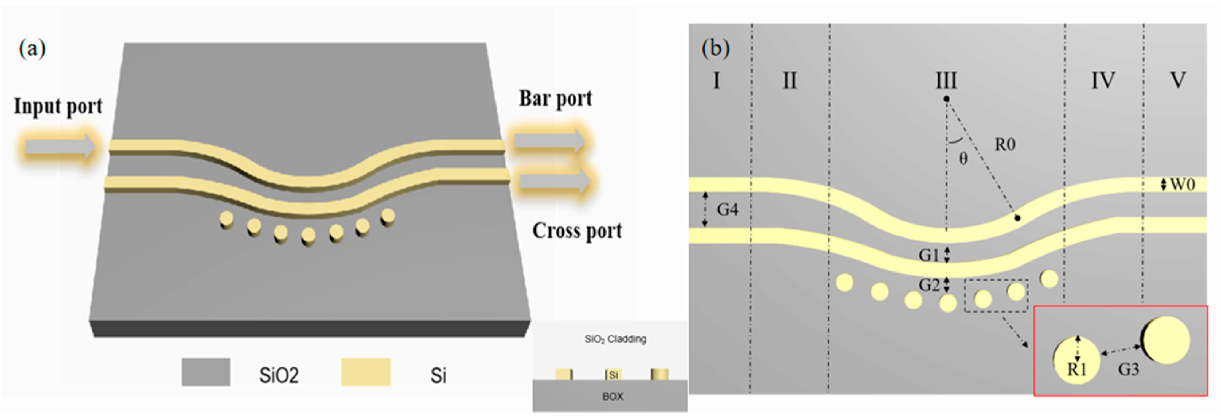
Figure 1. (a) Schematic view of the proposed power splitter with a group of silicon columns introduced into the coupling region in standard silicon-on-insulator. (b) The top view of the schematic and the geometric parameters of the proposed 3-dB power splitter.
Photonics 10 00419 g001
Figure 2. (a) Simulated transmission curve of the initial structure without silicon columns introduced. (b) Simulated light field profile of the initial structure with TE0 mode excited.
Photonics 10 00419 g002
Figure 3. The flow chart of PSO algorithm.
Photonics 10 00419 g003
Figure 4. FoM curve of the device at each iteration.
Photonics 10 00419 g004
Figure 5. (a) Simulated transmission curves of the PSO optimized device with silicon columns introduced. (b) Simulated Light field profile of the PSO optimized device obtained with TE0 mode excited.
Photonics 10 00419 g005
Figure 6. The simulated EL of the optimal device.
Photonics 10 00419 g006
Figure 7. (a) Simulated fabrication tolerance to the deviation of waveguide width and thickness. (b) Simulated transmission curve from bar port at wavelength of 1300 nm with angle varying from 10 to 14 degrees. (c) The simulated temperature sensitivity of the proposed power splitter from 0 to 80 degrees at the wavelength of 1300 nm.
Photonics 10 00419 g007
Table 1. Key parameters of the initial structure.
SymbolValueSymbolValue
W00.45 μmG20.11 μm
R055 μmG30.11 μm
θ12.4G41.5 μm
G10.125 μm
Table 2. Key parameters of the PSO algorithm.
SymbolValueSymbolValue
c11.2Particle swarms500
c21.4G20
ω max 1D22
ω min 0.4rand[0,1]
Table 3. Radii of the silicon columns for the maximum FoM values.
SymbolValue (nm)SymbolValue (nm)SymbolValue (nm)
R1155.7R9263.6R17198.8
R2176.3R10258.4R18209.9
R3254.7R11214.1R19216.7
R4174.5R12218.3R20223.4
R5226.2R13217.6R21262.6
R6255.1R14212.3R22242.5
R7267R15174.5
R8243.1R16251.6
Table 4. Simulation results comparison of the reported power splitter and this Work.
ReferenceTypeDimension (μm)Bandwidth (nm)EL (dB)
[17]QR code MMI3.6300.97
[22]SWG, ADC65100<0.2
[23]Adiabatic tapers2401001
[26]Inverse design, MMI2.4300.69
[3]Triple waveguides, DC801000.05
[27]FAQUAD, strip53.775N/A
This workInverse design, DC11.9600.04
Disclaimer/Publisher’s Note: The statements, opinions and data contained in all publications are solely those of the individual author(s) and contributor(s) and not of MDPI and/or the editor(s). MDPI and/or the editor(s) disclaim responsibility for any injury to people or property resulting from any ideas, methods, instructions or products referred to in the content.