Article

Optimization of Sampling Mode in Macro Fourier Ptychography Imaging Based on Energy Distribution

1
Key Laboratory of Atmospheric Optics, Anhui Institute of Optics and Fine Mechanics, Hefei Institutes of Physical Science, Chinese Academy of Sciences, Hefei 230031, China
2
Science Island Branch of Graduate School, University of Science and Technology of China, Hefei 230026, China
3
Advanced Laser Technology Laboratory of Anhui Province, Hefei 230037, China
*
Author to whom correspondence should be addressed.
Photonics 2023, 10(3), 321; https://doi.org/10.3390/photonics10030321
Submission received: 14 February 2023 / Revised: 7 March 2023 / Accepted: 14 March 2023 / Published: 16 March 2023
(This article belongs to the Special Issue Advances and Applications in Computational Imaging)

Abstract

:
Fourier ptychography imaging technology is a method developed in recent years to achieve high-resolution imaging. In the traditional macro Fourier ptychography technology, the scanning method when the camera captures low-resolution images mostly uses the rectangular linear grid format. These acquired images contain a small amount of complementary information, and a large number of low-resolution images are needed to achieve high-resolution imaging. Redundant measurements will extend the sampling and reconstruction time, and require more computing resources. In this paper, we propose to obtain the target image spectral energy distribution by pre-sampling. And according to the energy distribution, we use irregular and non-uniform sampling modes to restore the target image. With the same number of samples and same reconstruction time, higher resolution imaging can be achieved compared with traditional methods. Simulation and experimental studies are carried out in this paper, and the results confirm the effectiveness of the proposed methods. Compared with the traditional sampling mode, the two sampling modes proposed in this paper increase the resolution from 4.49 lp/mm to 5.66 lp/mm and 5.04 lp/mm respectively.

1. Introduction

Fourier ptychography technology is a large-field, high-resolution imaging method developed in recent years [1]. For a diffraction-limited system, when the light field containing the target image information reaches the aperture plane, the limited aperture cannot acquire the high-frequency information of the image, which results in diffraction blur. According to Rayleigh’s criterion, the minimum resolvable distance is inversely proportional to the aperture size. Increasing the aperture size is a direct way to increase resolution. However, the large aperture size leads to high cost and bulk, which is not feasible in most cases [2,3,4]. And there is no way to infinitely increase the aperture. So, the researchers looked for other ways to increase the resolution of the imaging system. Fourier ptychography technology combines aperture synthesis of radio telescopes and phase retrieval techniques [5]. This technique utilizes one or more low numerical aperture (NA) optics to capture a series of images corresponding to different parts of an object’s Fourier spectrum. These images can be synthesized into high-resolution images through a phase restoration algorithm. This method breaks through the diffraction limit of the lens and expands the range of image information collected by the lens [6,7,8,9,10,11].
Fourier ptychography technology was first used in the field of microscopic imaging [1,6,12]. In 2013, Zheng et al. proposed Fourier ptychography microscopy (FPM), and his imaging platform consisted of a uniformly arranged array of LED lamps and a low numerical aperture (NA) objective. When a single LED illuminates the sample from different angles, the camera can take a series of low-resolution images of different plane wave illuminations, corresponding to information on different spectral locations. In the spatial domain, the captured image is used as the intensity constraint in the solution process, and in the Fourier frequency domain, the restricted pupil function of the objective lens is used as the support constraint. Then a high-resolution image was synthesized through a series of low-resolution images and an iterative algorithm [7,9,13,14,15,16]. In 2015, Guo Kaikai et al. improved the form of uniform distribution of LEDs in FPM technology. Instead of equidistant distribution, he used a non-uniform LED arrangement. This method reduces the number of LED lights and avoids raster effects, improving the resolution of the restored image. Afterwards, non-uniform sampling is widely used in the microscopic field [17].
On the basis of the micro Fourier ptychography technology, in 2014, Dong et al. proposed the concept of macro Fourier ptychography, and proved the feasibility through experiments, which increased the imaging distance to 0.7 m [8]. In 2017, Hollyway built a long-distance, perspective Fourier ptychography model, which achieved 4–7 times resolution improvement effect [18]. The macro Fourier ptychography platform uses a laser as the illumination light source. After the laser transmits the object, the object’s light field undergoes Fraunhofer diffraction in the far field. The camera scans the diffractive surface to obtain low-resolution image information at different spectral positions. A high-resolution image is synthesized through the restoration algorithm [19]. Currently, in most macroscopic Fourier ptychography techniques that do not use compressed sensing, the camera movement positions are distributed on a uniform rectangular array to capture low-resolution images and the overlap rate is high. Compressed sensing algorithms and deep learning can reduce the overlap rate and the number of samples, and can also optimize the experimental results by changing parameters, but these methods require a lot of computing resources [20,21]. With the increase in the amount of data, the required computing resources show an exponential increase, and even sometimes the calculation cannot be completed [22,23,24,25]. The non-compressed sensing inversion algorithm has higher real-time performance, so it is of great value to study such methods.
According to the theory of Fourier optics, the energy distribution of the object’s Fourier spectrum in the far field is not uniform. The low-frequency information of the image is concentrated in the central area, which contains most of the energy in the diffracted light field, and the high-frequency information is distributed around, with a low proportion of energy and sparse distribution. Accordingly, this paper obtains the spectral energy distribution of the target image through pre-sampling, and reconstructs the image in combination with irregular sampling mode. In the case of the same acquisition number, the camera positions are more distributed in the spectral region with high energy. This method can acquire a wider spectral range and capture more image information, improving the resolution of the reconstructed image [26,27]. We also study the non-uniform sampling method in macroscopic imaging. In macroscopic imaging, non-uniform sampling is realized by changing the camera movement mode, which can collect a wider spectrum range and recover more image details.
This paper is structured as follows: in Section 2, we introduce the macro Fourier ptychography imaging model and the reconstruction algorithm. In Section 3, we simulate and quantitatively analyze the proposed irregular and non-uniform sampling strategy. In Section 4, we demonstrate the effectiveness of the strategy through experiments and propose how it can be implemented in practical experiments. Finally, we summarize the results in Section 5.

2. Principle

2.1. Image Formation Model

Unlike microscopic imaging, macroscopic Fourier ptychography technique uses quasi-monochromatic light with a central wavelength of λ emitted by a fixed laser as the light source to illuminate the object. The imaging object model is shown in Figure 1. The coherent light U 1 ( x , y ) generated by the laser passes through an optical filter and illuminates on a thin object through a lens. The light field interacts with the object, and the transmitted light field can be expressed as U 2 ( x , y ) . According to the wave optics theory, the transmitted light field is equivalent to the Fourier transform of the object plane when it propagates to satisfy the Fraunhofer diffraction distance. The lens in front of the object can cancel the secondary phase produced in the propagation of Fresnel diffraction, shortening the distance condition required for the Fraunhofer diffraction pattern to be produced [28]. The complex amplitude distribution of the light field after Fraunhofer diffraction can be expressed as:
U ( x , y ) = e j k z e j k 2 z ( x 2 + y 2 ) j λ z F 1 / λ z [ U 2 ( x , y ) ]
U ( x , y ) represents the light field on the far-field plane, ( x , y ) represents the Fourier domain coordinates,   k = 2 π / λ represents the wavenumber, and z represents the distance from the object to the camera aperture plane. F 1 / λ z denotes a two-dimensional Fourier transform scaled by 1 = λ z . In simplified models, the phase factor and coordinate scaling are generally ignored.
Figure 1. Macroscopic Fourier ptychography technique physical model. From left to right: The laser emits quasi-monochromatic light that passes through the spatial filter to the converging lens. The light field interacts with the object and converges at the camera lens plane. The lens shortens the distance conditions required for Fraunhofer diffraction, and the intensity image is finally captured by the camera.
Photonics 10 00321 g001
The camera scans the far-field plane. We describe our limited camera aperture using the function O ( x a i , y b i ) , where ( a i , b i ) represents the coordinates of the center point of the aperture at the I position. For an ideal aperture, the image captured each time only contains the information within the aperture, and the information outside the aperture is not received, so the information captured by the camera can be expressed as U ( x , y ) O ( x a i , y b i ) . In meeting the imaging conditions, the camera lens implements an inverse Fourier transform process, and since the camera sensor can only detect light intensity, the intensity information measured by the camera can be expressed as:
I i ( x , y , a i , , b i ) = | F 1 [ U ( x , y ) O ( x a i , y b i ) ] | 2
In the formula, F 1 represents the inverse Fourier transform. By changing the camera position, the spectrum information of different positions can be obtained. Finally, the CCD captures the image intensity information I i at different positions of the spectrum.

2.2. Recovery Algorithm

The reconstruction algorithm of Fourier ptychography technology reconstructs spectral information through a series of low-resolution intensity images, restricted pupil function, and overlapping rate constraints, and then restores high-resolution images. This paper adopts the gradient descent phase retrieval algorithm proposed by Gerchberg and Saxton [29,30,31,32,33]. This algorithm uses the mutual constraints of the target image in the spatial and frequency domains to recover the lost phase information through iterative operations. The algorithm steps that go through each iteration are as follows:
  • Take the average of a series of captured images as the initial estimated image. The estimated spectrum U ^ k is obtained from its Fourier transform, and k represents the number of iterations.
  • Set the aperture function as O ( x a i , y b i ) , ( a i , b i ) represents the position of the i-th aperture. Multiply it with the estimated object spectrum U ^ k to get the spectrum intercepted by the aperture, and inverse Fourier transform to get the spatial domain image Φ i k containing the phase information.
Φ i k = F 1 [ U ^ k O ( x a i , y b i ) ]
3.
Replace the magnitudes of Φ i k with the magnitude of the corresponding observed images I i while preserving the phase:
I i | Φ i k | 2 Φ i k Φ i k
4.
Update the estimate of U ^ k by solving the following regularized, least-squares problem:
U ^ k + 1 minimize U ^ | | Φ i k F 1 [ U ^ O ( x a i , y b i ) ] | | 2 2 + τ U ^ 2 2
where τ > 0 is an appropriately chosen regularization parameter. Tikhonov regularization is used for numerical stability during reconstruction as in [18,34].
5.
Repeat steps 2–4 iterative operations until the preset number of iterations k is reached.
6.
Calculate the final updated spectrum and restore the final high-resolution image by inverse Fourier transform.
During acquisition, there needs to be an overlap between adjacent apertures. Redundant measurements facilitate image reconstruction while improving robustness to noise. Here, the overlap ratio is defined as the percentage of the aperture diameter minus the center distance of adjacent apertures divided by the aperture diameter. In general, increasing the amount of overlap should improve reconstruction performance. Redundant measurements help to constrain the reconstruction and provide some robustness to noise [18]. Therefore, the high-energy information area should ensure that the overlap rate reaches a certain level. Simulation results show that better reconstruction results can be achieved when the overlap ratio of adjacent apertures reaches 60% without using compressed sensing [9,13,18,35]. At the same time, the size of the synthetic aperture also determines the reconstruction effect. The large synthetic aperture captures a larger spectral range, obtaining more information and improving the resolution of reconstructed images.

3. Simulation Results and Analysis

By analyzing the above acquisition method and the process of restoring the image, the size of the synthetic aperture is one of the factors affecting the resolution of the reconstructed image. The essence of enlarging the synthetic aperture size is to obtain more light field information. In this section, we design the sampling mode according to the known distribution of spectral energy. In the case of the same sampling number, more sampling apertures are distributed in the high-energy region. This sampling method can obtain more target image information and improve the resolution of the reconstructed image. The simulation study with the 512 × 512 pixel resolution chart as the target image confirms the effectiveness of this sampling method. The chart contains line pairs with line widths ranging from 20 pixels to 1 pixel, corresponding to a range of (0.025, 0.5) line pairs per pixel. To quantify the reconstruction, we intercept some horizontal stripes to draw the distribution of intensity values and compute the structural similarity values K between the enlarged area and the original image. Let the reconstructed image be x and the original image be y. The calculation method of the structural similarity value is:
K = S S I M ( x , y ) = ( 2 μ x μ y + c 1 ) ( 2 σ x y + c 2 ) ( μ x 2 + μ y 2 + c 1 ) ( σ x 2 + σ y 2 + c 2 )
where μ x is the mean of x, μ y is the mean of y, σ x 2 is the variance of x, σ y 2 is the variance of y, and σ x y is the covariance of x and y. c 1 = ( k 1 L ) 2 and c 2 = ( k 2 L ) 2 are constants to keep the algorithm stable. L is the dynamic range of pixel values. k 1 = 0.01 , k 2 = 0.03 [36].

3.1. Irregular Sampling Mode

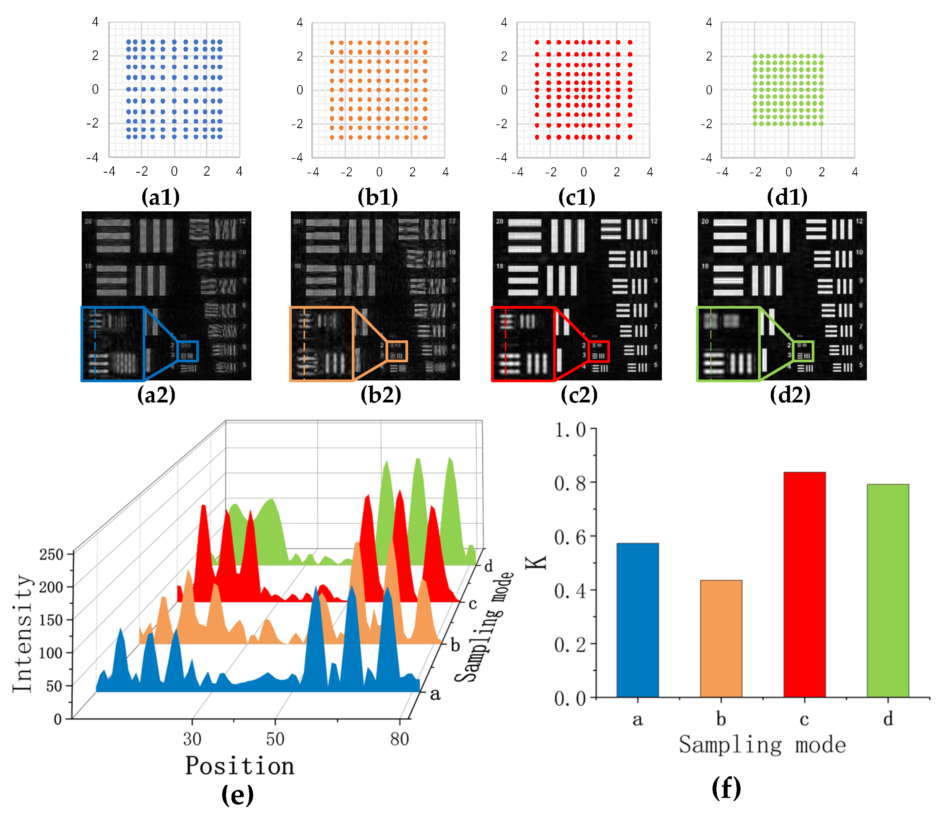
In Figure 2, we take four different sampling approaches in the far-field plane. The number of samples is 121, the aperture size of a single sampling is the same, and the overlap rate is guaranteed to be 60% in the horizontal and vertical directions. Figure 2(a1) is the generally adopted 11 × 11 rectangular array acquisition method. Figure 2(b1) is a diamond collection method, and the collection range is wider on the cross line. Figure 2(c1) adopts cross-line sampling, and distributes more sampling apertures in the high-energy cross-line area. Figure 2(d1) is the comparison experiment of Figure 2(c1). When collecting the high-frequency region, the aperture is allocated to the low-energy region away from the cross-hairs. The result of the final reconstructed image is shown in Figure 2(a2−d2).
Take the intensity distribution of the horizontal stripes at group numbers 2 and 3 with four sampling methods, and the intensity value distribution is shown in Figure 2e. The line pairs per pixel for the two groups of stripes in the original image are 0.250 and 0.167, respectively. The stripes at group 2 in Figure 2(a2) have been indistinguishable, while Figure 2(b2,c2) can be clearly distinguished at group 2 and group 3 with strong contrast. Compared with the original picture, the structural similarity values in the enlarged area of Figure 2(b2,c2) are 0.6302 and 0.6461, respectively, and the value of Figure 2(a2) is 0.5523, which is consistent with the observation. Figure 2(d2) also captures high-frequency region information, but not high-energy regions. This acquisition method results in indistinguishable fringes at group 2 and group 3, with a structural similarity value of only 0.3521. The simulation results show that the sampling method that distributes more apertures in the high-energy region can effectively improve the reconstructed image resolution.

3.2. Non-Uniform Sampling Mode

In addition to using irregular methods, non-uniform sampling methods can also be used. The non-uniform sampling method provides a new idea between sampling range and overlap rate. It also breaks the translational symmetry of sampling and solves the raster grid artefact problem [17]. The non-uniform sampling method expands the spectral sampling range while ensuring the quality of the reconstructed image.
In this way, according to the spectral distribution characteristics, a higher sampling density is used in the area with high energy, and the sampling density is reduced in the area with low energy to achieve the purpose of obtaining more energy information and a larger spectrum range with the same number of samples. Simulate with the same resolution chart as the target image. Figure 3 shows four different sampling modes based on the spectral energy of the target object concentrated in the center area and on the crosshairs. The aperture size of a single sampling is the same, and the number of samples is 121. Figure 3(a1−c1) collected the same size spectrum range. Figure 3(a1) sampling method is that the overlap rate is 58% in the area farthest from the center and the crosshair, and the overlap rate gradually decreases to 30% toward the center and the crosshair area. In Figure 3(b1), the adjacent apertures are uniformly distributed with an overlap rate of 44%. The sampling method of Figure 3(c1) is opposite to that of Figure 3(a1), the overlap rate is 58% in the area close to the center and the crosshair, and the overlap rate gradually decreases to 30% in the area far from the center and the crosshair. In Figure 3(d1), the adjacent apertures are uniformly distributed and the overlap ratio is 60%. The reconstructed images corresponding to several sampling methods are shown in Figure 3(a2−d2).
Compare Figure 3(a2−c2) and the horizontal fringe intensity distributions of group 2 and group 3 (Figure 3e). The 2 and 3 groups of stripes correspond to 0.250 and 0.167 line pairs per pixel in the original image, respectively. When collecting the same spectral range, the image quality of Figure 3(c2) is much better than the other two groups, and the contrast between white and black fringes is more obvious in the intensity distribution. Compared with the original picture, the structural similarity value of Figure 3(c2) at the magnification is 0.5890, Figure 3(a2,b2) are 0.3090 and 0.2339, respectively. Figure 3(a2) has insufficient overlapping rate in the high-energy area, resulting in poor reconstructed image effect, and the overall overlapping rate of Figure 3(b2) is insufficient, resulting in the inability to reconstruct a high-quality image. Figure 3(c2) acquires the same spectral range as Figure 3(a2,b2), but uses a higher overlap rate in the high energy region and a lower overlap rate in the low energy region of the spectrum. This sampling method helps the solution to converge to the global minimum faster, and at the same time expands the sampling range and obtains more high-frequency information. Therefore, it can be seen from the energy distribution map that the resolution of the reconstructed image is higher than that of Figure 3(d2).
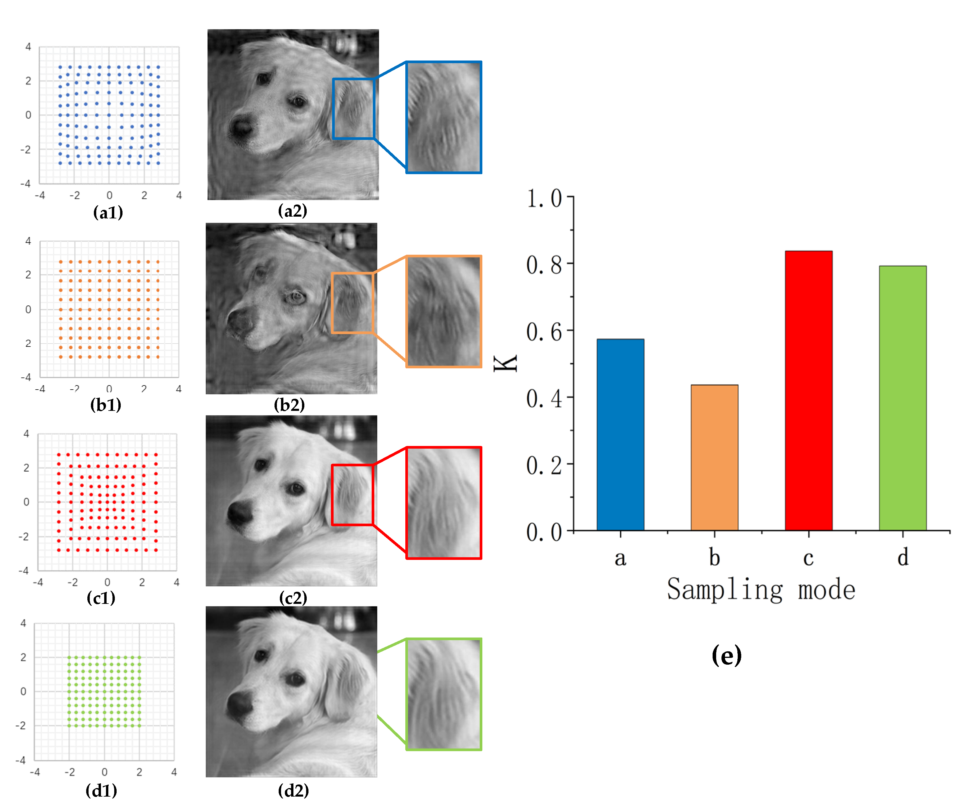
Non-uniform sampling can be applied more to grayscale images. For grayscale images, most of the energy of the spectrum is concentrated in the central low-frequency region, and the energy in the high-frequency region decreases outward. Figure 4 shows four different sampling methods, according to the energy distribution in different regions. The four sampling methods have the same sampling aperture size, and the number of samples is 121. Figure 4(a1−c1) captures the same size spectral range. The sampling method in Figure 4(a1) is low-density sampling in the center of the spectrum, high-density sampling in the surrounding high-frequency regions, and the overlap rate gradually increases from 30% to 58%. Figure 4(b1) shows that the sampling apertures are uniformly arranged, and the adjacent overlap rate is 44%. The sampling method of Figure 4(c1) is opposite to that of Figure 4(a1), the sampling density in the central area is high, the sampling density in the surrounding high-frequency areas is low, and the overlap rate gradually decreases from 58% to 30%. Figure 4(d1) captures a smaller spectrum range than the first three groups. The sampling apertures are uniformly distributed, and the adjacent overlap rate is 60%. The reconstructed image results are shown in Figure 4(a1−d1).
From Figure 4(a2−d2), the overall quality of the reconstructed images in Figure 4(a2,b2) is far worse than Figure 4(c2,d2), and the detailed information is not clearly restored. The overall quality of the images recovered by the latter two sampling methods is high. Compared with the original picture, the structural similarities value in the detail region from Figure 4(a2−d2) are 0.5727, 0.4360, 0.8369, and 0.7921, respectively. Figure 4(c2) restores more image details than other reconstructed images, while ensuring the high quality of the image.
Non-uniform sampling simulations for the resolution chart and grayscale images show that the method of using a higher sampling density in the high-energy region and using a lower sampling density in the low-energy region of the spectrum can ensure the quality of the reconstructed image and increase recovery image resolution.
To sum up, the irregular sampling and non-uniform sampling methods adopt corresponding sampling methods according to the energy distribution of the spectrum. With the same number of samples and the same sampling aperture size, these two methods can restore more image details while ensuring image quality. In the next section, we will conduct experiments to demonstrate the feasibility of irregular sampling and non-uniform sampling in macroscopic Fourier ptychography technology.

4. Experimental Results and Analysis

4.1. Experimental Design

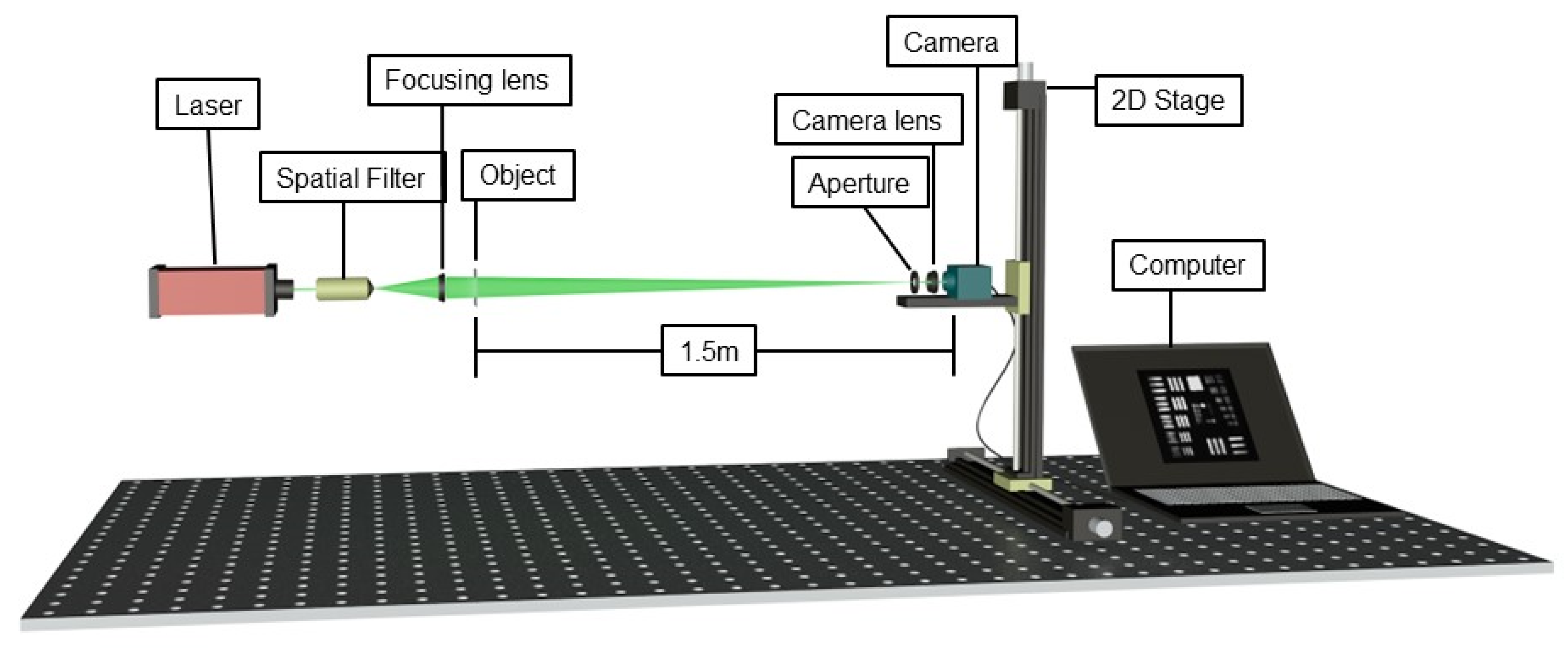
Our imaging system is shown in Figure 5. The system includes a laser with a wavelength of 532 nm, and the laser passes through a spatial filter to ensure the beam quality and spot size. The beam passes through a focusing lens of 150 mm focal length. The object is placed behind the lens to ensure that all parts receive uniform illumination. The object is a hollowed-out United States Air Force (USAF) standard resolution board, the number of line pairs per millimeter ranges from (1–14.25), and the corresponding group numbers are 0, 1, 2, and 3. The group numbers on the resolution board are not hollowed out. The object is placed 1.5 m away from the camera. The light field produces a Fraunhofer diffraction pattern in the aperture plane. The aperture size of the aperture is 2 mm, the lens uses a 12–120 mm zoom lens, and the maximum focal length is used in the experiment. The light field finally intercepted by the diaphragm reaches the camera sensor. The camera is an industrial camera (MER-500-7UM) produced by Fa-vision (Dongguan, China), with a pixel size of 2.2 μm × 2.2 μm. The image data information is transmitted to the computer through the data cable. The high-precision stage moves the camera, aperture, and lens to capture and store images of light fields at different positions. Subsequent experiments used the same system.

4.2. Pre-Sampling

In the previous analysis, the sampling pattern and the sampling aperture distribution should be determined based on the energy distribution. But in actual measurement, we cannot know the spectral energy distribution of the object image in advance. The spectral energy of the image decreases from the center to the surrounding area, and the energy in the low-frequency area of the center is higher, but the energy distribution in the high-frequency area is not clear, and different images show different distributions. Accordingly, we propose a simple strategy to determine the energy distribution of the target image by pre-sampling with a lower overlap rate before formal sampling. Analyze the energy distribution in the spectral range by calculating the intensity sum of the image captured by the camera, and then design the sampling mode. We recorded pictures with a pitch of 0.9 times the aperture size. Here the spectrum is acquired in the range of synthetic aperture ratio 6.4.
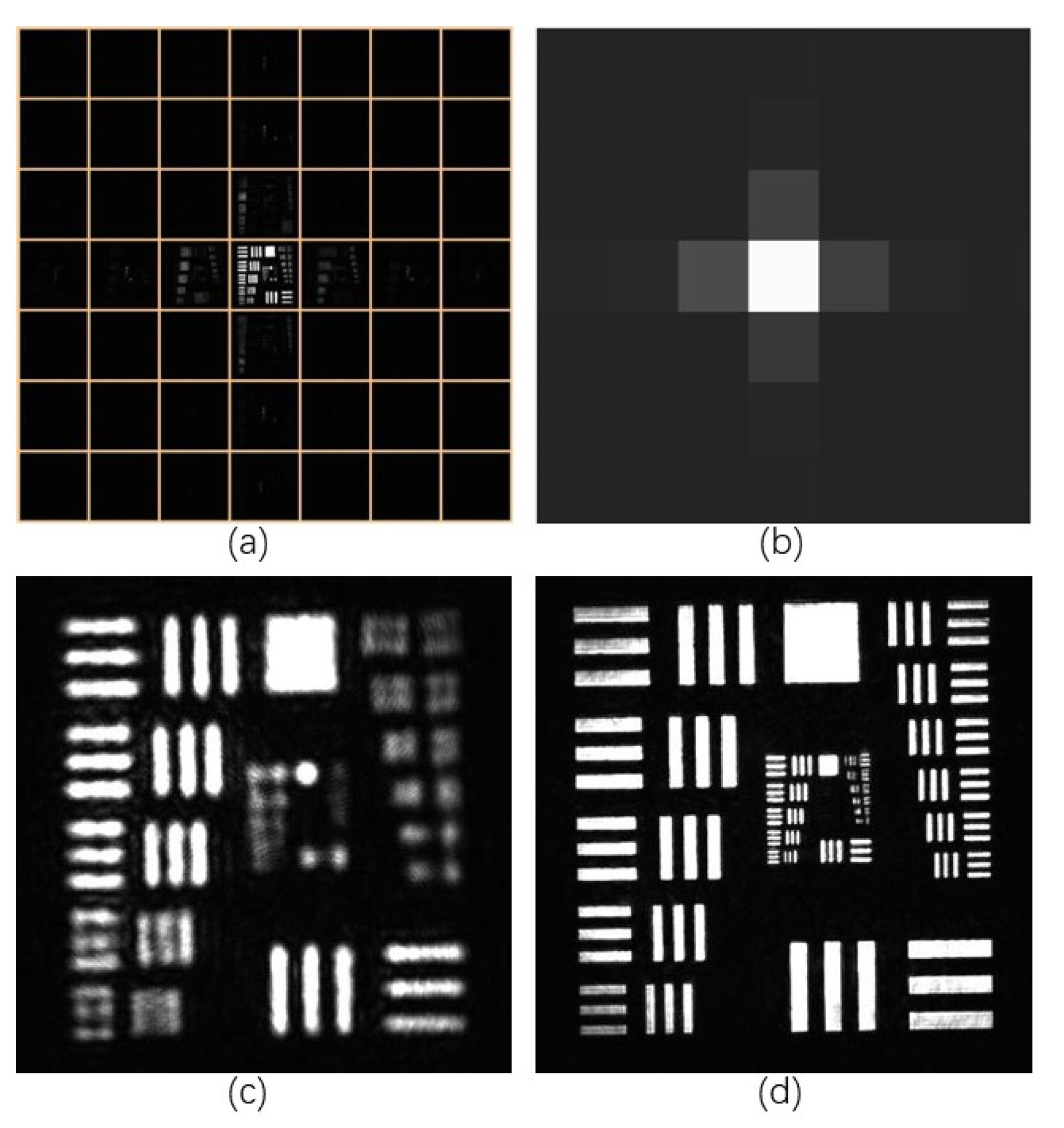
Figure 6a shows the images taken at 49 different positions in the rectangular array and Figure 6b shows the energy intensity of the images taken at the corresponding positions. By the intensity values of images taken at these positions, it can be inferred that the frequency domain energy of the target image is roughly distributed in the central area and the cross-hair area. Based on the energy distribution, we determine the positions of the remaining sampling apertures and discard a portion of the low-energy images that have already been taken. In the next experiment, according to the sampling method proposed in this paper, we selectively retained 33−41 images in the central and cross-hair areas, discarded 8−16 images, and determined the distribution positions of other sampling apertures. Fourier ptychography technology requires a long time in the reconstruction process, and the important factor is the number of images substituted into the restoration algorithm. Although the pre-sampling will sacrifice a small amount of time, it can help us capture images with more information under the approximate number of samples, and reconstruct images with higher resolution within the same recovery time.

4.3. Irregular Sampling Mode

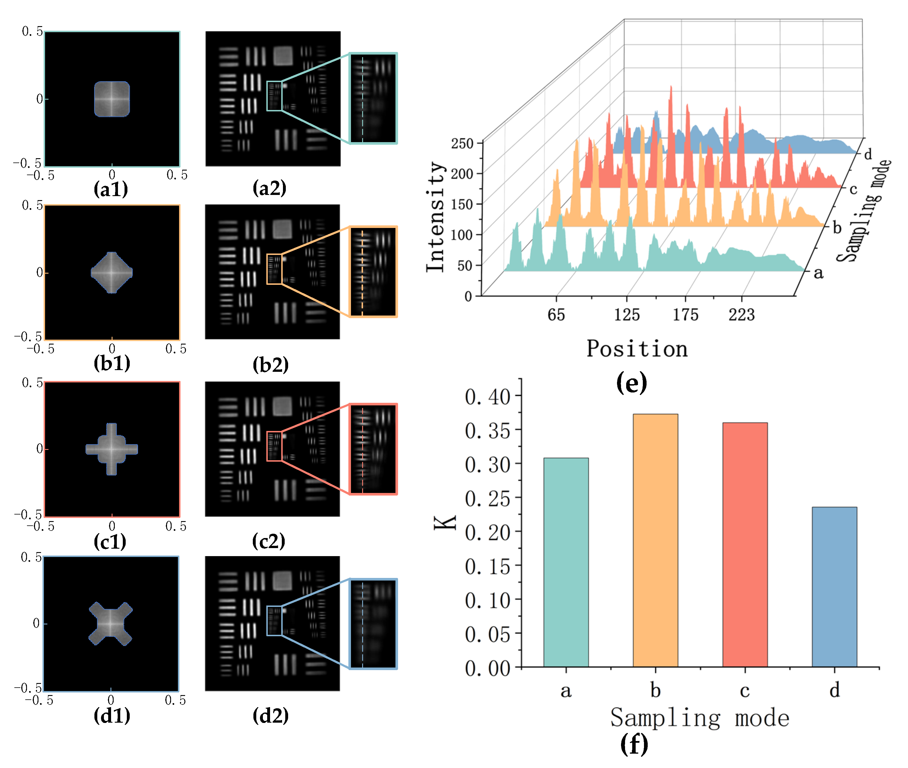
According to the above analysis, we design four different experimental sampling methods, similar to the methods adopted in the simulation experiments. The sampling number is 121, the sampling aperture size is the same, and the overlap rate of adjacent sampling apertures is 70% in the horizontal and vertical directions. The sampling area is shown in Figure 7(a1−d1), and the restored image results are shown in Figure 7(a2−d2).
In Figure 7, we compare four different sampling modes and the vertical intensity of some horizontal stripes (Figure 7e). Figure 7(a2) is an image restored by a general rectangular array sampling method. Figure 7(d2,c2) uses diamond and cross-line sampling methods according to the energy distribution, and the sampling apertures are more distributed in the high-energy cross-line area. Compared with the sampling method of Figure 7(a2), the image at the high frequency information is better recovered. It can be seen from the intensity map that the line pairs that can be resolved are increased from 4.49 lp/mm to 5.66 lp/mm. Both methods increase the resolution of the image. Compared with the image taken with large aperture, the structural similarities value of Figure 7(a2–d2) internal fringes are 0.3079, 0.3727, 0.3599, 0.2355, respectively. Since the experimental sampling range is small, the energy of the sampling area in Figure 7(b1) is slightly higher than that in Figure 7(c1) at the same overlap rate, so the effect of Figure 7(b2) is slightly better than that in Figure 7(c2). The data show that the middle two methods are better for image restoration. The comparison between Figure 7(d2,c2) shows that in the same case of collecting high-frequency areas, collecting high-energy areas are better for image detail recovery.

4.4. Non-Uniform Sampling Mode

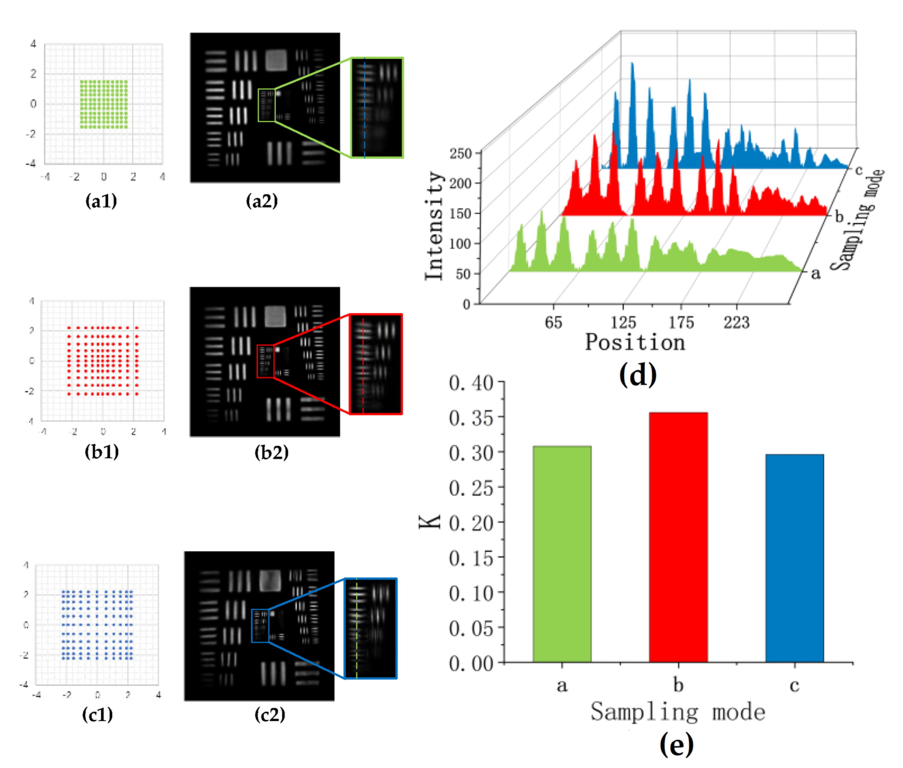
Here we experiment with another sampling mode. We use different sampling densities according to the energy distribution in different regions. The number of samples in the experiment is 121, and the sampling aperture is the same size. Figure 8(a1) is a uniform sampling scheme with 11 × 11 sampling numbers and 70% overlap rate. Figure 8(b1) has an overlap rate of 70% in the center and the crosshairs, which gradually decreases to 42% around the edges. Figure 8(c1) has a 42% overlap in the center and the crosshairs, and gradually increases to 70% around the edges. The images recovered by the three methods are shown in Figure 8.
From the Figure 8, compared with Figure 8(a2), the detail information at high frequency is better recovered in Figure 8(b2), and the spatial resolution is improved from 4.49 lp/mm to 5.04 lp/mm. Compared with the image taken with large aperture, the structural similarities value of Figure 8(a2−c2) internal fringes are 0.3079, 0.3559, 0.2961. Although the sampling method of Figure 8(c2) captures the same size spectrum as Figure 8(b2), the overall image quality is worse than Figure 8(a2,b2). Figure 8(c2) has a high overlap rate in the high frequency part, but the low overlap rate in high energy regions affects the overall reconstruction quality of the image.

5. Discussion and Conclusions

In summary, in the case of using the pre-sampling method to obtain the spectral energy distribution of the target image, we study and analyze two different sampling methods—irregular sampling and non-uniform sampling compared to uniform rectangular array sampling in macroscopic Fourier ptychography technology. These two methods determine the sampling scheme by analyzing the energy distribution in the Fraunhofer diffraction field. In the case of the approximate number of samples and same reconstruction time, we obtain more target image information, expand the sampling range of the spectrum, and improve the resolution of the restored image. Compared with the use of LED lights in microscopic imaging, macroscopic Fourier ptychography technology can be more convenient to implement these two sampling methods. This paper provides more ideas for reducing the number of samples and the overlap rate through subsequent algorithms.

Author Contributions

Conceptualization, Y.W., R.J., and D.S.; methodology, R.J.; software, R.J.; validation, R.J., D.S., and Y.W.; formal analysis, R.J.; investigation, Y.W., R.J., and D.S.; resources, D.S.; data curation, R.J.; writing—original draft preparation, R.J.; writing—review and editing, R.J. and D.S.; visualization, R.J.; supervision, D.S. and Y.W.; project administration, D.S.; funding acquisition, D.S. All authors have read and agreed to the published version of the manuscript.

Funding

Youth Innovation Promotion Association of the Chinese Academy of Sciences (NO. 2020438), Foundation of Key Laboratory of Science and Technology Innovation of Chinese Academy of Sciences (No. CXJJ-20S028).

Institutional Review Board Statement

Not applicable.

Informed Consent Statement

Not applicable.

Data Availability Statement

Not applicable.

Conflicts of Interest

The authors declare no conflict of interest.

References

  1. Zheng, G.; Horstmeyer, R.; Yang, C. Wide-field, high-resolution Fourier ptychographic microscopy. Nat. Photonics 2013, 7, 739–745. [Google Scholar] [CrossRef]
  2. Ryle, M.; Hewish, A. The synthesis of large radio telescopes. Mon. Not. R Astron. Soc. 1960, 120, 220–230. [Google Scholar] [CrossRef]
  3. Bashkansky, M.; Lucke, R.L.; Funk, E.; Rickard, L.; Reintjes, J. Two-dimensional synthetic aperture imaging in the optical domain. Opt. Lett. 2002, 27, 1983–1985. [Google Scholar] [CrossRef]
  4. Miller, N.J.; Dierking, M.P.; Duncan, B.D. Optical sparse aperture imaging. Appl. Opt. 2007, 46, 5933–5943. [Google Scholar] [CrossRef]
  5. Brown, W.M. Synthetic aperture radar. IEEE Trans. Aerosp. Electron. Syst. 1967, 3, 217–229. [Google Scholar] [CrossRef]
  6. Ou, X.; Horstmeyer, R.; Yang, C.; Zheng, G. Quantitative phase imaging via Fourier ptychographic microscopy. Opt. Lett. 2013, 38, 4845–4848. [Google Scholar] [CrossRef]
  7. Tian, L.; Li, X.; Ramchandran, K.; Waller, L. Multiplexed coded illumination for Fourier Ptychography with an LED array microscope. Biomed. Opt. Express 2014, 5, 2376–2389. [Google Scholar] [CrossRef] [PubMed]
  8. Dong, S.; Horstmeyer, R.; Shiradkar, R.; Guo, K.; Ou, X.; Bian, Z.; Xin, H.; Zheng, G. Aperture-scanning Fourier ptychography for 3D refocusing and super-resolution macroscopic imaging. Opt. Express 2014, 22, 13586–13599. [Google Scholar] [CrossRef] [PubMed]
  9. Dong, S.; Shiradkar, R.; Nanda, P.; Zheng, G. Spectral multiplexing and coherent-state decomposition in Fourier ptychographic imaging. Biomed. Opt. Express 2014, 5, 1757–1767. [Google Scholar] [CrossRef]
  10. Memmolo, P.; Bianco, V.; Merola, F.; Miccio, L.; Paturzo, M.; Ferraro, P. Breakthroughs in Photonics 2013, Holographic Imaging. IEEE Photon. J. 2014, 6, 0701106. [Google Scholar] [CrossRef]
  11. Williams, A.J.; Chung, J.; Ou, X.; Zheng, G.; Rawal, S.; Ao, Z.; Datar, R.; Yang, C.; Cote, R.J. Fourier ptychographic microscopy for filtration-based circulating tumor cell enumeration and analysis. J. Biomed. Opt. 2014, 19, 066007. [Google Scholar] [CrossRef] [PubMed]
  12. Zuo, C.; Sun, J.; Li, J.; Asundi, A.; Chen, Q. Wide-field high-resolution 3d microscopy with fourier ptychographic diffraction tomography. Opt. Lasers Eng. 2020, 128, 106003. [Google Scholar] [CrossRef]
  13. Ou, X.; Zheng, G.; Yang, C. Embedded pupil function recovery for Fourier ptychographic microscopy. Opt. Express 2014, 22, 4960–4972. [Google Scholar] [CrossRef]
  14. Dong, S.; Guo, K.; Nanda, P.; Shiradkar, R.; Zheng, G. FPscope: A field-portable high-resolution microscope using a cellphone lens. Biomed. Opt. Express 2014, 5, 3305–3310. [Google Scholar] [CrossRef]
  15. Bian, Z.; Dong, S.; Zheng, G. Adaptive system correction for robust Fourier ptychographic imaging. Opt. Express 2013, 21, 32400–32410. [Google Scholar] [CrossRef]
  16. Horstmeyer, R.; Chen, R.Y.; Ou, X.; Ames, B.; Tropp, J.A.; Yang, C. Solving ptychography with a convex relaxation. New J. Phys. 2015, 17, 1–15. [Google Scholar]
  17. Guo, K.K.; Dong, S.Y.; Nanda, P.; Zheng, G. Optimization of sampling pattern and the design of Fourier ptychographic illuminator. Opt. Express 2015, 23, 6171–6180. [Google Scholar] [CrossRef] [PubMed]
  18. Holloway, J.; Asif, M.S.; Sharma, M.K.; Matsuda, N.; Horstmeyer, R.; Cossairt, O.; Veeraraghavan, A. Toward long distance sub-diffraction imaging using coherent camera arrays. IEEE Trans. Comput. Imaging 2016, 2, 251–265. [Google Scholar] [CrossRef]
  19. Holloway, J.; Wu, Y.; Sharma, M.K.; Cossairt, O.; Veeraraghavan, A. SAVI: Synthetic apertures for long-range, subdiffraction-limited visible imaging using Fourier ptychography. Sci. Adv. 2017, 3, e1602564. [Google Scholar] [CrossRef]
  20. Guzzi, F.; Kourousias, G.; Billè, F.; Pugliese, R.; Gianoncelli, A.; Carrato, S. A parameter refinement method for ptychography based on deep learning concepts. Condens. Matter 2021, 6, 36. [Google Scholar] [CrossRef]
  21. Konda, P.C.; Loetgering, L.; Zhou, K.C.; Xu, S.; Harvey, A.R.; Horstmeyer, R. Fourier ptychography: Current applications and future promises. Opt. Express 2020, 28, 9603–9630. [Google Scholar] [CrossRef] [PubMed]
  22. Donoho, D.L. Compressed sensing. IEEE Trans. Inform. Theory 2006, 52, 1289–1306. [Google Scholar] [CrossRef]
  23. Candes, E.J.; Tao, T. Near-Optimal Signal Recovery from Random Projections: Universal Encoding Strategies? IEEE Trans. Inf. Theory 2006, 52, 5406–5425. [Google Scholar] [CrossRef]
  24. Candes, E.J.; Romberg, J.; Tao, T. Robust uncertainty principles: Exact signal reconstruction from highly incomplete frequency information. IEEE Trans. Inf. Theory 2006, 52, 489–509. [Google Scholar] [CrossRef]
  25. Candès, E.; Romberg, J. Sparsity and incoherence in compressive sampling. Inverse Probl. 2007, 23, 969–985. [Google Scholar] [CrossRef]
  26. Li, Y.; Liu, C.; Li, J.; Wang, Y.; Liu, J. Adaptive and efficient Fourier ptychographic microscopy based on information entropy. J. Opt. 2020, 22, 045702. [Google Scholar] [CrossRef]
  27. Bian, L.; Suo, J.; Situ, G.; Zheng, G.; Chen, F.; Dai, Q. Content adaptive illumination for Fourier ptychography. Opt. Lett. 2014, 39, 6648–6651. [Google Scholar] [CrossRef] [PubMed]
  28. Born, M.; Wolf, E. Principles of Optics: Electromagnetic Theory of Propagation, Interference and Diffraction of Light; CUP Archive: Cambridge, UK, 2000. [Google Scholar]
  29. Gerchberg, R.W. A Practical Algorithm for the Determination of Phase from Image and Diffraction Plane Pictures. Optik 1972, 35, 237. [Google Scholar]
  30. Fienup, J.R. Phase retrieval algorithms: A comparison. Appl. Opt. 1982, 21, 2758–2769. [Google Scholar] [CrossRef]
  31. Fienup, J.R. Reconstruction of a complex-valued object from the modulus of its Fourier transform using a support constraint. J. Opt. Soc. Am. A 1987, 4, 118–123. [Google Scholar] [CrossRef]
  32. Fienup, J.R. Reconstruction of an object from the modulus of its Fourier transform. Opt. Lett. 1978, 3, 27–29. [Google Scholar] [CrossRef] [PubMed]
  33. Fienup, J.R. Lensless coherent imaging by phase retrieval with an illumination pattern constraint. Opt. Express 2006, 14, 498–508. [Google Scholar] [CrossRef] [PubMed]
  34. Tian, L.; Waller, L. 3D intensity and phase imaging from light field measurements in an LED array microscope. Optica 2015, 2, 104–111. [Google Scholar] [CrossRef]
  35. Dong, S.; Bian, Z.; Shiradkar, R.; Zheng, G. Sparsely sampled Fourier ptychography. Opt. Express 2014, 22, 5455–5464. [Google Scholar] [CrossRef] [PubMed]
  36. Wang, Z.; Bovik, A.C.; Sheikh, H.R.; Simoncelli, E.P. Image quality assessment: From error visibility to structural similarity. IEEE Trans. Image Process. 2004, 13, 600–612. [Google Scholar] [CrossRef] [PubMed]
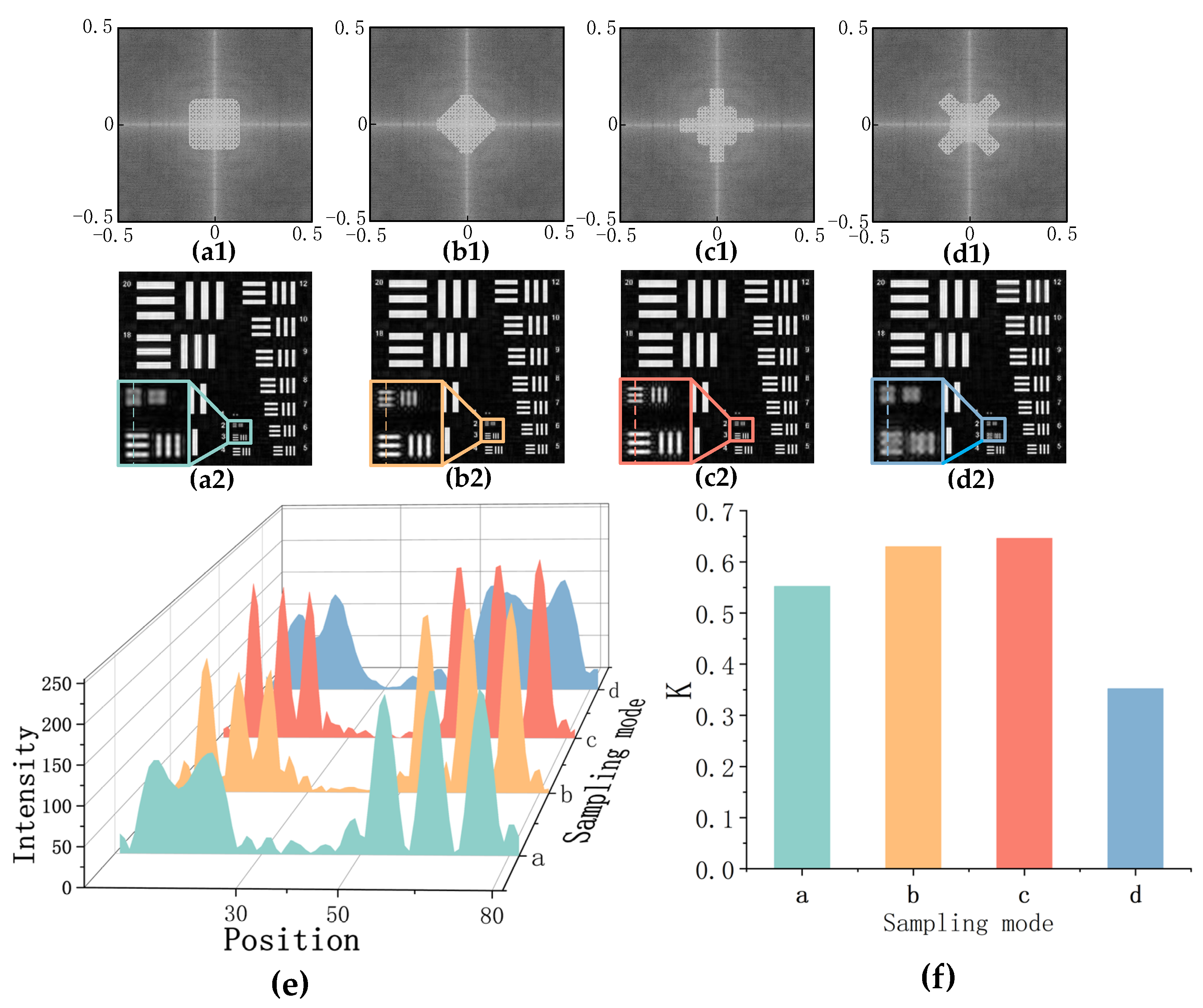
Figure 2. Different sampling modes, reconstruction images and analysis. (a1d1) For different spectral sampling modes, the overlap ratio of adjacent apertures in the horizontal and vertical directions is 60%. (a2d2) Reconstructed images and partial enlarged images corresponding to different sampling modes. (e) Pixel intensity distribution map of the horizontal stripes at group numbers 2 and 3 intercepted at the drawn line. (f) The structural similarity values K corresponding to different reconstructed images.
Photonics 10 00321 g002
Figure 3. Different sampling modes, reconstructed images, and analysis. (a1,c1) Non-uniform sampling, where (a1) has a low overlap rate in the center and cross-hair area, and a high overlap rate away from the center and cross-hair area. (c1) Contrary to (a1), (b1,d1) are uniform sampling modes. (a2d2) are the corresponding image reconstruction results and partial enlarged images. (e) Pixel intensity distribution map of the horizontal stripes at group numbers 2 and 3 intercepted at the drawn line. (f) The structural similarity values K corresponding to different reconstructed images.
Photonics 10 00321 g003
Figure 4. Different sampling modes, reconstructed images and analysis. (a1,c1) are non-uniform sampling, (a1) has a low overlap rate in the central area and a high overlap rate away from the center. (c1) is the opposite of (a1). (b1,d1) are uniform sampling modes. (a2d2) are the corresponding image reconstruction results and partial enlarged images. (e) The structural similarity values K corresponding to different reconstructed images.
Photonics 10 00321 g004
Figure 5. Schematic diagram of the experiment. From left to right: The 532 nm wavelength laser is passed through a spatial filter as a coherent light source. The focusing lens will make the transmitted light field of the object converge on the aperture plane and Fourier transform. The light field passes through an aperture of a certain size, and the lens inverse Fourier transforms the signal and focuses it onto the camera sensor. The electronically controlled high-precision displacement stage drives the camera to capture image information at different positions.
Photonics 10 00321 g005
Figure 6. (a) Images were taken at different positions. (b) Image intensity sum corresponding to (a) position, where the square brightness is proportional to the corresponding image intensity. (c) The image was taken in the central position. (d) The images captured by the large aperture are used as a reference to evaluate the quality of the reconstructed image.
Photonics 10 00321 g006
Figure 7. Experimental sampling mode, imaging results and analysis. (a1d1) Four different experimental sampling areas. The overlap of adjacent apertures is 70% in both the horizontal and vertical directions. (a2d2) Imaging results and enlarged images corresponding to four different sampling modes. (e) The pixel intensity distribution map of the horizontal stripes at group number 2 intercepted at the drawn line. (f) The structural similarity values K corresponding to different reconstructed images.
Photonics 10 00321 g007
Figure 8. Experimental sampling mode, imaging results, and analysis. (a1) Uniform sampling with 70% overlap of adjacent apertures. (b1,c1) Non-uniform sampling. (b1) The overlap rate is low in the central area, and the overlap rate gradually increases toward the surrounding area. (c1) The overlap rate in the center area is high, and the overlap rate gradually decreases toward the surrounding area. (a2c2) The corresponding reconstructed image results and enlarged images. (d) The pixel intensity distribution map of the horizontal stripe at group number 2 intercepted at the drawn line. (e) The structural similarity values K corresponding to different reconstructed images.
Photonics 10 00321 g008
Disclaimer/Publisher’s Note: The statements, opinions and data contained in all publications are solely those of the individual author(s) and contributor(s) and not of MDPI and/or the editor(s). MDPI and/or the editor(s) disclaim responsibility for any injury to people or property resulting from any ideas, methods, instructions or products referred to in the content.