Article

Improving the Resistance of AO-OFDM Signal to Fiber Four-Wave Mixing Effect Based on Insertion Guard Interval

Research Institute of China Telecom Co., Ltd., Beijing 102209, China
*
Author to whom correspondence should be addressed.
Photonics 2023, 10(3), 311; https://doi.org/10.3390/photonics10030311
Submission received: 6 January 2023 / Revised: 9 March 2023 / Accepted: 11 March 2023 / Published: 14 March 2023
(This article belongs to the Section Optical Communication and Network)

Abstract

:
In this paper, a method to suppress the impact of the nonlinear effects on an all optical orthogonal frequency division multiplexing (AO-OFDM) system is proposed. By inserting a guard interval (GI), the duty cycle of the optical signal in each symbol period of each subcarrier is decreased, thus generating a ‘zeroed’ temporal. By giving different time delays to the sub-carriers, these ‘zeroed’ temporals and optical signals of the adjacent sub-carriers are interleaved, which reduces the coincidence of the optical signals between the sub-carriers and eliminates the products of the four-wave mixing (FWM) effect to suppress the influence of the nonlinear effect on the system. The simulation results show that for an AO-OFDM system with 32 subcarriers, inserting GI and introducing different delays for each subcarrier can improve the transmission distance by 30 km or enhance the spectral efficiency by 16.7%, considering the 7% hard decision forward error correction (HD-FEC) threshold. Moreover, even when the number of subcarriers is up to 256 and the power of each subcarrier is as high as 0 dBm, our proposed signal optimization scheme can still guarantee that the BER can satisfy the 7% HD-FEC threshold.

1. Introduction

Orthogonal Frequency Division Multiplexing (OFDM) can provide a flexible next-generation optical transmission network, which can independently manage the allocation of subcarriers for Internet of Things (IoT) applications [1,2,3]. There have been many reports about All Optical Orthogonal Frequency Division Multiplexing (AO-OFDM) systems, which are widely recognized for their high spectrum efficiency and low digital signal processing (DSP) sampling requirements at the receiver side [4,5,6,7,8,9,10,11,12,13]. In short-distance transmission systems, AO-OFDM systems use an Arrayed Waveguide Grating Router (AWGR) [4,5,6,7,8] or Wavelength Selective Switch (WSS) [9,10,11] as the core devices of the Optical Inverse Fourier Transform (OIFT), combined with conventional optical devices, such as Lithium Niobate Modulators and Detectors, which are widely used in optical fiber communications. In recent years, several modified AO-OFDM systems have been reported, such as the Time-Frequency Domain Sparse Subcarrier AO-OFDM system, which can improve the anti-dispersion capability [8]; the Time Interleaved Odd-Even Subcarrier AO-OFDM system, which can reduce the Peak to Average Power Ratio (PAPR) [12]; and the Banded-AO-OFDM system, which can reduce the bandwidth of the receiver [13].
For AO-OFDM systems, one of the main factors that limit their transmission performance is spectrum overlapping. Having a small subcarrier spacing does improve the spectrum efficiency, but it also makes the AO-OFDM signal more susceptible to the influence of large fiber nonlinear noise, such as four-wave mixing (FWM) and cross-phase modulation (XPM). In an AO-OFDM system with a large number of subcarriers, the number of FWM products with the same center frequency as each sub-carrier is huge. For sub-carriers whose center frequency is close to the center frequency of the entire OFDM system, the FWM effect product number is M = 0.375N2, where N is the total number of subcarriers in the system [14]. These FWM products have a huge impact on the AO-OFDM signal, making it too severe to ignore. Yu et al. studied the influence of the noise received during the transmission of optical signals in optical fibers on AO-OFDM signals, and found that FWM is the main factor that reduces the transmission quality of AO-OFDM signals [15].
For long-distance single-carrier and wavelength division multiplexing (WDM) optical fiber communication systems, various nonlinear compensation algorithms have been proposed, such as the split-step Fourier method based on digital back propagation [16,17,18,19,20,21] and the nonlinear compensation method based on neural network technology [22,23,24]. However, these algorithms are designed for single-carrier or WDM systems with large carrier spacing, where the nonlinear distortion mainly comes from SPM and XPM, and are not capable of effectively compensating the nonlinear damage caused by FWM in AO-OFDM systems. Additionally, these methods significantly increase the complexity of the digital signal processing at the receiving end, as well as the cost and delay of signal transmission. Little research has been conducted to reduce the nonlinear impacts of AO-OFDM systems in optical fiber transmission, particularly the reduction in the nonlinear noise generated by the FWM effects. To the best of our knowledge, the AO-OFDM system with a guard interval (GI) inserted has not been widely reported and its benefits have not been carefully studied and analyzed.
In this paper, we propose a scheme that groups and delays the subcarriers of the GI-inserted AO-OFDM system in order to improve its anti-fiber nonlinear ability, particularly its resistance to the FWM effect. The simulation results show that the proposed scheme suppresses the FWM effect and reduces the nonlinear noise generated by the fiber channel. As such, the transmission distance of the AO-OFDM system with 32 subcarriers can be increased from 25 km to 55 km, while still maintaining a BER below a 7% hard decision forward error correction (HD-FEC) threshold. Additionally, under the same FEC decision threshold, the FWM effect is suppressed, allowing for the number of subcarriers to be increased by eight times, while keeping the subcarrier transmission symbol rate unchanged, thus increasing the transmission rate of the whole AO-OFDM system by eight times.

2. Principle

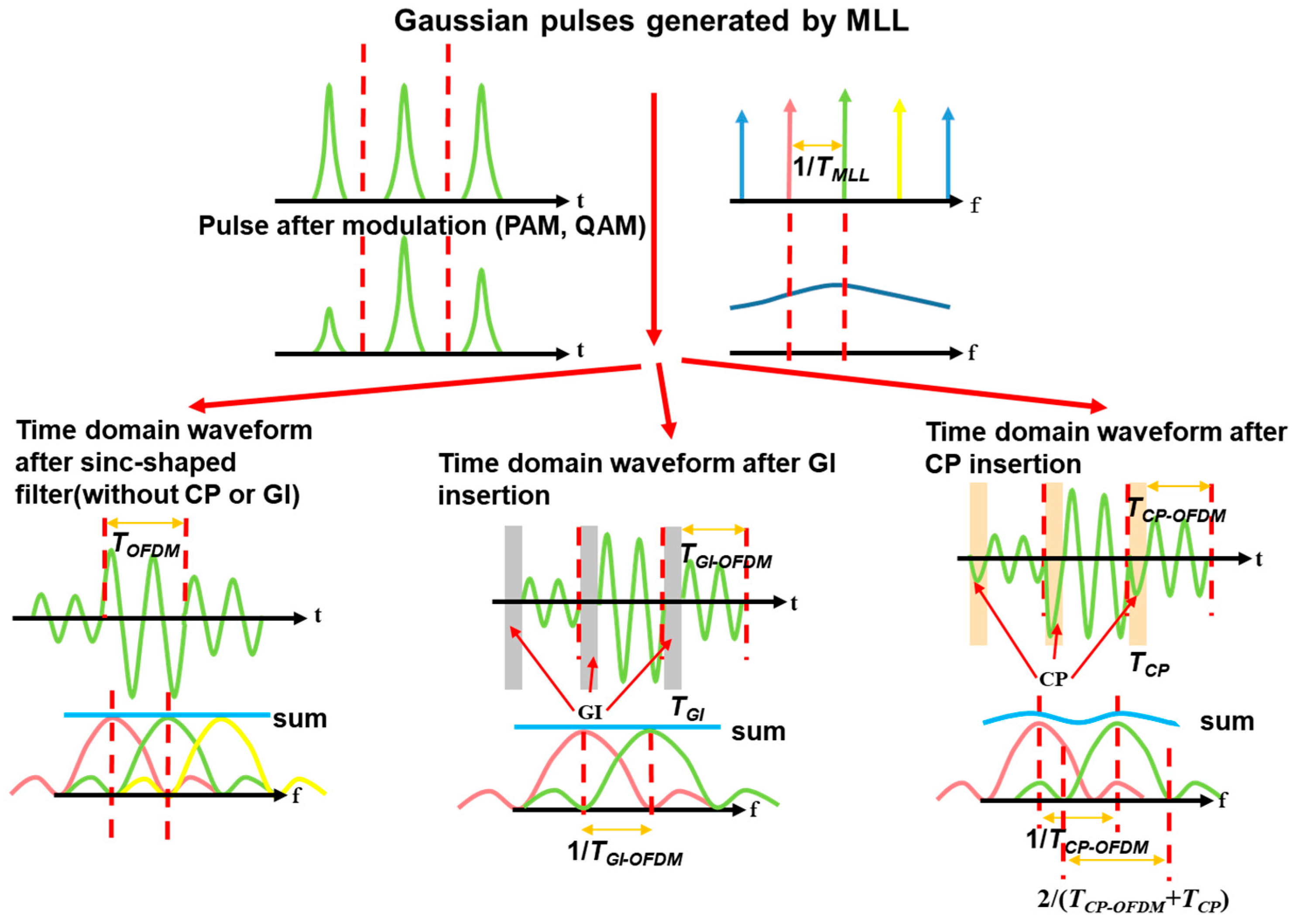
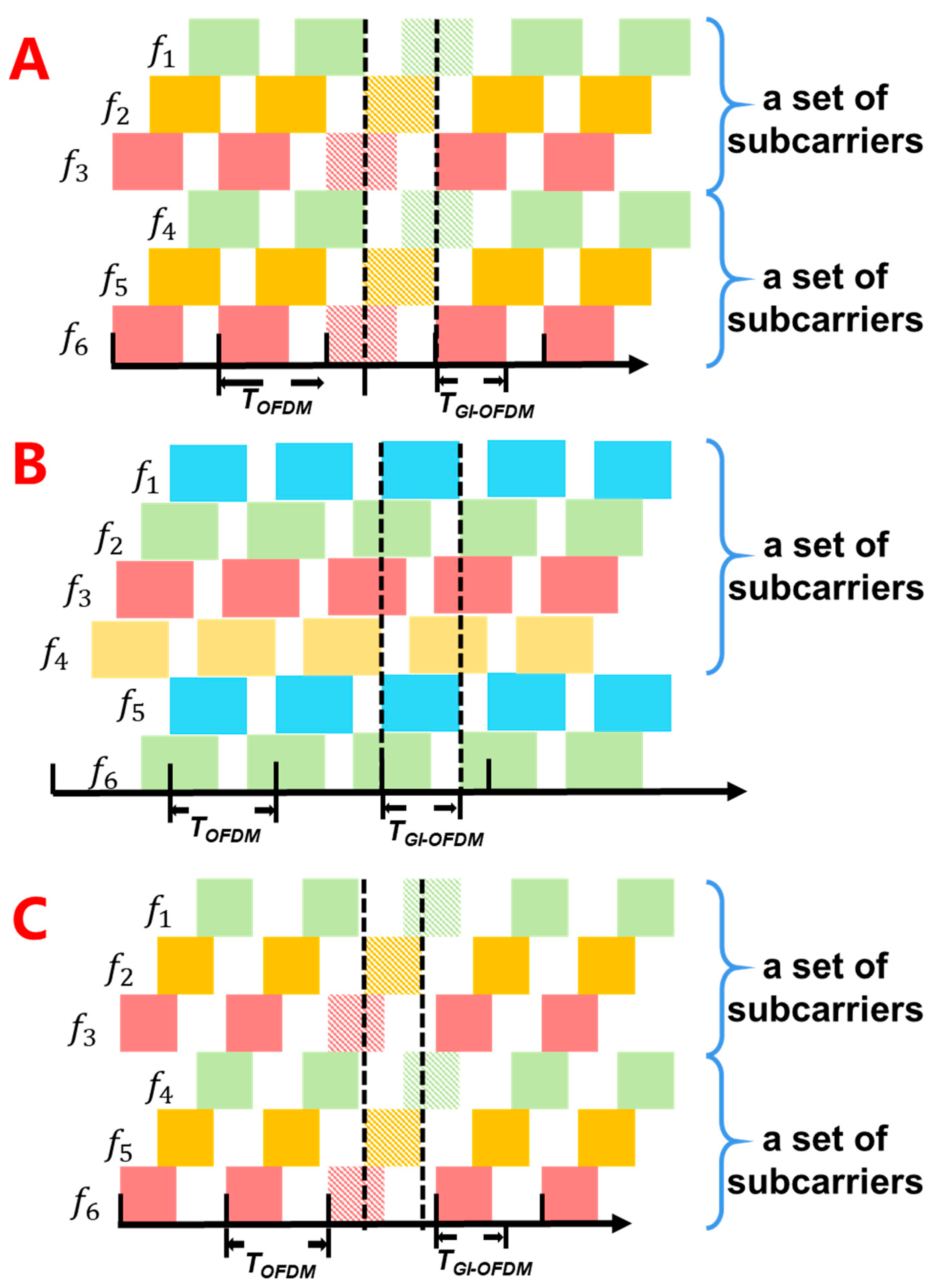
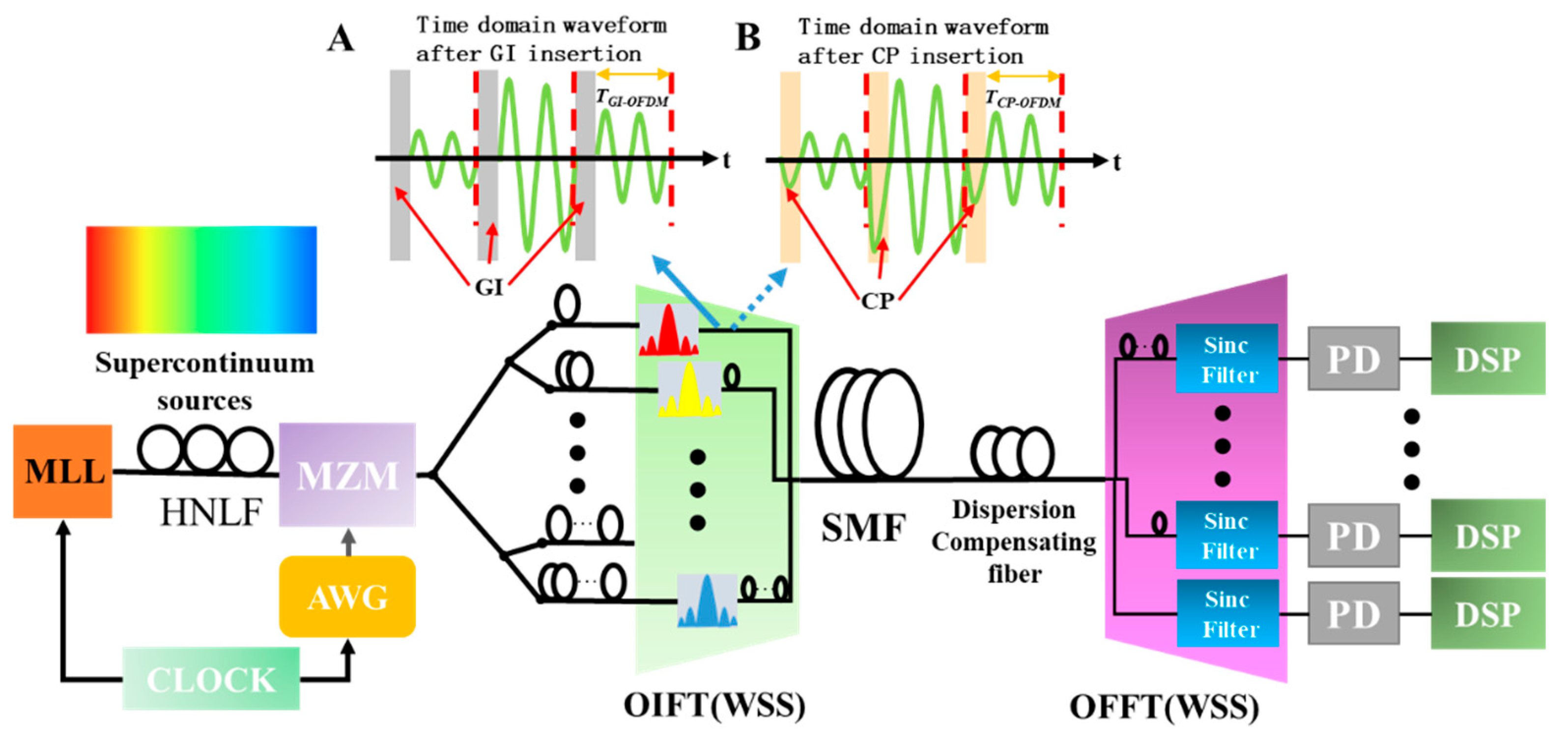
2.1. The AO-OFDM System Inserted GI

When the CP is set to 0.33, the AO-OFDM experiment has achieved a data rate exceeding 26 Tb/s [9]. When the CP is set to 0.1, the AO-OFDM experiment can transmit 875 km through a single-mode fiber with a transmission rate of more than 10 Tb/s [10]. These two representative transmission experiments both improve the stability of the transmission system by reducing the interval of the orthogonal subcarriers. The insertion of a CP in the AWGR [6] and WSS-based AO-OFDM systems [10] has been described in detail, and GI, which can improve the transmission quality of AO-OFDM systems, has also been mentioned in these papers. The performance of the AO-OFDM systems with both CP and GI inserted has been compared [6]. GI is generally considered to be less effective than CP for enhancing the performance of AO-OFDM systems, so it has not been further studied and analyzed. For AWGR-based and WSS-based AO-OFDM systems, it is easy to insert CP and GI. For the AWGR-based AO-OFDM system, the system with GI uses the same design parameters as the AWGR with CP, but the additional waveguide of the CP is removed from the mask layout [6]. For WSS-based AO-OFDM systems, the only difference between inserting a GI and inserting a CP is the bandwidth of the sinc-shaped filter [11]. The bandwidth of the former filter is equal to the interval between the center frequencies of the adjacent filters, while the bandwidth of the latter remains the same as before the CP insertion. For common AO-OFDM systems, especially those based on AWGR and WSS, the best or even only method of inserting a GI is by adjusting the OIFT. This is because each subcarrier is obtained by filtering the modulated supercontinuum spectrum through a sinc-shaped filter, and the optical pulse in each symbol period is usually extremely narrow (around 2 ps). This makes it impossible to insert a GI for optical communication systems by setting the symbol interval of the electrical signal and then modulating it onto the optical carrier, as is conducted in conventional single-carrier or WDM systems. When a GI is inserted into an AO-OFDM system with a CP, the orthogonal subcarriers will change, while the length of each time domain period remains the same, but the duty cycle will change depending on the size of the inserted GI, as shown in Figure 1.
The optical pulse generated by the active mode-locked laser after spectral broadening by a high nonlinear fiber can be approximated as:
s M L L ( t ) = k = 0 N 1 δ k ( t i T O F D M )
After the electrical signal is modulated, it can be expressed as:
u M L L ( t ) = k = 0 N 1 C k i δ k ( t i T O F D M )
where Cki is the ith signal symbol on the kth subcarrier, TOFDM is the symbol period. As illustrated in Figure 1, when the modulated optical pulse signal passes through different sinc-shaped filters, CP or GI insertion can be achieved by changing the bandwidth of the filter and the frequency interval between the adjacent filters. The frequency domain filter functions corresponding to the three pulse shaping functions, which are:
G k ( f ) = s i n c ( f f C O , k f C O )
G k C P ( f ) = s i n c ( f f C P , k f C O )
G k G I ( f ) = s i n c ( f f G I , k f G I )
where f C O = 1 / T O F D M is the corresponding center wavelength without a CP or GI inserted. When inserting a CP or GI, the interval between the sinc-shaped filters increases from fCO to fCP or fGI. For the bandwidth of the filter, when a CP is inserted, it remains fco, while when a GI is inserted, it increases to fGI. The size of the CP and GI is the ratio of TCP or TGI to TOFDM, which is calculated as C P / G I = ( f C P / G I f C O ) / f C P / G I . TCP-OFDM and TGI-OFDM are the duration of the optical signal in each symbol period after the CP/GI is inserted; T C P O F D M / T G I O F D M = ( 1 C P / G I ) T O F D M . fGI-k or fGI-k is the center frequency of the sinc-shaped filter corresponding to the kth orthogonal subcarrier with the filter bandwidth of fGI after inserting a GI or CP.
The same as the AO-OFDM signal after insertion of CP [15], the AO-OFDM signal after the insertion of a GI can be expressed as:
u G I O F D M ( t ) = i = k = 0 N 1 C k i u k ( t i T O F D M )
u k ( t ) = g G I ( t ) e x p [ j 2 π ( k T G I O F D M + f c ) t ]
g G I ( t ) = { 1 ( T G I O F D M ) 0 ( T G I )
where fc is the center frequency of the entire OFDM system, uk(t) and gGI(t) are the waveform and pulse shaping function of the kth subcarrier.
The AO-OFDM system with a GI inserted also maintains the orthogonality between the subcarriers. The AO-OFDM signal with a GI inserted at the receiving end can be represented by the corresponding sinc-shaped filter, as follows:
u o u t ( t ) = u G I O F D M ( t ) h m ( t ) = i = k = 0 N 1 C k i r k ( t i T O F D M )
r k ( t ) = m = 0 N 1 s m k ( t ) exp [ j 2 π ( k T G I O F D M + f ) t ]
H m ( f ) = s i n c ( f f G I m f r )
s k k ( t ) ( m = k ) = { 1 T O F D M ( t T O F D M T r 2 ) ( T O F D M T r 2 t < T O F D M + T r 2 ) T r T O F D M ( T O F D M + T r 2 t < T O F D M T r 2 ) 1 T O F D M ( t + T O F D M + T r 2 ) ( T O F D M T r 2 t < T O F D M + T r 2 ) 0 ( o t h e r )
s m k ( t ) ( m k ) = { exp [ j 2 π ( k m T r ) ( t + T O F D M 2 ) ] exp [ j 2 π ( k m T r ) ( T r 2 ) ] j 2 π ( k m T r ) T O F D M ( T O F D M T r 2 t < T O F D M + T r 2 ) 0 ( T O F D M + T r 2 t < T O F D M T r 2 ) exp [ j 2 π ( k m T r ) T r 2 ] exp [ j 2 π ( k m T r ) ( t T O F D M 2 ) ] j 2 π ( k m T r ) T O F D M ( T O F D M T r 2 t < T O F D M + T r 2 ) 0 ( o t h e r )
where H m ( f ) represents the frequency domain function of the sinc-shaped filter, f G I m represents the center frequency of the mth sinc-shaped filter at the receiving end, and h m ( t ) represents the corresponding time domain function. It is worth noting that the bandwidth f r of the sinc-shaped filter at the receiving end can be adjusted. As a result of the insertion of the GI, f r = 1 / T r within the interval [ f C O , f G I ]   (   T G I O F D M T r T O F D M ) can achieve an error-free reception without noise interference. rk(t) and smk(t) are the waveform and pulse shaping function of the kth subcarrier. When m is equal to k, that is, when the target subcarrier passes through the corresponding sinc-shaped filter with the same center frequency, the pulse shaping function is s k k ( t ) ( m = k ) . The adjacent orthogonal subcarriers will also pass through the filter, and the pulse shaping function is s m k ( t ) ( m k ) after filtering. Combining Equations (12) and (13), we can clearly see that when the AO-OFDM system inserts a GI, there is a flat range for each symbol period after filtering at the receiving end, and the flat range lasts for T O F D M T r = 1 / f C O 1 / f r . The larger the filtering bandwidth of the sinc-shaped filter at the transmitting end, the more GI is inserted. This increases the flat interval in each symbol period, allowing for more sampling time errors, even though it reduces the spectrum utilization rate of the AO-OFDM system. Moreover, due to the small frequency-domain separation of the subcarriers in AO-OFDM, inserting a CP or GI to sacrifice the spectral efficiency still results in the subcarriers being overlapped with each other, leading to a higher spectral efficiency than the WDM systems with other conditions unchanged. In the next section, we analyze the AO-OFDM system that is affected by the nonlinear effects in the presence of walk-off phenomena.

2.2. The FWM Products in AO-OFDM Systems

If the hth subcarrier is used as the reference subcarrier, it can be expressed as [15]:
u ˜ O F D M , h = k = 0 N 1 u ˜ k h ( t , z ) e j [ ( ω k ω h ) t ( β k β h ) z ] , t t β h z
u ˜ k h ( t , z ) contains the leaving relationship between the kth subcarrier and the hth subcarrier. ω k ω h represents the difference between the center angle frequencies of the kth orthogonal subcarrier and the hth orthogonal subcarrier. β k β h represents the difference between the reciprocal of the group velocity of the kth orthogonal subcarrier and the hth orthogonal subcarrier. In addition, in Ref. [15], The Spatio Temporal Complex-Envelope at position z along the fiber and at time t satisfies the nonlinear Schrödinger equation:
u ( z , t ) z + β u ( z , t ) t j β 2 2 u ( z , t ) t 2 + α 2 u ( z , t ) = j γ | u ( z , t ) | 2 u ( z , t )
We substitute the OFDM signal Equation (14) into the NLSE Equation (15) and simplify, yielding a set of coupled mode equations about the hth subcarrier being affected by dispersion and nonlinear effects, equivalently written in our notation as:
u ˜ h z j β h 2 2 u ˜ h t 2 = j β h T u ˜ h j γ [ i , k , l ] s [ h ] u ˜ i h u ˜ k h u ˜ * l h e j Δ β z
s [ h ] = { [ i , k , l ] : ω i + ω k ω l = ω h , i h k } , h = 1 , 2 , , N
β h T = j α 2 + γ [ | u ˜ h | 2 + 2 k = 1 , k h N | u ˜ k h | 2 ]
Δ β = β h 2 ( ω i 2 + ω k 2 ω l 2 ω h 2 )
In agreement with Ref. [17], with the triple summation running over the set s [ h ] of the indexes of frequency triplets corresponding to FWM Intermodulation (intermod) products falling on ω h , namely the set of “proper FWM” intermods, excluding the SPM and XPM “coherent” intermods. α is the loss coefficient, γ is the nonlinear coefficient, β β ( ω ) ω , and β 2 β ( ω ) ω 2 . The Δ β indicates that the frequency conditions of the FWM term affecting the reference subcarrier are satisfied between the subcarriers. The β h T indicates the loss and SPM, the effect of XPM on the nonlinear effect of hth subcarriers. If we only consider the FWM effect and the influence of loss on the AO-OFDM signal and only analyze the product of FWM on the system, Equation (16) can be rewritten as:
u ˜ F W M h z = j γ [ i , k ] s [ h ] u ˜ i h u ˜ k h u ˜ * ( i + k h ) h e j ( Δ β j α ) z
u ˜ F W M h ( z ) = [ i , k ] s [ h ] u ˜ F W M ( N D ) h ( z ) + [ i , k ] s [ h ] u ˜ F W M ( D ) h ( z ) = j γ [ i , k ] s [ h ] u ˜ i h u ˜ k h u ˜ * ( i + k h ) h 1 e α z e j Δ β z j Δ β + α
Finally, for the appreciable loss over the distance z, e α z 1 ; therefore, the product magnitude of the FWM effect directly depends on Δ β . For the hth subcarrier, the FWM product that has the most serious impact on it is generated by the h + 1, h-1th subcarrier and itself, because Δ β is the smallest at this time. The remaining FWM effect products will decrease as Δ β increases; that is, the degree of phase matching decreases. The FWM effect product is divided into two types; one is the non-degenerate FWM effect product u ˜ F W M ( N D ) h , and the other is the degenerate product u ˜ F W M ( D ) h . The degenerate FWM effect product is often considered to have a lower degree of phase matching and a larger Δ β , which has less impact on the system. The non-degenerate FWM effect product u ˜ F W M ( N D ) h ( z ) = j γ u ˜ ( h ± 1 ) h u ˜ ( h 1 ) h u ˜ * ( h ) h 1 e α z e j Δ β z j Δ β + α has the highest degree of phase matching, and its phase matching degree is the highest. For an AO-OFDM system with a small subcarrier spacing, the FWM effect product has the greatest impact on the system. The highest degree of phase matching of the degenerate FWM effect product are u ˜ F W M ( D ) h ( z ) = j γ u ˜ ( h ± 1 ) h u ˜ ( h ± 1 ) h u ˜ * ( h ± 2 ) h 1 e α z e j Δ β z j Δ β + α , and its phase matching degree are also very enormous and higher than most non-degenerate FWM effect products, which cannot be ignored when studying the influence of nonlinear effects on AO-OFDM systems.

2.3. Use GI to Improve the Anti-FWM Effect Ability of AO-OFDM System

As the duty cycle of the AO-OFDM signal has changed after a GI is inserted, we believe that if each subcarrier has a different time delay, the system can be affected and reduced by the nonlinear effects. We can see from Figure 1 that after a GI is inserted, a part of each symbol period of each orthogonal subcarrier has no optical signal or the intensity is 0. When the inserted GI = 1/M (M is an integer greater than 3), all M adjacent orthogonal subcarriers are divided into a group; the first subcarrier of each group is not delayed, the second subcarrier is delayed by G I × T O F D M , and the third is delayed by 2 G I × T O F D M , the Mth subcarrier delay ( M 1 ) G I × T O F D M . When M is a positive number less than 3 and greater than 1, the subcarrier can be grouped according to GI = 1/3(M = 3) and the delay can be performed. In this way, the GI and the optical signal can be staggered under the condition that the minimum time delay is given to each sub-carrier, so that all orthogonal sub-carriers have the lowest degree of overlap.
When inserted with a GI size of 1/3, the optical signal lasts 2/3 period in the symbol period, and the FWM products, whether degenerate or non-degenerate, are divided into three categories, when the 4th subcarrier in Figure 2A with a central frequency of f4 is used as the object of study:
The first category is because the three subcarriers are inserted with a GI and given different sizes of delays u ˜ ( 3 ) 4 u ˜ ( 5 ) 4 u ˜ * ( 4 ) 4 = 0 at (h = 4, i = 3, k = 5) (non-degenerate) or (h = 4, i = 2, k = 3) u ˜ ( 3 ) 4 u ˜ ( 2 ) 4 u ˜ * ( 1 ) 4 = 0 (non-degenerate). When u ˜ ( h + i ) h u ˜ ( h + k ) h u ˜ * ( h i k ) h = 0 the FWM product intensity u ˜ F W M 4 ( z ) = j γ u ˜ i h u ˜ k h u ˜ * ( i + k h ) h 1 e α z e j Δ β z j Δ β + α = 0 .
The second category is u ˜ ( 2 ) 4 u ˜ ( 5 ) 4 u ˜ * ( 3 ) 4 0 at (h = 4, i = 2, k = 5) (non-degenerate) or (h = 4, i = 2, k = 3) u ˜ ( 3 ) 4 u ˜ ( 3 ) 4 u ˜ * ( 2 ) 4 0 (degenerate). However, the FWM products calculated in Equation (18) have a duration of 1/3 sign period and falls within the GI of the 4th subcarrier, which has a small effect on the non-GI optical signal part of the 4th subcarrier.
The 3rd category is u ˜ ( 1 ) 4 u ˜ ( 7 ) 4 u ˜ * ( 4 ) 4 0 at (h = 4, i = 1, k = 7). The duration of the FWM effect products in each symbol period is 2/3 of the symbol period that coincides with the optical signal in time, and the AO-OFDM system is still affected by this type of FWM product, but the number of FWM effect products that meet this condition drops to 1/3 of the time when a GI is not inserted, and the 3rd type of FWM effect products have a smaller intensity because of the larger phase mismatch factor. Therefore, compared with the conventional AO-OFDM system, the scheme proposed in this section can greatly reduce the impact of the FWM effect on the system.
When M > 3, such as GI = ¼, shown in Figure 2B, the delay of the subcarriers will still alleviate the influence of the FWM effect on the AO-OFDM signal to a certain extent, such as u ˜ ( 5 ) 4 u ˜ ( 3 ) 4 u ˜ * ( 4 ) 4 0 (h = 4, i = 3, k = 5) (non-degenerate); the FWM products calculated in Equation (18) have a duration of 1/4 sign period and falls within the GI of the 4th subcarrier, which has a small effect on the non-GI optical signal part of the 4th subcarrier.
When M is a positive number less than 3 and greater than 1, such as GI = 2/5, shown in Figure 2C, the subcarrier can be divided into three groups according to GI = 1/3, the corresponding delay is given, the FWM products will also have three situations when GI = 1/3, and the negative impact of the FWM effect on the AO-OFDM signal is alleviated.
Although the FWM effect is more suppressed after the subcarriers of the AO-OFDM system with GI = 0.5 are grouped and delayed, the interval between the subcarriers is already twice that of the GI/CP without the insertion. Under this parameter setting, the spectral efficiency advantage of AO-OFDM compared with DWDM will no longer exist. Therefore, we believe that, according to the existing report on the large-capacity transmission of the AO-OFDM system, it is appropriate to insert GI = 0.33. In the next section, we will verify our proposed FWM effect mitigation scheme through simulation.

3. Simulation and Results

Figure 3 shows the simulation setup of the AO-OFDM system. An optical frequency comb with 10 GHz spacing is generated by a mode-locked laser (MLL) and then broadened in a 300 m dispersion-flattened highly nonlinear fiber (DF-HNLF). The modulated optical pulses are then filtered to form orthogonal subcarriers with different center frequencies. After delaying for different GIs, these subcarriers combine to form a complete AO-OFDM signal. By controlling the filter bandwidth of these sinc-shaped filters and the frequency spacing between them, different sizes of GI or CP are inserted. In order to facilitate the analysis, the traditional AO-OFDM system with a CP inserted is called C-AO-OFDM, and the AO-OFDM system with a GI inserted, grouped, and delayed is called G-AO-OFDM. The key parameters in the simulation are shown in Table 1. Regardless of the interval between the CP/GI filters inserted being 10/(1-CP/GI) GHz, the filter bandwidth is 10/(1-CP/GI) GHz when a GI is inserted, and the filter bandwidth is 10 GHz when a CP is inserted. The symbol rate of the four-pulse amplitude modulation (PAM4) signals carried by the subcarriers is 10 Gbaud with a sequence length of 219−1. When the iterative split-step Fourier method is used to simulate the transmission of the optical signals in the optical fiber, each symbol period is sampled 128 times, the step length is 100 m, and each iteration has five individual steps. When considering the nonlinear effects, SPM, XPM and FWM are analyzed together, and in order to simulate closer to the actual situation, white noise less than 20dB of the optical signal is added to simulate the ASE introduced by other devices, such as arbitrary waveform generators and modulators.
After SMF transmission, the dispersion compensation fiber (DCF) is used to compensate the dispersion of the AO-OFDM signal. The length of the SMF is ten times that of the DCF, which subjects the optical signal to the same cumulative dispersion in absolute values after transmission through both fibers. The filter used to separate the subcarriers at the receiving end is a sinc-shaped filter, and the bandwidth is 15 GHz (GI = 0.33) or 12.5 GHz (GI = 0.2) for G-AO-OFDM; the bandwidth is 10 GHz for C-AO-OFDM. The center frequency of each filter is the same as the filter corresponding to the transmitting end. The signal undergoes clock synchronization and signal demodulation after being converted from an optical signal to an electrical signal by the PD. The electrical signal converted by the PD is synchronized by the DSP and the extra time delay added to different subcarriers at the transmitting terminal is removed. The digital back propagation (DBP) in Ref. [16] was used for the nonlinear compensation of the AO-OFDM systems inserted into a CP as the control groups for the simulation analysis.

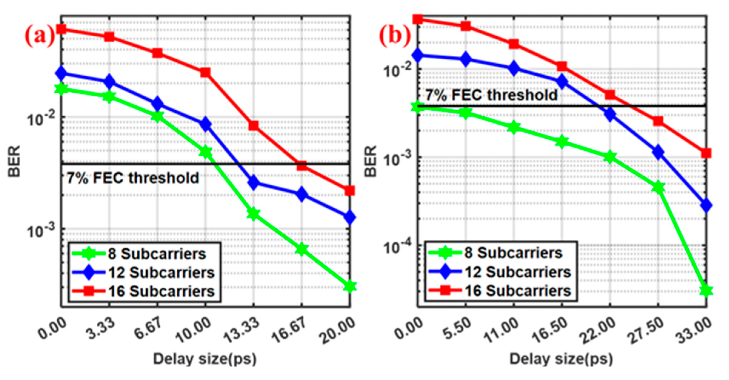
3.1. Effect of Delay on Anti-FWM Effect of AO-OFDM Signal after GI Insertion

Figure 4 show the BER of the AO-OFDM signals with 8, 12, and 16 subcarriers after the 80 km transmission in SMF. The launched power of each orthogonal subcarrier in the system is 4 dBm. From Figure 4B, we can see that the closer the time delay between subcarriers is to GI×TOFDM = 33 ps, the lower the BER of the AO-OFDM system. We did not discuss the case where the delay difference between subcarriers exceeds GI×TOFDM, because after the GI is inserted, the degree of the overlap of the modulated signals of each orthogonal subcarrier will decrease with the delay difference between the subcarriers until the delay difference is equal to GI×TOFDM. After that, the degree of overlap will increase until the time delay is equal to the TOFDM, and the modulated signals between each subcarrier completely overlap, which is equivalent to no time delay. From Figure 4, we can see that as the delay difference between the subcarriers increases, the degree of coincidence between the subcarriers decreases. When the delay difference is GI×TOFDM, the degree of coincidence is the lowest. For the G-AO-OFDM with GI = 0.33 and 16 subcarriers with a power of 4 dBm per subcarrier, BER = 0.0367 when the time delay is 0, and BER = 0.0011 when the time delay is GI×TOFDM. For the G-AO-OFDM with GI = 0.2 and 16 subcarriers with a power of 4 dBm per subcarrier, BER = 0.0610 when the time delay is 0, and BER = 0.00219 when the time delay is GI×TOFDM. As the degree of coincidence between the subcarriers is reduced, the impact of the XPM and FWM effects on the system is also reduced, and the reduction in BER is more significant when GI = 1/3. In addition, whether the inserted value is 1/5 or equal to 1/3, the nonlinear effect of the system can be suppressed due to the appropriate time delay between the carriers, even if a smaller GI is inserted to ensure the spectrum utilization of the system. Although the subcarriers of the G-AO-OFDM system will have a GI×TOFDM size delay due to the walk-off phenomenon at a certain moment, the nonlinear effect has already had a greater impact on the optical signal when the optical signal power is strong. When the walk-off phenomenon is not significant, the BER of the system is much higher than that of the G-AO-OFDM system because of the higher power and more nonlinear noise.

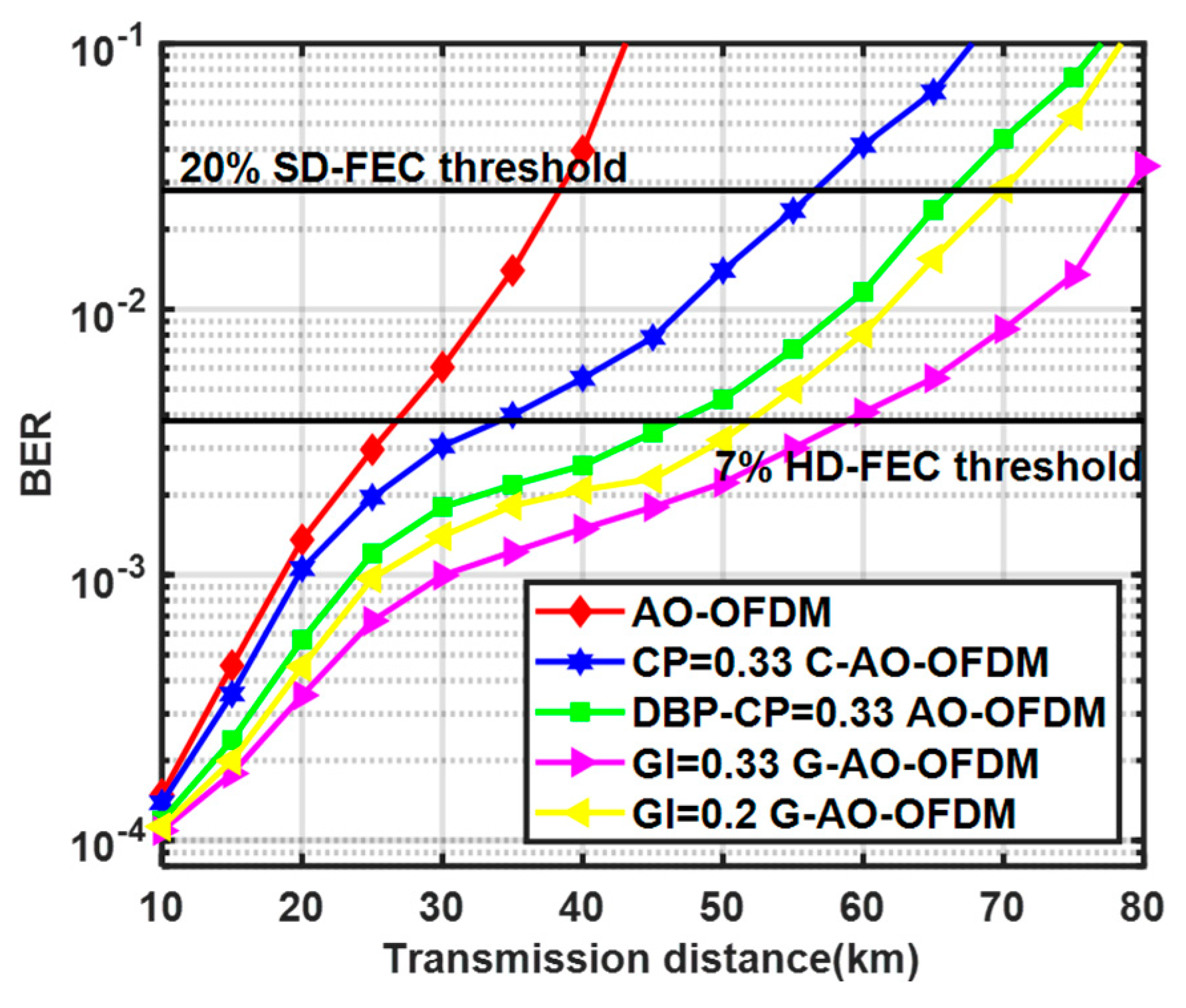
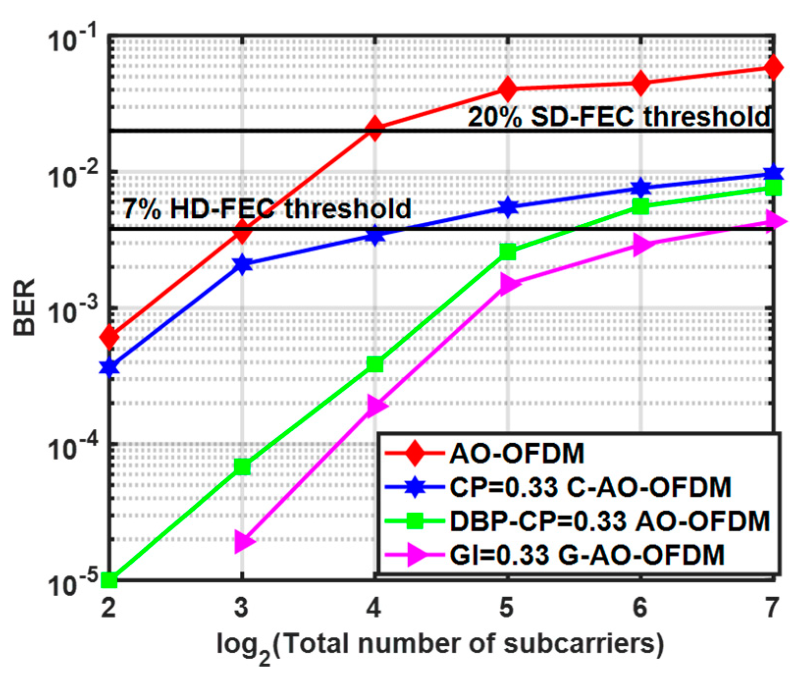
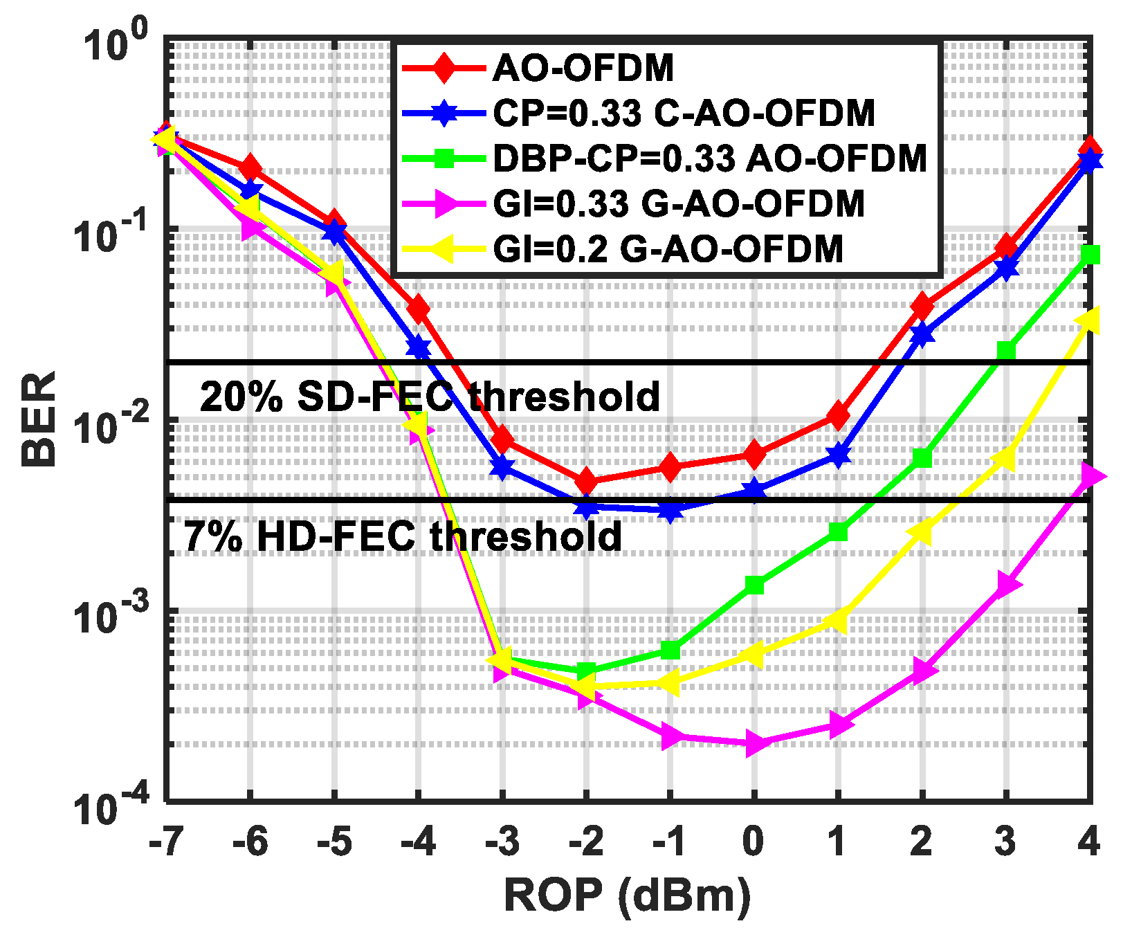
3.2. Comparison of Multiple FWM Effect Suppression Methods under Different Transmission Conditions

Figure 5 shows the BER of the AO-OFDM signal with 32 subcarriers after using different FWM effect suppression methods. The red curve represents the AO-OFDM system without any improvement of the FWM effect suppression method the blue curve represents the AO-OFDM system after inserting a CP of size 1/3; the green curve represents the AO-OFDM system after inserting a CP of size 1/3 and performing DBP at the receiving end; and the yellow and magenta curves represent a system that inserts a GI of size 1/5 and 1/3 and assigns a delay to the subcarrier, respectively. Comparing the red, blue, and magenta curves, it can be found that after inserting a GI with a size of 1/3 and applying an accurate delay to the subcarrier, the anti-FWM ability of the AO-OFDM has been greatly improved. The AO-OFDM system without any improvement has exceeded the 7% HD-FEC and 20% SD-FEC thresholds after the 30 km and 40 km SMF transmissions, and after inserting a GI of 1/3 size and properly delaying the subcarrier, it can be below the above two FEC thresholds after the 55 km and 75 km SMF transmissions. From the blue and magenta curves, when there is the same adjacent subcarrier frequency interval, with 7% HD-FEC and 20% SD-FEC as the threshold, the transmission distance of the system inserted into the GI can be increased by 20 km. Even if DBP is used to compensate for the fiber nonlinear effects, our proposed method can still obtain a transmission distance gain of 10 km. At the same time, even if a 1/5 size GI is inserted (adjacent subcarrier centers spaced at 12.5 GHz), the subcarrier interval in the system is smaller than that inserted into a 1/3 size CP system (adjacent subcarrier centers spaced at 15 GHz), and it obtains a lower BER after a SMF transmission of more than 15 km. In other words, at the same transmission distance, the spectral efficiency of the AO-OFDM system can be improved by 16.7% through the use of the insertion GI and delaying the subcarrier. The simulation results, shown in Figure 5, show that the proposed method can increase the transmission distance of the AO-OFDM with the same spectrum utilization, and at the same time, can achieve a lower BER for AO-OFDM systems with higher spectrum utilization. In addition, with the increase in the transmission distance, the AO-OFDM system inserted into a GI has a lower BER than the traditional AO-OFDM and the system using the DBP algorithm, and the BER gap transmission distance increases. This also shows that as the transmission distance increases, the stronger the nonlinear effect, the more obvious the suppression effect of the proposed method on the FWM effect.
Figure 6 shows the BER of AO-OFDM systems with different subcarrier numbers after using different FWM effect suppression methods. It is clear from Figure 6 that the BER of an AO-OFDM system without FWM effect suppression has exceeded the 20% SD-FEC threshold when the number of subcarriers is 16, and after using our proposed method, the AO-OFDM with the number of subcarriers increased to 128 can still obtain a BER well below the 20% SD-FEC threshold, and even the system with 64 subcarriers can still obtain a BER below the 7% HD-FEC threshold. With the same spectrum utilization, our proposed method can also at least double the subcarrier compared to the blue, green, and magenta curves, with the BER below the 7% HD-FEC threshold. The AO-OFDM system inserted into a CP still has a higher bit error rate than that of a system that inserts a GI and delays the subcarrier when the DBP algorithm is used to increase the complexity of the algorithm at the receiving end. The simulation results in Figure 6 show that the proposed scheme can increase the number of subcarriers of the AO-OFDM system under the same transmission conditions and reduce the negative effects caused by the increase in subcarriers of the AO-OFDM system.
Figure 7 shows the change of the BER with the ROP for five AO-OFDM systems with 16 subcarriers. From the trend of the five curves, the five AO-OFDM systems all obtained the lowest BER, from −2 dBm to 0 dBm. In the range of −7 dBm and −3 dBm for each subcarrier, the FWM effect is not a major factor in the bit errors, and the BER decreases as the ROP increases. With the increase in the ROP, in the range of 0 dBm and 4 dBm, the nonlinear effect of the optical fiber gradually becomes a key factor affecting the transmission quality of the system. With the same spectrum utilization, an AO-OFDM system with GI insertion and subcarrier delay below the 7% HD-FEC threshold has a ROP range of −3 dBm and 3 dBm, while an AO-OFDM system with CP has a ROP range of −1 dBm and 0 dBm. Although the AO-OFDM system with the same size CP inserted after using DBP is very close to the AO-OFDM system using our proposed method in the ROP range of −7 dBm and −3 dBm, in the range of −2 dBm and 4 dBm, our proposed method can obtain a lower BER. From the simulation results in Figure 7, although the FWM suppression method proposed by us does not significantly reduce the ROP required for the AO-OFDM system to reach the 7% HD-FEC threshold or 20% SD-FEC threshold, it can obtain a lower BER under the same transmission conditions.
Figure 5, Figure 6 and Figure 7 shows the changes of the BER in the AO-OFDM systems using different methods and under different transmission distances, subcarrier number changes, and ROP differences, which show that as the system receives stronger nonlinear effects, the AO-OFDM system with a GI inserted has a lower BER than the traditional AO-OFDM and the system using the DBP algorithm, and the BER gap increases with the enhancement of the nonlinear effect. This also shows that the stronger the nonlinear effect, the more obvious the suppression effect of the proposed method on the FWM effect.

4. Future Works

In this paper, we propose a method to reduce the strength of the FWM effector product by inserting a GI and grouping the delay of the subcarrier to improve the anti-FWM effect ability of the AO-OFDM system. The oversimulation verifies that the AO-OFDM system with a GI inserted has higher resistance to the FWM effect from the perspectives of the different ROP, different number of subcarriers, and different transmission distances. In the following work, we will verify our proposed method experimentally and analyze the impact of FWM effects on the system under different modulation formats. When the AO-OFDM system contains more subcarriers, the noise generated by the XPM effect is also a key factor affecting the transmission quality of the system, and the XPM effect may replace the FWM effect when the center frequency interval of the subcarrier is large, which is the main factor affecting the transmission quality of the AO-OFDM system. Studying how to reduce the impact of the XPM effect on the system is also something we want to do in the future.

5. Conclusions

In this paper, a method is proposed to insert a GI and delay each subcarrier in the AO-OFDM system to suppress the FWM effect. After introducing the insertion method of a GI, the generation mechanism of the FWM products and the principle of FWM suppression based on Gi insertion, we prove through simulation results that the method proposed by inserting AO-OFDM signals into a GI and grouping the delay can greatly suppress the influence of the FWM effect on the transmission quality of the AO-OFDM system. The simulation results show that the AO-OFDM system with 32 subcarriers inserted in a GI and a delayed subcarrier can increase the transmission distance by 30 km or improve the spectrum utilization by 16.7% under the condition that the BER is less than the 7% HD-FEC threshold. At the same time, under the BER requirement below the same FEC decision threshold, the AO-OFDM system is suppressed due to the FWM effect, and the subcarrier can be increased by eight times under the premise that the subcarrier transmission symbol rate remains unchanged; that is, the transmission rate of the whole AO-OFDM system increased by eight times. Inserting a GI and accurately delaying the subcarrier can greatly reduce the strength of the FWM products and inhibit the influence of the FWM effect on the transmission quality of the AO-OFDM system, and this optical fiber nonlinear effect suppression method does not increase the algorithm complexity of DSP at the sending or receiving part of the system, and can further develop the AO-OFDM system.

Author Contributions

Conceptualization K.L., H.L. and X.S.; methodology, A.Z. and H.L.; software, L.F.; validation, X.S.; formal analysis, Y.L.; investigation, J.L.; resources, X.H.; data curation, J.L.; writing—original draft preparation, J.L.; writing—review and editing, K.L.; visualization, K.L.; supervision, K.L.; project administration, K.L.;. All authors have read and agreed to the published version of the manuscript.

Funding

There is no funding for this work.

Institutional Review Board Statement

Not applicable.

Informed Consent Statement

Not applicable.

Data Availability Statement

The data underlying the results presented in this paper are not publicly available at this time but may be obtained from the authors upon reasonable request.

Conflicts of Interest

The authors declare no conflict of interest.

References

  1. William, S.; Bao, H.; Tang, Y. Coherent optical OFDM: Theory and design. Opt. Express 2008, 16, 841–859. [Google Scholar]
  2. Konstantinos, C.; Tomkos, I.; Varvarigos, E. Elastic bandwidth allocation in flexible OFDM-based optical networks. J. Lightw. Technol. 2011, 29, 1354–1366. [Google Scholar]
  3. Moreolo, M.; Fabrega, J.; Nadal, L.; Vílchez, F.; Mayoral, A.; Vilalta, R.; Muñoz, R.; Casellas, R.; Martínez, R.; Nishihara, M.; et al. SDN-enabled sliceable BVT based on multicarrier technology for multiflow rate/distance and grid adaptation. J. Lightw. Technol. 2016, 34, 1516–1522. [Google Scholar] [CrossRef] [Green Version]
  4. Lowery, A.J.; Du, L. All-optical OFDM transmitter design using AWGRs and low-bandwidth modulators. Opt. Express 2011, 19, 15696–15704. [Google Scholar] [CrossRef] [PubMed]
  5. Wang, Z.; Kravtsov, K.S.; Huang, Y.; Prucnal, P.R. Optical FFT/IFFT circuit realization using arrayed waveguide gratings and the applications in all-optical OFDM system. Opt. Express 2011, 19, 4501–4512. [Google Scholar] [CrossRef]
  6. Lowery, A.J. Inserting a cyclic prefix using arrayed-waveguide grating routers in all-optical OFDM transmitters. Opt. Express 2012, 20, 9742–9754. [Google Scholar] [CrossRef]
  7. Shimizu, S.; Cincotti, G.; Wada, N. Demonstration and performance investigation of all-optical OFDM systems based on arrayed waveguide gratings. Opt. Express 2012, 20, B525–B534. [Google Scholar] [CrossRef]
  8. Kodama, T.; Miyazaki, T.; Hanawa, M.; Maruta, A.; Wada, N.; Cincotti, G. Low-speed DSP assisted dispersion compensation-free IM/DD optical OFDM transmission over 100 km-SMF using time-and frequency-domain sparse-subcarrier multiplexing. In Proceedings of the 2019 Optical Fiber Communications Conference and Exhibition (OFC), San Diego, CA, USA, 3–7 March 2019; pp. 1–3. [Google Scholar]
  9. Hillerkuss, D.; Schmogrow, R.; Schellinger, T.; Jordan, M.; Winter, M.; Huber, G.; Vallaitis, T.; Bonk, R.; Kleinow, P.; Frey, F.; et al. 26 Tbit s−1 line-rate super-channel transmission utilizing all-optical fast Fourier transform processing. Nat. Photon. 2011, 5, 364–371. [Google Scholar] [CrossRef]
  10. Schröder, J.; Du, L.; Carpenter, J.; Eggleton, B.; Lowery, A. All-optical OFDM with cyclic prefix insertion using flexible wavelength selective switch optical processing. J. Lightw. Technol. 2013, 32, 752–759. [Google Scholar] [CrossRef]
  11. Lowery, A.J.; Schröder, J.; Du, L.B. Flexible all-optical frequency allocation of OFDM subcarriers. Opt. Express 2014, 22, 1045–1057. [Google Scholar] [CrossRef]
  12. Hmood, J.; Harun, S. PAPR reduction in all-optical OFDM based on time interleaving odd and even subcarriers. Opt. Commun. 2019, 437, 237–245. [Google Scholar] [CrossRef]
  13. Song, B.; Zhu, C.; Corcoran, B.; Zhang, L.; Lowery, A.J. Banded all-optical OFDM super-channels with low-bandwidth receivers. Opt. Express 2016, 24, 17968–17979. [Google Scholar] [CrossRef] [PubMed]
  14. Lowery, A.J.; Wang, S.; Premaratne, M. Calculation of power limit due to fiber nonlinearity in optical OFDM systems. Opt. Express 2007, 15, 13282–13287. [Google Scholar] [CrossRef]
  15. Yu, C.; Liu, B.; Chen, G.; Gao, Y.; Sheng, X.; Wang, X.; Xu, X.; Xin, X. Nonlinear effect on sinc-shaped optical filter demultiplexing all-optical OFDM system. Opt. Commun. 2020, 458, 124872. [Google Scholar] [CrossRef]
  16. Nazarathy, M.; Khurgin, J.; Weidenfeld, R.; Meiman, Y.; Cho, P.; Noe, R.; Shpantzer, I.; Karagodsky, V. Phased-array cancellation of nonlinear FWM in coherent OFDM dispersive multi-span links. Opt. Express 2008, 16, 15777–15810. [Google Scholar] [CrossRef]
  17. Chen, G.; Tian, Q.; Zhang, X. Study on the reconfiguration and switching of subcarriers in all-optical orthogonal frequency division multiplexing system. Microw. Opt. Technol. Lett. 2021, 63, 1571–1575. [Google Scholar]
  18. Wang, C.; Tian, F.; Wang, Y.; Zhang, Q.; Tian, Q.; Gao, R.; Wang, X.; Pan, X.; Yang, L.; Xin, X. Digital back propagation based on the feedback-convergence for fiber nonlinearity compensation with low computational complexity and high performance. Opt. Commun. 2020, 471, 126050. [Google Scholar] [CrossRef]
  19. Gonçalves, J.; Martins, C.S.; Guiomar, F.P.; Cunha, T.R.; Pedro, J.C.; Pinto, A.N.; Lavrador, P.M. Nonlinear compensation with DBP aided by a memory polynomial. Opt. Express 2016, 24, 30309–30316. [Google Scholar] [CrossRef]
  20. Martins, C.S.; Bertignono, L.; Nespola, A.; Carena, A.; Guiomar, F.P.; Pinto, A.N. Low-Complexity Time-Domain DBP Based on Random Step-Size and Partitioned Quantization. J. Lightwave Technol. 2018, 36, 2888–2895. [Google Scholar] [CrossRef]
  21. Gagni, M.; Guiomar, F.P.; Wabnitz, S.; Pinto, A.N. Simplified high-order Volterra series transfer function for optical transmission links. Opt. Express 2017, 25, 2446–2459. [Google Scholar] [CrossRef] [Green Version]
  22. Guiomar, F.P.; Pinto, A.N. Simplified Volterra series nonlinear equalizer for polarization-multiplexed coherent optical systems. J. Lightw. Technol. 2013, 31, 3879–3891. [Google Scholar] [CrossRef]
  23. Gou, P.Q.; Yu, J.J. A nonlinear ANN equalizer with mini-batch gradient descent in 40Gbaud PAM-8 IM/DD system. Opt. Fiber Technol. 2018, 46, 113–117. [Google Scholar] [CrossRef]
  24. Bitachon, B.I.; Ghazisaeidi, A.; Baeuerle, B.; Eppenberger, M.; Leuthold, J. Deep Learning Based Digital Back Propagation with Polarization State Rotation & Phase Noise Invariance. In Proceedings of the Optical Fiber Communication Conference (OFC), San Diego, CA, USA, 8–12 March 2020; p. 2. [Google Scholar]
Figure 1. The process of all-optical OFDM signal generation and the change of time-domain waveform and frequency-domain waveform of all-optical OFDM system after insertion of CP or GI.
Photonics 10 00311 g001
Figure 2. The orthogonal subcarriers in the all-optical OFDM system inserted into a GI with GI = 1/3(A), GI = 1/4(B) and GI = 2/5 (C) are grouped into a group, and different subcarriers in each group are given different delays, so that the part containing the optical signal in each symbol period of each subcarrier coincides with the adjacent subcarrier GI with the highest degree.
Photonics 10 00311 g002
Figure 3. Simulation setup. (A,B) are the time-domain waveforms of the subcarriers of the G-AO-OFDM and C-AO-OFDM. MLL: mode-locked, HNLF: highly nonlinear fiber, AWG: arbitrary waveform generator, MZM: Mach–Zehnder modulator, WSS: wavelength selective switch, OIFT: optical inverse Fourier transform, SMF: single mode fiber, PD: photodetector, DSP: digital signal processing.
Photonics 10 00311 g003
Figure 4. BER when G−AO−OFDM signals with GI = 1/5 (a) or GI = 1/3 (b) are given different delay differences between subcarriers.
Photonics 10 00311 g004
Figure 5. The change of BER with transmission distance for AO−OFDM signals with 32 subcarriers after using different FWM effect suppression methods. Each subcarrier has a received power of 0 dBm.
Photonics 10 00311 g005
Figure 6. The variation of BER with total subcarrier count in AO−OFDM systems when using different FWM effect suppression methods. Four AO−OFDM systems are transmitted via 40 km SMF, each subcarrier receiving power of 0 dBm.
Photonics 10 00311 g006
Figure 7. The AO−OFDM system with 16 subcarriers using different FWM effect suppression methods change BER with ROP after 40 km SMF transmission.
Photonics 10 00311 g007
Table 1. Simulation setup.
ParametersValuesParametersValues
Subcarrier symbol rate10 GBaudClock frequency10 GHz
MLL center frequency193.1 THzSinc-shaped Filter bandwidth10 GHz
DF-HNLF Dispersion0.31 ps/nm/kmSample pre–symbol128
DF-HNLF Nonlinear coefficients11.7/W/kmADC resolution8 bit
PD thermal noise10 pA/Hz0.5PD responsivity1 A/W
MZM VpiDC3MZM VpiRF3
SMF Dispersion17 ps/nm/kmDCF Dispersion−170 ps/nm/km
SMF Dispersion slope0.08 ps/nm2/kmDCF Dispersion slope0.02 ps/nm2/km
SMF Cora area80 μm2DCF Cora area80 μm2
SMF Nonlinear index2.6 × 10−20DCF Nonlinear index4.6 × 10−20
SMF Attenuation coefficient0.2 dB/kmDCF Attenuation coefficient0.4 dB/km
Disclaimer/Publisher’s Note: The statements, opinions and data contained in all publications are solely those of the individual author(s) and contributor(s) and not of MDPI and/or the editor(s). MDPI and/or the editor(s) disclaim responsibility for any injury to people or property resulting from any ideas, methods, instructions or products referred to in the content.

