Article

Polarization-Independent Ultra Wideband RCS Reduction Conformal Coding Metasurface Based on Integrated Polarization Conversion-Diffusion-Absorption Mechanism

1
Institute of Electromagnetics Space, Southeast University, Nanjing 210096, China
2
State Key Laboratory of Millimeter Waves, Southeast University, Nanjing 210096, China
3
Center for Wireless Communications, Faculty of Information Technology and Electrical Engineering, University of Oulu, 90570 Oulu, Finland
4
Faculty of Science and Engineering, School of Engineering, Macquarie University, Sydney, NSW 2109, Australia
5
Institut National de la Recherche Scientifique, University of Quebec, Montreal, QC H5A 1K6, Canada
6
School of Electronic Engineering, Beijing University of Posts and Telecommunication, Beijing 100876, China
7
Benha Faculty of Engineering, Benha University, Benha 13512, Egypt
*
Authors to whom correspondence should be addressed.
Photonics 2023, 10(3), 281; https://doi.org/10.3390/photonics10030281
Submission received: 3 February 2023 / Revised: 26 February 2023 / Accepted: 3 March 2023 / Published: 7 March 2023
(This article belongs to the Special Issue Light Control and Particle Manipulation)

Abstract

:
An ultra wideband (UWB) radar cross-section (RCS) reduction metasurface has received attention in recent years. However, the majority of the research has concentrated on the physics and design of planar surfaces, which do not meet the standards of modern aerodynamics and aesthetics. In this paper, we offer a sophisticated strategy for designing a metasurface that can conform to the shape of any object, even those of moderate curvature, and can also achieve UWB RCS reduction by combining absorption, polarization conversion, and diffusion mechanisms. Firstly, an absorbing-polarization converter is designed, composed of a square patch with a truncated diagonal strip and ring. A thin Rogers RT/Duroid 5880 dielectric substrate layer is used in the structure, which is also appropriate for conformal conditions. The substrate layer and the ground plane are separated by an air gap to enhance the polarization conversion bandwidth (PCBW). For normal incident electromagnetic (EM) waves, the PCBW ranges from 10.8 to 31.3 GHz with polarization conversion ratio (PCR) values greater than 0.9 dB. Up to a 45 oblique incidence angle over the aforementioned band, the PCR efficiency is well maintained. Then, the optimized coding metasurface is formed by the Pancharatnam–Berry (PB) phase, consisting of meta-atoms “0” and “1” of the same size but different orientations, to realize the concept of cross-polarization diffusion. A theoretical investigation has been performed to analyze the RCS reduction performance of planar as well as conformal cylindrical surfaces. The results show that more than 10 dB of RCS reduction is experienced over UWB (10.8–31.3 GHz) for planar metasurfaces under linearly and circularly polarized incidence waves. Furthermore, the RCS reduction for cylindrical surfaces can be achieved in a similar frequency band above 10 dB up to an angle of 90 . It can be deduced that our proposed flexible metasurface can be used as an absorber or a polarization converter and provide broadband RCS reduction, which is essential for multi-function and conformal stealth applications.

1. Introduction

When it comes to military technology, radar is an essential component for the identification of adversarial targets [1]. It is becoming increasingly difficult to avoid being detected by radar as a result of the tremendous developments being made in radar detection technology. Stealth military technology is being used to address this issue [2]. The primary purpose of military stealth technology is to diminish the radar cross section (RCS) in order to lessen the risk of target detection [3].
Metasurfaces, the two-dimensional (2-D) equivalent of metamaterials, are made up of an array of artificially engineered sub-wavelength unit cells with uniform or non-uniform arrangements [4]. They bear the remarkable capacity to regulate the electromagnetic response in all respects, including its amplitude, phase, dispersion, momentum, and polarization [5]. Metasurfaces’ exceptional properties and abilities have made breakthroughs in many different fields, including stealth technology [6,7], quantum photonics [8], optical devices [9], and even polarization transformation devices [10,11]. With their recent explosion in popularity, metasurfaces provide a new frontier in the study of electromagnetic (EM) wave manipulation by artificial means [12,13,14]. Stealth technology is undoubtedly an important field of metasurface applications, where reducing the RCS represents one of the important properties [15,16].
There are two primary methods for achieving low RCS with artificial structures and metamaterials [17]. Meta-atoms and other lossy structures are frequently used to absorb the energy of an oncoming wave, such as circuit analog absorbers [18], Salisbury screens [19], Jaumann absorbers [20], frequency selective surfaces (FSSs) absorbers [21,22], magnetic absorbers [23], and metamaterial absorbers [24,25,26]. However, the conversion and storage of thermal energy raises the risk of exposure to infrared detection, and the thickness and structure of these absorbers restrict their absorption bandwidth.
Another method for reducing RCS is to scatter reflected EM waves away from the source [27]. However, the construction of a metasurface requires at least two types of meta-atoms with a 180 phase difference, which is challenging to sustain in an ultra wideband (UWB) design. With the proper arrangement of meta-atoms within an array, EM waves can be dispersed in numerous directions, leaving minimal backscattering energy in all directions. Creating two meta-atoms with a 180 phase difference is an ambitious goal that will require further effort and time. With the introduction of Pancharatnam–Berry (PB) phase, the required phase difference can be achieved by simply rotating an anisotropic structure, as compared to having a small number of different isotropic elements or changing particular size characteristics [28,29,30]. It is only related to the rotation direction of the meta-atom while remaining independent of its amplitude and frequency. Therefore, by rotating a meta-atom by 90 , one may obtain a stable 180 phase difference, which makes the construction of a 1-bit coding metasurface much simpler.
Researchers have recently offered a new development direction based on these two techniques for achieving broadband stealth by combining absorption and diffusion mechanisms [31,32,33]. However, these efforts are restricted by rising processing challenges and fabrication expenses. In addition, these investigations are usually restricted to rigid designs, and flexibility is rarely discussed in the majority of research findings. A flexible metasurface is required for many potential applications of microwave and wireless communication devices with curved surfaces, such as radomes, ships, aircraft, missiles, and different transmitters. However, the essential feature of flexible metasurfaces is their stable response to oblique incoming EM waves [34]. The angle of incidence of EM waves varies with surface curvature, and so the metasurface’s behavior is highly sensitive to surface curvature. Generally, it is observed that even if wide bandwidth is obtained with high efficiency, it lacks a stable oblique incident EM wave response [35,36]. To solve this problem, researchers came up with the idea that ultra-thin substrates render the incidence angle insensitive. Later, efforts were made to design thin surfaces with stable oblique incidence angle performance; however, they either lack an efficiency of less than 70% or have less operating bandwidth [37,38]. Therefore, there is a significant need to construct an ultra-thin structure that combines high efficiency across a UWB frequency range with angular stability.
In this article, a conformal metasurface that combines stealth mechanisms is presented. Absorption, diffusion, and polarization conversion mechanisms are integrated to achieve UWB, polarization independence, and wide-angle low-scattering properties. To the best of the authors’ knowledge, this is the first time that all of these mechanisms have been combined to produce low scattering from a conformal metasurface. The basic principle of this strategy is that the proposed meta-atom converter will convert a portion of main polarization incident energy in the direction of cross-polarization, while the remaining portion will be absorbed. Furthermore, by arranging the meta-atom with its mirror structure in an optimized configuration, remaining cross-polarized energy will be redirected in all four directions. In addition to this, comparisons have been made between the simulated results obtained for a planar surface with varying radii of curvature. In comparison to previous work, this strategy uses a single metallic pattern to integrate absorption, diffusion, and polarization conversion mechanisms without any addition of loaded lumped elements or bulky multilayer structures, which leads to easy fabrication, low cost, and stronger repeatability. These advantages, along with wide bandwidth, polarization insensitivity, and stable oblique performance, make our metasurface suitable for Ku-, K- and portions of X- and Ka- bands in stealth applications.

2. Design, Analysis and Optimization of a Polarization Conversion Absorber Meta-Atom

2.1. Geometric Configuration and Analysis of a Meta-Atom

A structural diagram of the proposed meta-atom is depicted in Figure 1a,b. The conventional sandwich structure is taken as meta-atom “0”, consisting of a metallic pattern layer, a substrate layer, and a metallic backplate. The yellow portions of the structure are all made of metallic copper with an electric conductivity ( σ ) of 5.8 × 10 7 S/m and a thickness of 35 μ m. The top metallic pattern is composed of a square patch that has diagonal and circular truncated cuts in it, used to generate multiple resonances. This metallic pattern is printed on Rogers RT/Duroid 5880 substrate ( ϵ r = 2.2 and tan δ = 0.0009) has an ultra-thin height h, allowing it to be used in conformal applications. To increase the operating bandwidth, an air gap is introduced between the dielectric and the ground plane. CST Microwave Studio is used for the numerical simulation of a meta-atom. As shown in Figure 1c, a floquet port is used to impinge EM waves onto the proposed meta-atom structure. The z-axis is the direction of EM wave incidence. The boundary conditions for the x- and y-planes were set as unit cells, whereas in the z-direction, an open (add space) boundary was applied.
In Figure 2a, reflected amplitudes of a meta-atom under both linearly polarized incident waves are shown. It can be observed that the co-polarized reflection coefficient, denoted by r x x and r y y , is below -10 dB, whereas the cross-polarized reflection coefficient, denoted by r y x and r x y , is observed to be above −1 dB in a wide frequency range of 10.8 to 31.3 GHz. Taking advantage of the PB phase, the meta-atom “1” is created, which simplifies the entire structure. According to this principle, various phase distributions can be achieved by simply rotating the top metallic pattern. When the top metal pattern is rotated by theta, the reflection phase shift of ±2 θ is realized. As a result, θ is rotated by 90 in order to achieve a phase difference of ±180 for the 1-bit coding metasurface, as shown in Figure 2b. Throughout the desired frequency range, the phase difference between meta-atoms “0” and “1” remains constant at 180 .

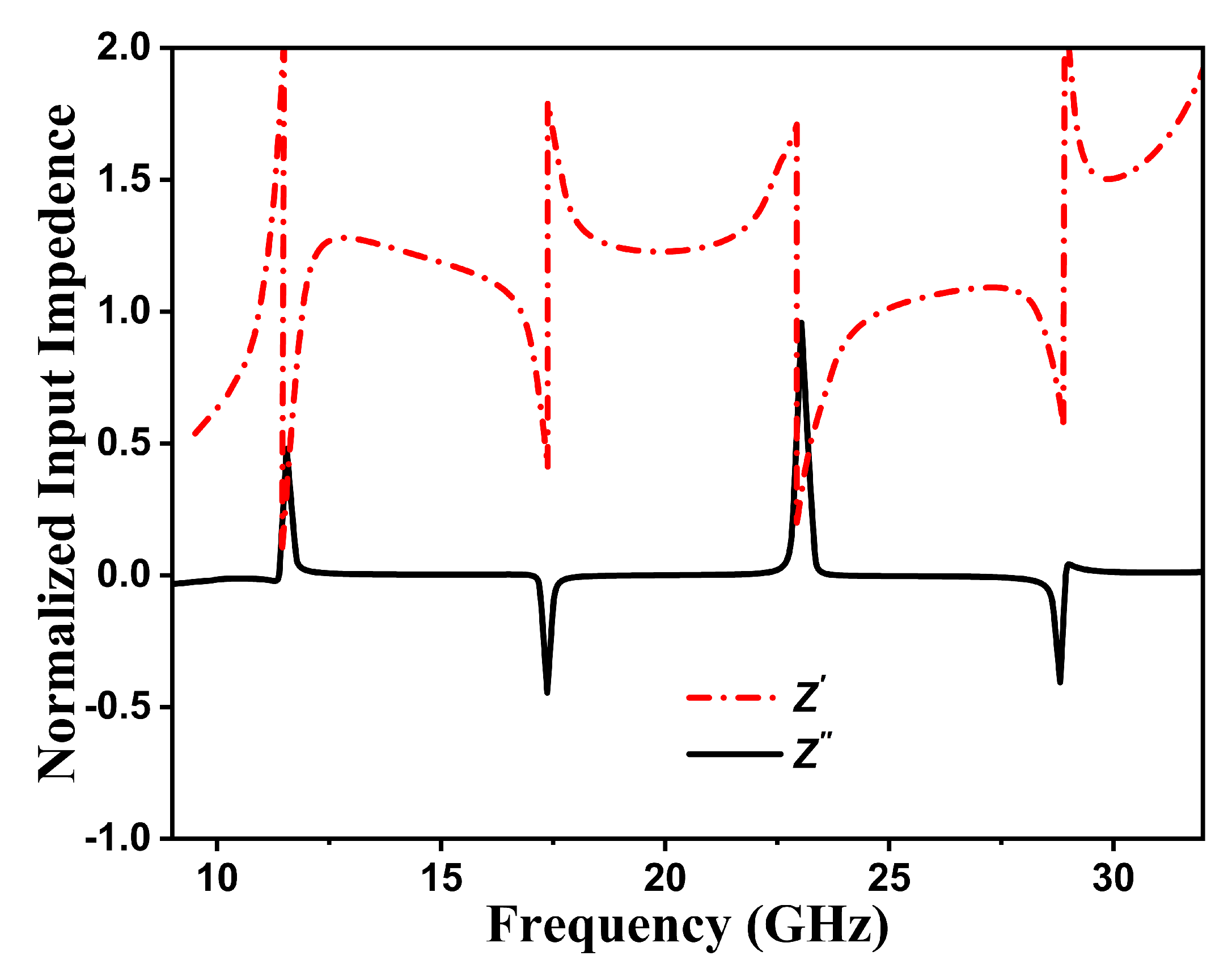
2.2. Absorption Mechanism and Impedence Matching

Because metasurfaces are made up of sub-wavelength periodic structures, their absorption characteristics can be studied using the effective medium theory [39]. The absorption A ( ω ) can be calculated using the following Equation [40].
A ( ω ) = 1 R ( ω ) T ( ω )
In Equation (1), ω denotes angular frequency, while R ( ω ) and T ( ω ) denote reflectivity and transmittivity, respectively. Because of the bottom metallic backplate, T ( ω ) is nearly zero, then the absorption would become
A ( ω ) = 1 R ( ω )
where
R ( ω ) = | r x x | 2 + | r x y | 2 or R ( ω ) = | r y y | 2 + | r y x | 2
where r x x , r y y , r x y , and r y x represent co- and cross-polarization components for an x- and y-polarized wave, respectively. When calculating absorption, the co-polarization component of the reflection coefficient cannot be neglected. Figure 3 illustrates the absorption curve of the proposed meta-atom. It can be seen that co-polarization is below −10 dB in the wide frequency range of 11 to 30.5 GHz. There are multiple resonance peaks at 11.84, 17.03, 23.90, and 28.75 GHz with 100% absorption, and the band with the maximum absorption values above 0.9 ranges from 11 to 30.5 GHz, which has an absorption rate greater than 90%.
Furthermore, impedance matching is used to provide deeper insight into the absorption mechanism of the proposed structure. According to Equation (4), optimal impedance matching can be achieved when the normalized impedance of a structure becomes nearly equal to the free space impedance (377 + j0) Ω . For better impedance matching, the real part (Z ) of an input impedance must be nearly equal to unity, whereas the imaginary part (Z ) close to zero. Figure 4 depicts the normalized input impedance of a proposed structure. In the UWB range, the Z close to 1 and the Z curve close to zero suggest that the proposed structure has a good match with free space, which generates wideband absorption as a result.
Z = 1 + S 11 1 S 11

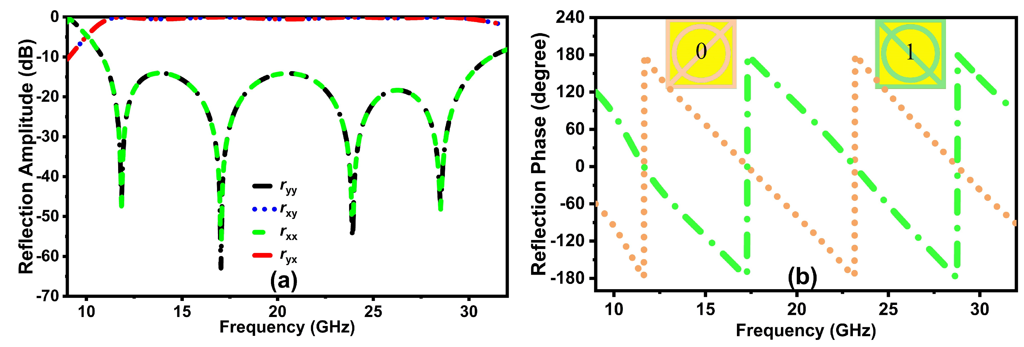
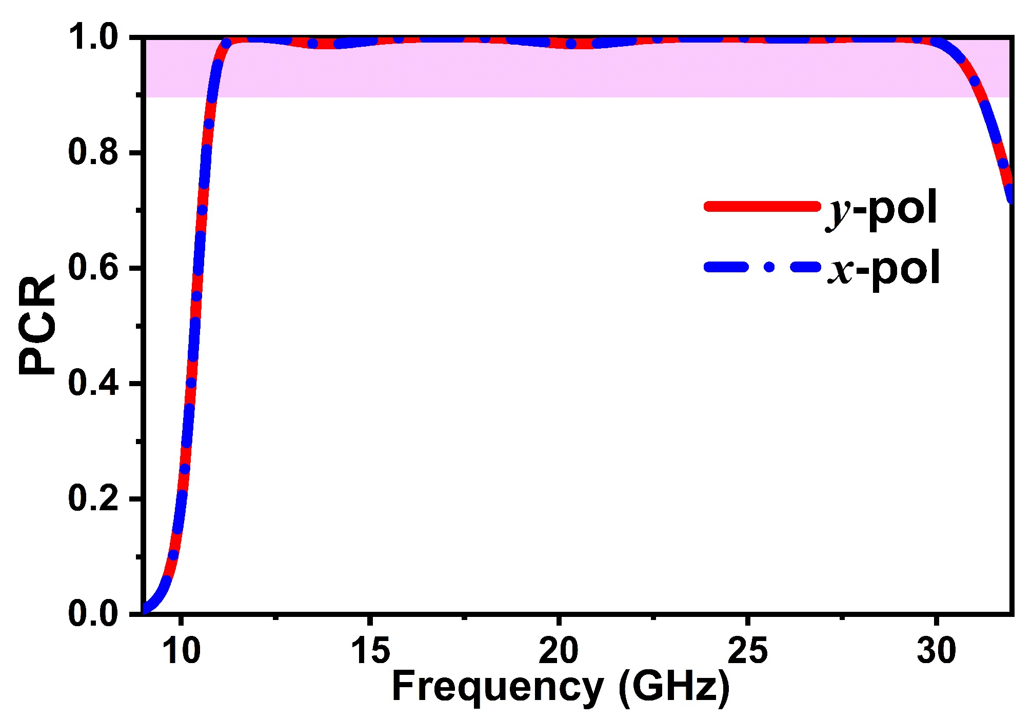
2.3. Polarization Conversion Mechanism

Moreover, the proposed meta-atom is also capable of ultra broadband polarization conversion. The polarization conversion performance is described by the polarization conversion ratio (PCR). For a linearly polarized incident wave, PCR can be calculated as follows:
PCR x = | r y x | 2 | r y x | 2 + | r x x | 2 and PCR y = | r x y | 2 | r x y | 2 + | r y y | 2
where PCR x and PCR y represent the polarization conversion efficiency in the presence of linearly polarized x- and y-incidence waves, respectively. The polarization conversion performance of a meta-atom is shown in Figure 5. As depicted, a wide frequency band ranging from 10.8 to 31.3 GHz possesses a polarization conversion value higher than 0.9 dB with four resonance peaks at 11.84, 17.03, 23.90, and 28.75 GHz that reach unity. It indicates that the proposed meta-atom has a high polarization conversion efficiency and is capable of performing polarization conversion.
To better understand the working principle of the proposed structure, we presented the u- and v-axes, which are obtained by rotating the x- and y-axes by 45 anticlockwise, as presented in Figure 6a. The equations for the incident and reflected waves are as follows:
E i = y ^ E i = u ^ E i u + v ^ E i v
E r = u ^ E r u + v ^ E r v = u ^ r u E i u + v ^ r v E i v
The unit vectors are represented by u ^ and v ^ , whereas the reflection coefficients in the u and v-axes are denoted by r u and r v , respectively. Equation (7) is further simplified as [41]:
E r = u ^ r u u E i u e i ϕ u u + r u v E i v e i ϕ u v + v ^ r v v E i v e i ϕ v v + r v u E i u e i ϕ v u
In Equation (8), r u u , r v v , r u v , and r v u are the co- and cross-reflection coefficients’ magnitudes, and their phases are given as ϕ u u , ϕ v v , ϕ u v and ϕ v u in u- and v-axes, respectively.
To evaluate the properties of the proposed meta-atom, Figure 6b,c depict the magnitude and phase response of the reflection coefficients of u- and v-waves as a function of frequency. The amplitudes of the co- (| R u u |, | R v v |) and cross-polarized (| R u v |, | R v u |) reflection coefficients are shown in Figure 6b. It is observed that | R u u | and | R v v | are greater than 0.9 in the desired frequency range, whereas | R u v | and | R v u | are nearly zero. Furthermore, as illustrated in Figure 6c, the phase difference between the reflected u- and v-polarized waves in the entire frequency range is approximately ±180 , indicating that the designed converter can perform linear cross-polarization conversion over a wide frequency range [42].
Furthermore, the polarization conversion phenomenon is illustrated through surface current distribution. The surface current distribution on top and bottom layers at multiple resonance frequencies (11.84, 17.03, 23.90, and 28.75 GHz) is shown in Figure 7a–h, which is either generated by electric or magnetic resonance of a proposed converter. Specifically, electric resonance will be generated if the surface current distribution on the top metallic pattern and bottom ground plane are parallel, whereas magnetic resonance will occur if current is induced on the top and bottom metallic plates in the opposite direction. At 11.84 and 17.03, the surface currents at the top layer are opposite those on the ground plate, which results in magnetic resonance. However, unlike 11.84 and 17.03, the current distribution at the top and bottom layers is in a similar direction at 23.90 and 28.75 GHz, which will cause an electric resonance. As reported in [43], the strong electromagnetic resonance can be attributed to the effective polarization conversion of the metasurface in the conversion band. According to the literature, the combination of PCRs’ near resonance frequencies is the primary cause of the high efficiency and broad bandwidth of polarization converters [42].
The PCR is further analyzed to realize the effect of geometric parameters on its performance using a parametric analysis. On the basis of this analysis, we can obtain the optimized structure depicted in Figure 1. These parameters include the air gap, substrate height, inner ring, and diagonal strip. In Figure 8a, the effect of the air gap on PCR is shown by changing its size from its optimal value, i.e., 1.6 mm. It has been observed that the PCR bandwidth increases in proportion to the increase in the width of the air gap. However, a further increase in width (from 1.6 to 1.8 mm) will affect the efficiency and bandwidth of a meta-atom, so 1.6 mm is chosen as the optimal size to achieve high polarization conversion efficiency in a wide frequency band. Another critical parameter of the proposed meta-atom is the substrate thickness. The substrate thickness and resonant frequency have an inverse relationship, according to Maxwell’s principle of scale invariance. As shown in Figure 8b, when the thickness of a substrate is changed from 0.2 to 0.3 mm, a negligible change is observed in the results. Moreover, the truncated ring structure and diagonal strip also play an important role. In Figure 8c, the variation of polarization conversion is shown by changing the outer radius r of a truncated ring structure. As it can be seen, through proper optimization, we can achieve a highly efficient response from a meta-atom converter along with a UWB response. Similarly, Figure 8d depicts the optimization results of PCR by varying the thickness of the diagonal strip. Because 0.3 mm achieves high efficiency and a wide frequency band, it is chosen as the optimize parameter.

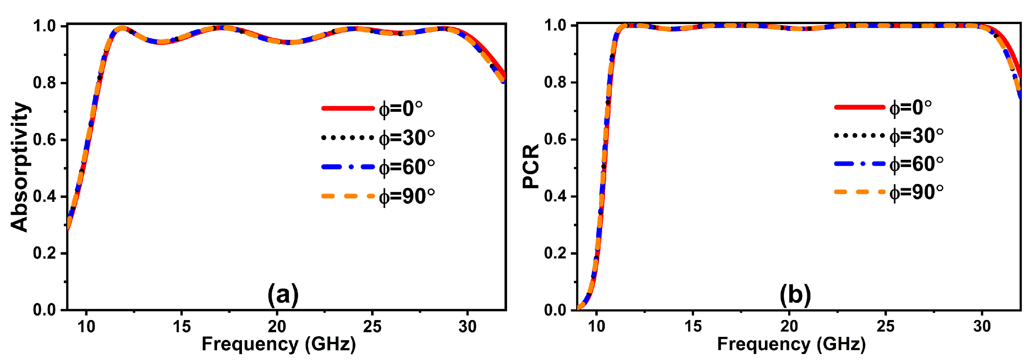
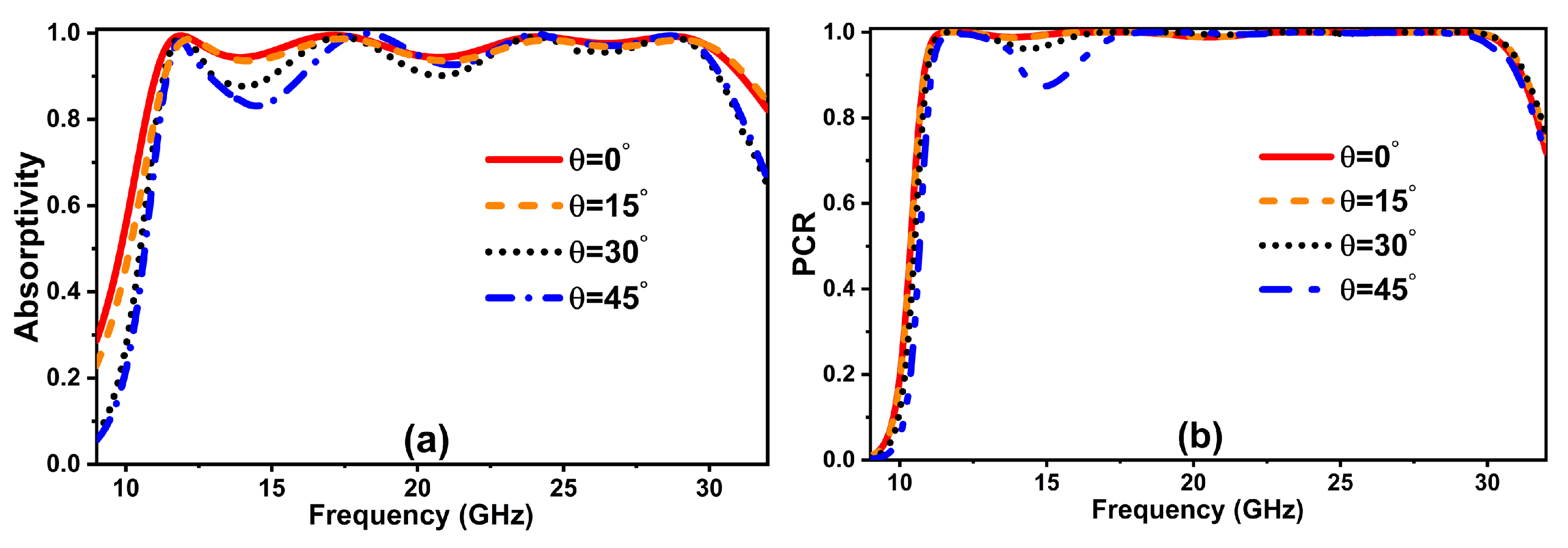
2.4. Polarization and Incidence Angle Variations

In Figure 9, the proposed meta-atom response is analyzed under different polarization angles ( ϕ ) to gain a better understanding of the polarization-independent behavior of a structure. The incident wave direction remains constant, whereas the electric (E-) and magnetic (H-) field directions rotate by an angle of ϕ . Figure 9a,b depict the results for absorption and PCR, respectively. As can be seen, regardless of angle variation from 0 to 90 , a similar response for absorption and PCR is obtained. As a result, the proposed structure is referred to as being polarization independent.
Next, absorption and PCR are investigated under oblique incidence. In this case, the E-field remains unchanged while the incident propagation direction and H-field rotate with a different incident angle ( θ ). Figure 10a shows the absorption performance of a meta-atom under an oblique incident EM wave. According to the results, more than 0.8 dB of absorption is realized up to a 45 incident angle. However, it is observed that absorption efficiency drops slightly with an increase in angle. It is because when EM waves strike a surface at an angle, they cause an increase in reflection, which reduces absorption. Similarly, the oblique performance of a designed meta-atom is examined for polarization conversion. As depicted in Figure 10b, a stable response is achieved up to a 45 incident angle. Considering these attributes, the proposed structure is a good contender for a conformal metasurface.

3. Configuration and Analysis of a Coding Metasurface for RCS Reduction

3.1. Planar Metasurface

To evaluate the RCS performance, polarization conversion absorbing meta-atoms are used to construct a 1-bit coding metasurface with lattices, where each lattice is a subarray of “0” and “1” meta-atoms. Each lattice is assigned a scattering phase of 0 or π . According to [44], “001001110101” is the optimized sequence of the lattices “0” and “1” that can achieve more than 10 dB RCS reduction whenever the phase difference between them lies in the vicinity of π . Figure 11a depicts the overall layout of the optimized coding metasurface (MS1), with the red pattern representing lattice “0” and the yellow pattern representing lattice “1”. Adding to that, the metasurface with chessboard coding sequences (MS2) is also analyzed to verify the universal applicability of the design scheme, as shown in Figure 11b.
The CST Time Domain Solver is used with open add-space boundary conditions in all directions to examine the RCS reduction characteristics of proposed metasurfaces. The linearly polarized plane waves are impinged in the negative z-direction. Moreover, λ /4 is the distance between the metasurface and the plane wave. The RCS reduction performance of a metasurface is provided by normalizing the backscattered results of a metasurface with a metallic slab of the same size. Figure 12a shows the monostatic RCS reduction for MS1 and MS2 under normal x- and y-polarized incidence waves. As depicted in the figure, a considerable RCS reduction of at least −10 dB can be achieved for both metasurfaces in the operating frequency range (10.8–31.3 GHz). The maximum reduction in RCS can be observed at the four resonance frequencies where the PCR and absorption values are 100%. Moreover, it is observed that MS1 has a slightly better effect on the RCS reduction performance compared to MS2. This is due to the fact that the arrangement sequence of meta-atoms was optimized in MS1. Figure 12b depicts normalized monostatic RCS reduction results for MS1 for differently polarized states. There is a slight distinction between x- and y-polarized normal incidence; however, the trend is fundamentally the same for all the polarization states. These findings also suggest that the proposed checkerboard metasurface possesses polarization-insensitive characteristics, which are vitally important for real-world applications.
To further illustrate the working principle of MS1, Figure 13a–d depict the three-dimensional (3-D) far-field scattering patterns under normal incidence waves at 12, 18, 24, and 30 GHz, respectively. It is observed that the incident EM wave is reflected equally in all directions, resulting in a substantial decrease in the backward RCS.

3.2. Parametric Analysis

A parametric study has been performed to investigate how fabrication flaws can influence a metasurface’s efficiency. To determine the effect of the thickness of the dielectric substrate on the response of the metasurface, a sweep was performed under varying thicknesses, ranging from 0.154 to 0.354 mm, while all other parameters remained constant. Figure 14a illustrates the acquired RCS reduction values. By changing the value from its optimal state, distant resonance peaks and frequency band shifts are realized. Similarly, the sweeps for ϵ r and h air have also been performed, as depicted in Figure 14b,c and optimized RCS reduction results have been achieved. However, if the manufacturing process is good and handled with care, these tolerances can be kept to a minimum, and measurement results can be produced that are nearly the same as numerical results.

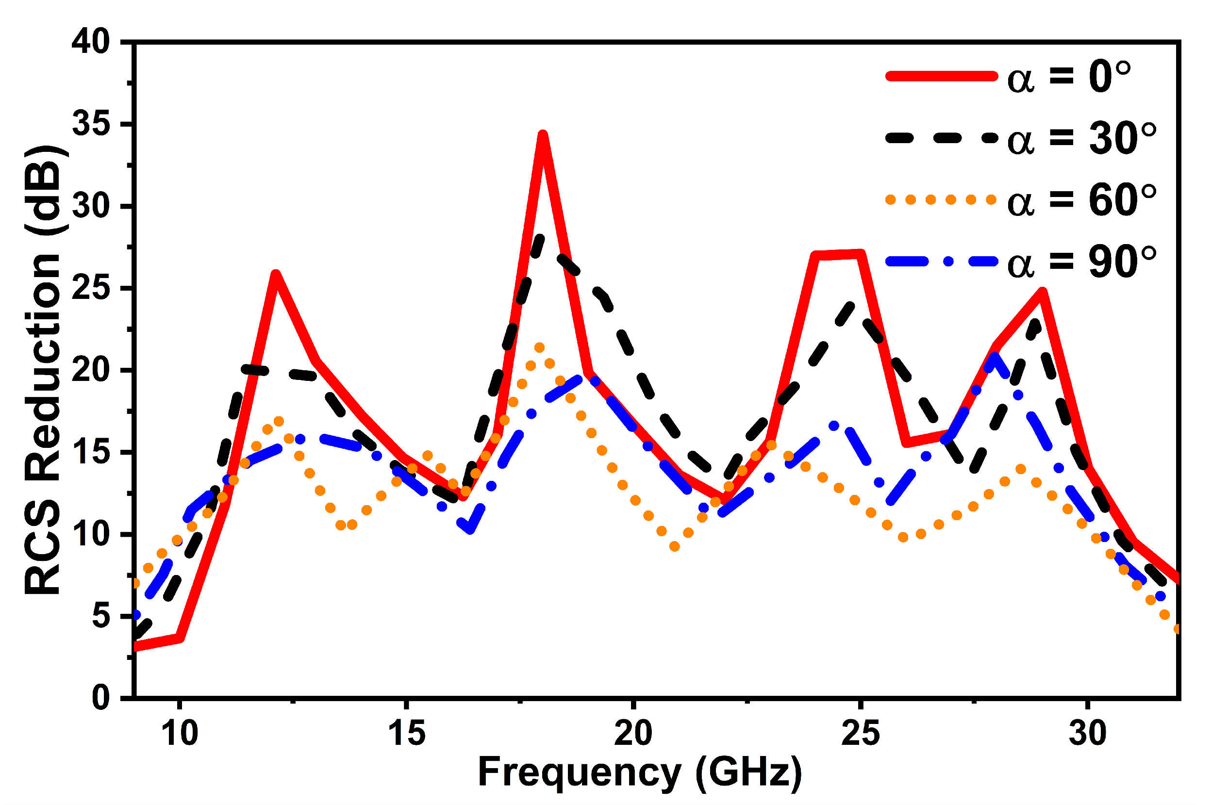
3.3. Conformal Metasurface

Achieving RCS reduction of a conformal metasurface is the current trend for researchers due to the non-planar characteristics of many microwave and wireless communication applications such as combat jets, ships, radomes, and missiles. The scattering response is highly dependent on the surface curvature, as the incidence angle of EM waves varies with surface curvature. As shown in Figure 15, the proposed coding metasurface is conformally bent with a curvature radius of 30 , 60 , and 90 so that the RCS reduction characteristic of a curved surface can be analyzed. A full-wave simulation, such as a planar metasurface simulation, simulates plane waves along the negative z-axis under normal incidence. Numerical simulations are also performed on the equal-size metallic cylinder as a reference. In order to demonstrate how the various curvature radii affect the lowering of the backwards RCS, a simulation of the monostatic RCS was performed with a variety of different curvature radii.
The comparisons of the monostatic RCS reduction between planar and conformal arrays with various curvature radii under a normal plane wave are depicted in Figure 16. It is discovered that for a planar surface ( α = 0), an RCS reduction of more than 10 dB is achieved from 10.8 to 31.3 GHz with a fractional bandwidth of 97%. Moreover, the RCS reduction bandwidth is almost completely sustained up to central angles of 90 degrees for conformal metasurfaces since the performance of the proposed meta-atom is stable up to an incidence angle of 45 . In the case of conformal configuration, the surface is curved so that EM waves are incident obliquely, which will affect the reflection phase characteristics of an incident wave and result in a decrease in RCS reduction performance. In short, the lower the backward RCS, the greater the structure’s bend.
Table 1 provides a comparison between the study presented and previously published work. Broadband RCS reduction, low profile, simplicity, flexibility, and wide-angle stability are some of the benefits of the suggested concept compared to previously reported designs.

4. Conclusions

In this work, a polarization-independent coding metasurface is proposed with broadband RCS reduction for planar as well as conformal surfaces based on polarization conversion, diffusion, and absorption (PCDA) mechanisms. Meta-atom "0" consists of a slotted ring structure with a diagonal strip. Taking advantage of the PB phase, meta-atom "1" is achieved to construct a 1-bit coding metasurface. The optimized arrangement of meta-atoms in a coding metasurface will cause low backward scattering over a wide frequency range by utilizing diffusion and absorption simultaneously. The metasurface can reduce reflection by more than 10 dB for all azimuth angles from 10.8 to 31.3 GHz. In addition to this, the designed metasurface also has the ability to maintain RCS reduction in wideband for curved surfaces. This strategy of combining PCDA mechanisms with excellent angular and polarization stability has great potential for application in stealth EM technologies.

Author Contributions

Conceptualization, H.A.K., U.R., S.M.A. and A.M.; methodology, H.A.K. and S.M.A.; software, H.A.K.; validation, S.M.A., F.A., Y.H., J.A.U. and A.M.; formal analysis, H.A.K., U.R., S.M.A., J.A.U.; investigation, H.A.K., F.A. and Y.H.; resources, S.M.A. and F.A.; writing---original draft preparation, H.A.K.; writing---review and editing, U.R., S.M.A., F.A. and A.M.; visualization, H.A.K. and U.R.; supervision, U.R., S.M.A., Y.H., J.A.U. and A.M.; funding acquisition, S.M.A. All authors have read and agreed to the published version of the manuscript.

Funding

This research received no external funding.

Institutional Review Board Statement

Not applicable.

Informed Consent Statement

Not applicable.

Conflicts of Interest

The authors declare no conflict of interest.

References

  1. Jayalakshmi, C.; Inamdar, A.; Anand, A.; Kandasubramanian, B. Polymer matrix composites as broadband radar absorbing structures for stealth aircrafts. J. Appl. Polym. Sci. 2019, 136, 47241. [Google Scholar] [CrossRef] [Green Version]
  2. Banga, N. Research Article Research on Stealth Aircraft and Its Effect on Radar System in Modern Warfare. Int. J. Curr. Res. 2017, 9, 55654–55658. [Google Scholar]
  3. Sang, D.; Chen, Q.; Ding, L.; Guo, M.; Fu, Y. Design of checkerboard AMC structure for wideband RCS reduction. IEEE Trans. Antennas Propag. 2019, 67, 2604–2612. [Google Scholar] [CrossRef]
  4. Joy, V.; Dileep, A.; Abhilash, P.; Nair, R.U.; Singh, H. Metasurfaces for stealth applications: A comprehensive review. J. Electron. Mater. 2021, 50, 3129–3148. [Google Scholar] [CrossRef]
  5. Lu, C.; Mei, Z.L.; Tang, W.X.; Cui, T.J. Manipulating scattering features by metamaterials. EPJ Appl. Metamater. 2016, 3, 3. [Google Scholar] [CrossRef] [Green Version]
  6. Xu, H.X.; Ma, S.; Ling, X.; Zhang, X.K.; Tang, S.; Cai, T.; Sun, S.; He, Q.; Zhou, L. Deterministic approach to achieve broadband polarization-independent diffusive scatterings based on metasurfaces. ACS Photonics 2017, 5, 1691–1702. [Google Scholar] [CrossRef]
  7. Zhu, H.; Li, Q.; Tao, C.; Hong, Y.; Xu, Z.; Shen, W.; Kaur, S.; Ghosh, P.; Qiu, M. Multispectral camouflage for infrared, visible, lasers and microwave with radiative cooling. Nat. Commun. 2021, 12, 1805. [Google Scholar] [CrossRef]
  8. Chen, Z.; Segev, M. Highlighting photonics: Looking into the next decade. ELight 2021, 1, 2. [Google Scholar] [CrossRef]
  9. Song, S.; Ma, X.; Pu, M.; Li, X.; Guo, Y.; Gao, P.; Luo, X. Tailoring active color rendering and multiband photodetection in a vanadium-dioxide-based metamaterial absorber. Photonics Res. 2018, 6, 492–497. [Google Scholar] [CrossRef] [Green Version]
  10. Fu, C.; Sun, Z.; Han, L.; Liu, C. Dual-bandwidth linear polarization converter based on anisotropic metasurface. IEEE Photonics J. 2020, 12, 1–11. [Google Scholar] [CrossRef]
  11. Jia, M.; Wang, Z.; Li, H.; Wang, X.; Luo, W.; Sun, S.; Zhang, Y.; He, Q.; Zhou, L. Efficient manipulations of circularly polarized terahertz waves with transmissive metasurfaces. Light Sci. Appl. 2019, 8, 16. [Google Scholar] [CrossRef] [PubMed] [Green Version]
  12. Kowerdziej, R.; Jaroszewicz, L.; Olifierczuk, M.; Parka, J. Experimental study on terahertz metamaterial embedded in nematic liquid crystal. Appl. Phys. Lett. 2015, 106, 092905. [Google Scholar] [CrossRef]
  13. Yatooshi, T.; Ishikawa, A.; Tsuruta, K. Terahertz wavefront control by tunable metasurface made of graphene ribbons. Appl. Phys. Lett. 2015, 107, 053105. [Google Scholar] [CrossRef]
  14. Nouman, M.T.; Hwang, J.H.; Faiyaz, M.; Lee, K.J.; Noh, D.Y.; Jang, J.H. Vanadium dioxide based frequency tunable metasurface filters for realizing reconfigurable terahertz optical phase and polarization control. Opt. Express 2018, 26, 12922–12929. [Google Scholar] [CrossRef]
  15. Li, J.S.; Zhou, C. Transmission-type terahertz beam splitter through all-dielectric metasurface. J. Phys. D Appl. Phys. 2020, 54, 085105. [Google Scholar] [CrossRef]
  16. Huang, S.; Fan, Q.; Xu, C.; Wang, B.; Wang, J.; Yang, B.; Tian, C.; Meng, Z. A visible-light-transparent camouflage-compatible flexible metasurface for infrared–radar stealth applications. J. Phys. D Appl. Phys. 2020, 54, 015001. [Google Scholar] [CrossRef]
  17. Chen, W.; Balanis, C.A.; Birtcher, C.R. Checkerboard EBG surfaces for wideband radar cross section reduction. IEEE Trans. Antennas Propag. 2015, 63, 2636–2645. [Google Scholar] [CrossRef]
  18. Munk, B.A.; Munk, P.; Pryor, J. On designing Jaumann and circuit analog absorbers (CA absorbers) for oblique angle of incidence. IEEE Trans. Antennas Propag. 2007, 55, 186–193. [Google Scholar] [CrossRef]
  19. Song, J.; Wu, X.; Huang, C.; Yang, J.; Ji, C.; Zhang, C.; Luo, X. Broadband and tunable RCS reduction using high-order reflections and salisbury-type absorption mechanisms. Sci. Rep. 2019, 9, 9036. [Google Scholar] [CrossRef] [Green Version]
  20. Wang, X.; Du, Z.; Hou, M.; Ding, Z.; Jiang, C.; Huang, X.; Yue, J. Design method of structural microwave absorber by frequency characteristic analysis of reflectivity function. Opt. Commun. 2022, 510, 127885. [Google Scholar] [CrossRef]
  21. Rafique, U.; Kiani, G.I.; Ahmed, M.; Habib, S. Frequency selective surface absorber for WLAN security. In Proceedings of the Proceedings of the 5th European Conference on Antennas and Propagation (EUCAP), Rome, Italy, 11–15 April 2011; pp. 872–875. [Google Scholar]
  22. Zhang, Y.; Miao, L.; Guo, S.; Huang, Z.; Cao, Z.; He, Y.; Wei, J.; Li, C.; Jiang, J. A broadband tunable frequency selective surface absorber for oblique incidence applications. J. Phys. D Appl. Phys. 2019, 53, 055105. [Google Scholar] [CrossRef]
  23. Li, W.; Zhang, Y.; Wu, T.; Cao, J.; Chen, Z.; Guan, J. Broadband radar cross section reduction by in-plane integration of scattering metasurfaces and magnetic absorbing materials. Results Phys. 2019, 12, 1964–1970. [Google Scholar] [CrossRef]
  24. Zhang, C.; Yin, S.; Long, C.; Dong, B.W.; He, D.; Cheng, Q. Hybrid metamaterial absorber for ultra-low and dual-broadband absorption. Opt. Express 2021, 29, 14078–14086. [Google Scholar] [CrossRef] [PubMed]
  25. Min, P.; Song, Z.; Yang, L.; Dai, B.; Zhu, J. Transparent ultrawideband absorber based on simple patterned resistive metasurface with three resonant modes. Opt. Express 2020, 28, 19518–19530. [Google Scholar] [CrossRef] [PubMed]
  26. Liu, P.; Li, W.; Chen, N.; Ma, C.; Li, X.; Yan, D. Enhancing the Terahertz Absorption Spectrum Based on the Low Refractive Index All-Dielectric Metasurface. Photonics 2022, 9, 848. [Google Scholar] [CrossRef]
  27. Khan, H.A.; Huang, C.; Xiao, Q.; Abbas, S.M. Polarization-Dependent Coding Metasurface with Switchable Transmission and RCS Reduction Bands. Micromachines 2023, 14, 78. [Google Scholar] [CrossRef] [PubMed]
  28. Li, S.; Li, J. Manipulating terahertz wave and reducing radar cross section (RCS) by combining a Pancharatnam–Berry phase with a coding metasurface. Laser Phys. 2019, 29, 075403. [Google Scholar] [CrossRef]
  29. Yuan, F.; Chen, Q.; Zheng, Y.; Fu, Y. Dual-Mechanism Absorptive Metasurface with Wideband 20 dB RCS Reduction. Crystals 2022, 12, 493. [Google Scholar] [CrossRef]
  30. Zhu, Z.; Li, Y.; Jing, Y.; Wang, J.; Zhang, J.; Qu, S. Ultra-wideband RCS reduction based on coupling effects between beam diffuse and absorptive structures. Opt. Express 2022, 30, 3820–3834. [Google Scholar] [CrossRef]
  31. Ran, Y.; Shi, L.; Wu, S.; Fan, B.; Jin, X.; Ji, D.; Ma, Y.; Li, J.; Liu, Y.; Wang, J. Optically Transparent Low Scattering Metasurface Based on Polarization Conversion-Diffusion-Absorption Integration Mechanism. Adv. Theory Simul. 2022, 5, 2100531. [Google Scholar] [CrossRef]
  32. Hu, S.; Du, W.; Zhang, D.; Xu, W.; Chen, X.; Zhang, X. Multi-Channel Polarization Manipulation Based on All-Dielectric Metasurface. Photonics 2022, 9, 847. [Google Scholar] [CrossRef]
  33. Ruffato, G.; Capaldo, P.; Massari, M.; Mezzadrelli, A.; Romanato, F. Pancharatnam–Berry optical elements for spin and orbital angular momentum division demultiplexing. Photonics 2018, 5, 46. [Google Scholar] [CrossRef] [Green Version]
  34. Kalraiya, S.; Ameen, M.; Chaudhary, R.K.; Gangwar, R.K. Compact ultrathin conformal metamaterial dual-band absorber for curved surfaces. Int. J. RF Microwave Comput.-Aided Eng. 2019, 29, e21929. [Google Scholar] [CrossRef]
  35. Chen, H.; Ma, H.; Wang, J.; Qu, S.; Pang, Y.; Yan, M.; Li, Y. Ultra-wideband transparent 90 polarization conversion metasurfaces. Appl. Phys. A 2016, 122, 1–5. [Google Scholar] [CrossRef]
  36. Chen, H.Y.; Wang, J.F.; Ma, H.; Qu, S.B.; Zhang, J.Q.; Xu, Z.; Zhang, A.X. Broadband perfect polarization conversion metasurfaces. Chin. Phys. B 2015, 24, 014201. [Google Scholar] [CrossRef]
  37. Khan, M.I.; Fraz, Q.; Tahir, F.A. Ultra-wideband cross polarization conversion metasurface insensitive to incidence angle. J. Appl. Phys. 2017, 121, 045103. [Google Scholar] [CrossRef]
  38. Liang, Y.; Lin, H.; Lin, S.; Wu, J.; Li, W.; Meng, F.; Yang, Y.; Huang, X.; Jia, B.; Kivshar, Y. Hybrid anisotropic plasmonic metasurfaces with multiple resonances of focused light beams. Nano Lett. 2021, 21, 8917–8923. [Google Scholar] [CrossRef]
  39. Smith, D.R. Analytic expressions for the constitutive parameters of magnetoelectric metamaterials. Phys. Rev. E 2010, 81, 036605. [Google Scholar] [CrossRef] [Green Version]
  40. Rahman, S.U.; Yi, W.; Cao, Q. Comments on “An Ultrathin and Ultrawideband Metamaterial Absorber and an Equivalent-Circuit Parameter Retrieval Method”. IEEE Trans. Antennas Propag. 2020, 68, 8272–8273. [Google Scholar] [CrossRef]
  41. Nguyen, T.K.T.; Nguyen, T.M.; Nguyen, H.Q.; Cao, T.N.; Le, D.T.; Bui, X.K.; Bui, S.T.; Truong, C.L.; Vu, D.L.; Nguyen, T.Q.H. Simple design of efficient broadband multifunctional polarization converter for X-band applications. Sci. Rep. 2021, 11, 2032. [Google Scholar] [CrossRef]
  42. Xu, J.; Li, R.; Wang, S.; Han, T. Ultra-broadband linear polarization converter based on anisotropic metasurface. Opt. Express 2018, 26, 26235–26241. [Google Scholar] [CrossRef] [PubMed]
  43. Fang, S.; Deng, L.; Zhang, P.; Qiu, L.; Xie, H.; Huang, S.; Du, J.; Wang, Z. Dual-function flexible metasurface for absorption and polarization conversion and its application for radar cross section reduction. J. Appl. Phys. 2022, 131, 135106. [Google Scholar] [CrossRef]
  44. Cui, T.J.; Qi, M.Q.; Wan, X.; Zhao, J.; Cheng, Q. Coding metamaterials, digital metamaterials and programmable metamaterials. Light Sci. Appl. 2014, 3, e218. [Google Scholar] [CrossRef] [Green Version]
  45. Murugesan, A.; Natarajan, D.; Selvan, K.T. Low-cost, wideband checkerboard metasurfaces for monostatic RCS reduction. IEEE Antennas Wirel. Propag. Lett. 2021, 20, 493–497. [Google Scholar] [CrossRef]
  46. Feng, M.; Chen, X.; Li, Y.; Zheng, Q.; Han, Y.; Zhang, J.; Wang, J.; Hou, Y.; Liu, Z.; Li, X.; et al. Circularly Polarized Spin-Selectivity Absorbing Coding Phase Gradient Metasurface for RCS Reduction. Adv. Theory Simul. 2020, 3, 1900217. [Google Scholar] [CrossRef]
  47. Chatterjee, J.; Mohan, A.; Dixit, V. Ultrawideband RCS Reduction of Planar and Conformal Surfaces Using Ultrathin Polarization Conversion Metasurface. IEEE Access 2022, 10, 36563–36575. [Google Scholar] [CrossRef]
  48. Yuan, F.; Xu, H.X.; Jia, X.Q.; Wang, G.M.; Fu, Y.Q. RCS reduction based on concave/convex-chessboard random parabolic-phased metasurface. IEEE Trans. Antennas Propag. 2019, 68, 2463–2468. [Google Scholar] [CrossRef]
  49. Qi, Y.; Zhang, B.; Liu, C.; Deng, X. Ultra-broadband polarization conversion meta-surface and its application in polarization converter and RCS reduction. IEEE Access 2020, 8, 116675–116684. [Google Scholar] [CrossRef]
  50. Zhao, Y.T.; Chen, J.; Wei, Y.; Zhang, C.; Li, L.; Wu, B.; Su, T. Single-layer absorption-diffusion-integrated metasurface for high-performance radar cross section reduction using hybrid copper–graphene structure. J. Appl. Phys. 2022, 131, 165108. [Google Scholar] [CrossRef]
Figure 1. (a) Top and (b) side view of a meta-atom. P = 6 mm, l = 4.8 mm, r = 2.4 mm, s = 0.3 mm, w = 0.5 mm, h = 0.254 mm, and h a i r = 1.6 mm. (c) Three-dimensional view of simulation setup.
Photonics 10 00281 g001
Figure 2. (a) Reflection amplitudes of meta-atom “0” under linear polarizations. (b) Cross-polarization reflection phases of meta-atom “0” and “1”.
Photonics 10 00281 g002
Figure 3. Reflection coefficient and absorptivity of the proposed structure.
Photonics 10 00281 g003
Figure 4. Normalized input impedance of the proposed meta-atom.
Photonics 10 00281 g004
Figure 5. Polarization conversion ratio under normal x- and y-polarized waves.
Photonics 10 00281 g005
Figure 6. (a) Schematic diagram of the proposed meta-atom with u v -coordinates (b) magnitude and (c) phase of the reflection coefficients of v- and u-waves.
Photonics 10 00281 g006
Figure 7. Surface current distribution on the (ad) top and (eh) bottom layer at 11.84, 17.03, 23.90, and 28.75 GHz, respectively.
Photonics 10 00281 g007
Figure 8. Variations in PCR by changing (a) air gap (b) substrate height (c) r and (d) s.
Photonics 10 00281 g008
Figure 9. (a) Absorptivity and (b) PCR responses at different polarization angles.
Photonics 10 00281 g009
Figure 10. (a) Absorptivity and (b) PCR responses at different oblique incidences.
Photonics 10 00281 g010
Figure 11. Schematic diagram of (a) coding metasurface and (b) chessboard metasurface.
Photonics 10 00281 g011
Figure 12. (a) Monostatic RCS reduction of MS1 and MS2. (b) RCS reduction of MS1 for linear and circular polarizations.
Photonics 10 00281 g012
Figure 13. Normalized 3D far-field scattering pattern of a MS1 at (a) 12, (b) 18, (c) 24, and (d) 30 GHz.
Photonics 10 00281 g013
Figure 14. RCS reduction for different (a) h (b) ϵ r and (c) h air under normal x-polarization.
Photonics 10 00281 g014
Figure 15. Illustration of incident EM wave on cylindrical surfaces with different radii.
Photonics 10 00281 g015
Figure 16. Monostatic RCS reductions results of a coding metasurface for various central angles ( α ).
Photonics 10 00281 g016
Table 1. Comparison with state-of-the-art reported work.
Ref.Unit CellFrequency RangeFractionalMechanismTypeRCS Reduction
Size ( λ 3 )(GHz)Bandwidth (%) for α
[25]0.65 × 0.65 × 0.234.3–18.7125AbsorptionFlexible
[29]0.41 × 0.41 × 0.1311.5–1632Absorption+DiffusionNon-flexible
[45]0.39 × 0.39 × 0.194.2–11.693DiffusionNon-flexible
[46]0.35 × 0.35 × 0.1313.02–28.574DiffusionNon-flexible
[47]0.3 × 0.3 × 0.176.3–20.5105DiffusionFlexibleUp to 70
[48]0.46 × 0.46 × 0.157.8–23.299DiffusionNon-flexible
[49]0.45 × 0.45 × 0.132040–533089DiffusionFlexible
[50]0.42 × 0.42 × 0.216.2–19.2102Absorption + DiffusionNon-flexible
This Work0.4 × 0.4 × 0.1110.8–31.397Absorption + DiffusionFlexibleUp to 90
Disclaimer/Publisher’s Note: The statements, opinions and data contained in all publications are solely those of the individual author(s) and contributor(s) and not of MDPI and/or the editor(s). MDPI and/or the editor(s) disclaim responsibility for any injury to people or property resulting from any ideas, methods, instructions or products referred to in the content.

