Abstract
Parhyale hawaiensis is a marine crustacean which has emerged as a powerful model organism to study molecular and cellular mechanisms linked to embryonic development and regenerative processes. Recently, several fluorescence-based optical microscopy techniques have been employed for the study of Parhyale to obtain anatomical descriptions, analyze gene expression patterns and reconstruct cell lineages. Aiming at the expansion of the imaging repertoire for this emerging model organism, we introduce a low-cost hybrid diagnostic system which integrates confocal fluorescence and frequency domain photoacoustic (FDPA) microscopy modalities, concurrently capturing both the radiative and radiationless relaxations of molecules following their excitation by an intensity-modulated laser source. We initially characterize the hybrid microscope in terms of PA signal generation efficiency and lateral spatial resolution, and subsequently evaluate its capabilities for the in vivo imaging of unlabelled and fluorescently labelled Parhyale embryos found at different stages of development. The recorded hybrid images have revealed a remarkable contrast complementarity between the integrated imaging modes, providing valuable information regarding cells’ structure, nuclei location, cellular membranes and yolk distribution. Our findings may pave the way for the broader adoption of inexpensive hybrid optical and PA microscopy methods in developmental biology, significantly upgrading the capabilities of the currently used technologies.
1. Introduction
Image and sequence acquisition and analysis methods are the powerhouses fueling modern day biomedical research. The general applicability of these methodologies has enabled the expansion of the experimental organisms that have been introduced in biological laboratories beyond a handful of more traditional animal models such as roundworms (Caenorhabditis elegans), flies (Drosophila melanogaster), mice (Mus musculus) and zebrafish (Danio rerio) [1]. Among recently established laboratory animals, the amphipod crustacean Parhyale hawaiensis has emerged as an attractive model for developmental genetic, physiological and ecological studies [2,3]. Over the last two decades, Parhyale research has been motivated by and has contributed towards our understanding of the developmental genetic mechanisms underlying body plan and body part evolution [4], appendage diversification [5], evolution [6,7] and the origin of novel morphologies [8], as well as the molecular and cellular mechanisms controlling diverse developmental [9,10,11,12,13] and regenerative processes [14,15,16,17].
Intimately linked with the establishment and advancement of Parhyale as a model system has been the adoption of older and newer light and electron microscopy techniques. Widefield, confocal and light-sheet fluorescence microscopy, and scanning and transmission electron microscopy have been used on live and fixed specimens for detailed morphological and anatomical descriptions [4,13,17], fate mapping experiments [14,18], analyses of gene expression patterns [6,19,20] and comprehensive reconstructions of cell lineages [12,21]. Recently, we expanded the imaging repertoire of Parhyale embryogenesis through the construction and application of a low-cost frequency domain photoacoustic (FDPA) microscope for the label-free reconstruction of live developing embryos [22]. The prototype integrated a continuous wave (CW) laser source with temporally modulated intensity for the efficient excitation of monochromatic PA waves, which were subsequently found to provide amplitude and phase recordings. The data were processed according to the principles formulated in a previous work [23] to generate artifact-free maximum amplitude projection (MAP) images and surface maps, delineating the structural features of the embryos with high spatial resolution and contrast specificity related to the distribution of the optically absorbing yolk.
The aim of the present work is to evaluate the capabilities of a novel hybrid imaging instrument integrating FDPA and traditional confocal microscopy modalities with regard to the investigation of different developmental stages both in unstained and fluorescently labelled Parhyale embryos in vivo. Despite the fact that several hybrid PA instruments have been demonstrated in the literature, the vast majority of the relevant studies integrated highly expensive Q-switched nanosecond lasers for the excitation of the signals, which also presented a limited wavelength availability [22,23]. To that end, we demonstrate that the combination of two contrast mechanisms arising from the radiationless (FDPA) and radiative (fluorescence) molecular relaxations offers highly complementary diagnostic information at a low cost, which may be valuable for shedding light on various fundamental biological mechanisms during development.
2. Materials and Methods
2.1. Technical Description of the Hybrid Microscope
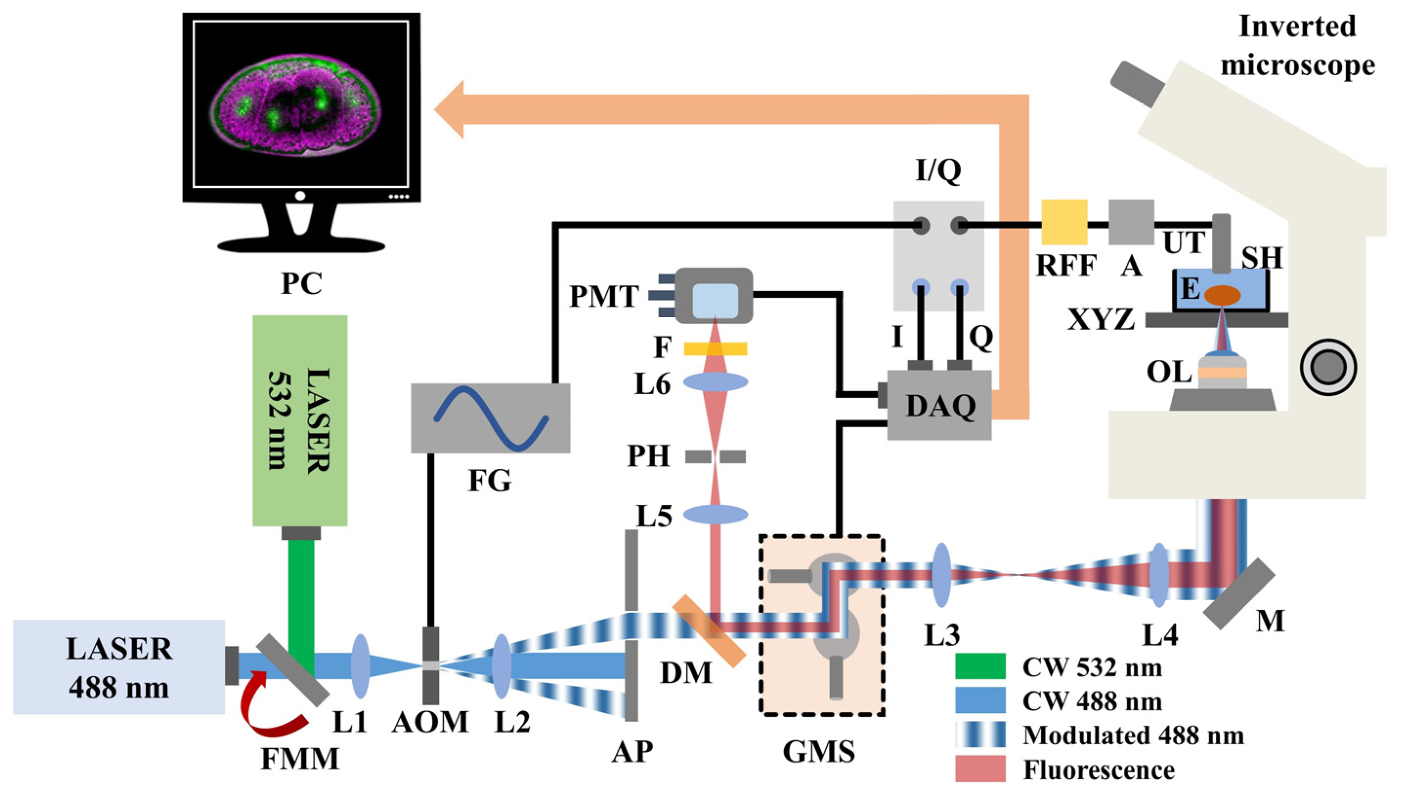
A hybrid fluorescence and FDPA microscope (Figure 1 integrates two continuous wave (CW) laser sources emitting visible radiation at 488 nm (MDL-III-488, CNI, Changchun, China; maximum optical power: 100 mW) and 532 nm (CW532-04-80, Roithner Lasertechnik GmbH, Wien, Austria; maximum optical power: 80 mW), respectively. The desirable excitation wavelength is selected using a flip mount mirror (FMM) which is placed at the intersection point of the two perpendicular laser beam paths. A positive lens (L1) focuses the selected beam on the active aperture of a free-space acousto-optic modulator (AOM; TEM-200-50, Brimrose, Sparks Glencoe, MD, USA), temporally modulating the instantaneous intensity of radiation. For analog modulation, the acousto-optic driver requires the input of a sinusoidal voltage (selected frequency: 9.5 MHz), which is directly provided by an arbitrary function generator (FG; DG5252, Rigol, Beaverton, OR, USA). The outgoing laser light is subsequently collimated using a second positive lens (L2) and filtered through a small aperture (AP) of 5 mm in diameter to isolate the first-order diffraction maximum, corresponding to the useful excitation radiation. The intensity-modulated beam passes through a dichroic mirror (DM; MSR-5051, UQG Optics, Cambridge, UK) and is guided on a galvanometric scanner (GMS; SG2203, Sino-Galvo, Zhenjiang City, China) which is employed to achieve a fast image acquisition. A 4f optical telescope consisting of two positive lenses (L3 and L4) provides sufficient beam expansion (~2.3×) prior to the reflection of radiation by a broadband mirror (M) into a modified inverted optical microscope (Diaphot, Nikon, Tokyo, Japan).
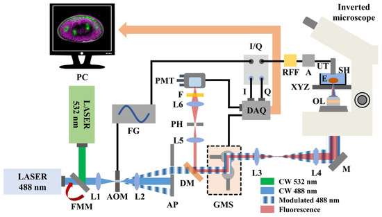
Figure 1.
Schematic illustration of the hybrid microscopy system. Abbreviations: FMM, Flip mount mirror; L(1–6), Lenses; AOM, Acousto-optic modulator; FG, Function generator; AP, Aperture; DM, Dichroic mirror; GMS, Galvanometric mirror scanner; M, Broadband mirror; OL, Objective lens; E, Embryo; XYZ, Microscope’s positioning and focusing system; SH, Sample holder; UT, Ultrasonic transducer; A, RF amplifier; RFF, Bandpass RF filter; I/Q, Demodulator; DAQ, Data acquisition card; PMT, Photomultiplier tube; F, Longpass optical filter; PH, Pinhole; PC, Computer.
An objective lens (OL; Plan Infinity 10X, Cnscope, Beijing, China; numerical aperture: 0.25) focuses the light on the Parhyale hawaiensis embryos (E) which are placed at the bottom of an optically transparent custom-built sample holder (SH) filled with artificial seawater. The sample holder is firmly mounted on the original XY translational stage of the microscope, whereas the focal plane is selected by the focus knob, adjusting the position of the objective lens in the vertical (Z) axis. The generated PA waves are detected by a spherically focused piezoelectric ultrasonic transducer (UT; V312-SU, Olympus, Tokyo, Japan; nominal central frequency: 10 MHz) which is immersed into the sample holder in a slightly out of focus position with respect to the optical focus for field of view extension. The artificial seawater in the sample holder serves additionally as a coupling medium between the signal source and the transducer, ensuring the efficient propagation and detection of the PA waves. The generated signals are initially enhanced by two low-noise amplifiers (A; TB-414-8A+, Mini-Circuits, Camberley, England) connected in series to provide a total gain of 62 dB, and subsequently filtered by a narrow bandpass RF filter (RFF; 10 MHZ BPF, SV1AFN.com, Athens, Greece), efficiently rejecting frequency components which are not present within the 9–11 MHz window. Thereafter, the signals are transmitted in an I/Q demodulator (I/Q; AD8333, Analog Devices, Wilmington, MA, USA) for the assessment of PA amplitude values. The demodulator additionally receives a 4X local oscillator signal at 38 MHz from a second channel of the function generator to provide I and Q values which are digitized by a data acquisition card (DAQ; PCIe-6363, National Instruments, Austin, TX, USA) and recorded by a computer (PC) in synchronization with the galvanometric scanner. The I and Q values are directly used to estimate the amplitude (Amp) of the PA signal through the equation
As has been demonstrated elsewhere [22,23], the PA reconstruction of the embryos results from two distinct imaging sessions which have been performed by providing a phase-shifted voltage by 0° and 90° to the acousto-optic modulator, compared to the local oscillator signal. The final artifact-free PA image C is representative of the embryos’ optical absorption properties and has been calculated by the equation
where A and B are the recorded amplitude images at 0° and 90°, whereas offsetA and offsetB correspond to the respective background amplitude values of the demodulator when no PA signal is received.
With regard to the optical detection path, the backscattered fluorescence radiation is collected by the objective lens of the microscope, transmitted through the 4f beam expansion telescope, de-scanned by the galvanometric mirrors and finally reflected by the dichroic mirror. Using a positive lens (L5), the collimated fluorescence beam is focused through a 50 μm diameter pinhole (PH), to reject the out of focus light, in a typical confocal configuration with the objective lens. The in-focus fluorescence photons are then transmitted through a second positive lens (L6) and filtered by a long-pass optical filter (F; FGL570, Thorlabs, Newton, NJ, USA; cut-off wavelength: 570 nm) to cut-off the reflected portion of the excitation light. The signals are subsequently detected by a low-noise photomultiplier tube (PMT) (H957-15, Hamamatsu, Hamamatsu City, Japan), and finally digitized simultaneously with the acquired I and Q values using a third analog input channel of the DAQ card prior their recording by the computer.
To enhance the signal to noise ratio (SNR) levels, a total number of 200 measurements are averaged for the estimation of the PA amplitude and fluorescence signals per each scanning point. The average power on the sample’s plane has been measured at 20 mW, ensuring that no photodamage effects are observed during the imaging procedure. The resolution of the recorded embryo images is 500 by 500 pixels, corresponding to a pixel size equal to 1.02 μm (field of view: 510 × 510 μm2). The final fluorescence intensity and PA amplitude data have been normalized to their respective maximum values, providing two 8-bit grayscale images. Thus, the ratio of pixel brightness between the two contrast modes is determined by the aforementioned normalization procedures. The recorded images are superimposed with the ImageJ software, using green and magenta color scales for the (auto)fluorescence and PA signal, respectively. Furthermore, the total acquisition time for each imaging session (at 0° and 90°) is approximately equal to 4 min. Control and synchronization of the microscope is performed using custom-developed programs, whereas the recorded data have been processed by means of MATLAB programming environment.
2.2. Preparation of the Parhyale hawaiensis Embryos
Parhyale rearing at 26 °C and embryo collections from anesthetized gravid females were performed using standard procedures, as previously described [24]. Embryos were collected from wild-type laboratory cultures [25], and the PhHS > H2B-mRFPruby transgenic line [14] ubiquitously expressing a heat-inducible, monomeric red fluorescent protein coupled to the Drosophila histone H2B for genetic labeling of all nuclei. Transgenic embryos were heat-shocked for 1 hour (h) at 37 °C to induce the expression of H2B-mRFPruby as previously described [12,24], and were imaged about 24 h later. Chemical labeling of nuclei in early stage wild-type embryos was performed with egg-permeant SYTO® 24 green fluorescent nucleic acid dye (Invitrogen Cat. No. S7559). Wild-type embryos were stained for 1 h in 3 mL filtered artificial seawater (FASW) containing a 1:3000 dilution of SYTO® 24 in a dark environment. They were then washed once with FASW and transferred to a new Petri dish with FASW and kept in the dark until the imaging session.
Unlabelled wild-type embryos, SYTO® 24-stained wild-type embryos and heat-shocked H2B-mRFPruby embryos at the desired embryonic stages (staging according to [25]) were mounted in a drop of 0.7% w/v low melting agarose (SeaPlaque, Lonza, Basel, Switzerland) dissolved in FASW as previously described [22]. Briefly, embryos were mounted on a custom-built sample holder in the appropriate position with fine forceps in the melted agarose. The agarose was left to solidify for 15 min and then covered with FASW for imaging.
3. Results
3.1. Characterization of Intensity Modulation and Spatial Resolution
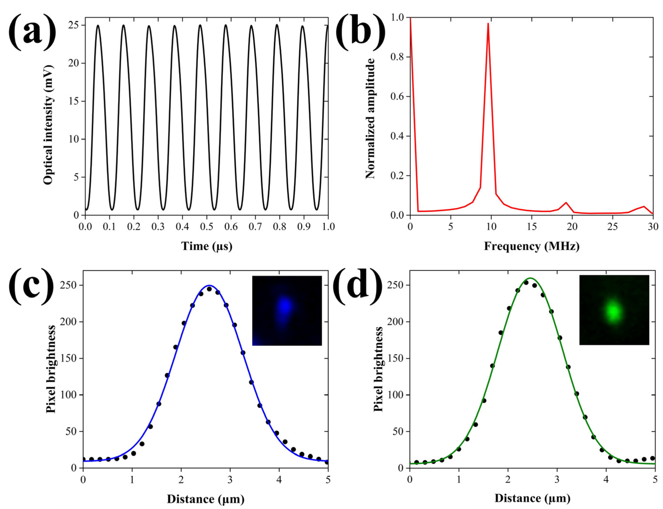
Aiming at the quantitative evaluation of the PA excitation efficiency, we initially recorded the temporal profile of the intensity-modulated laser beam using a fast photodetector module (DET025A, Thorlabs, Newton, NJ, USA; Bandwidth: 2 GHz). Figure 2a depicts the oscillatory behavior of the modulated optical intensity (λ = 488 nm) for a temporal window of 1 μs, following the averaging of 64 waveforms.
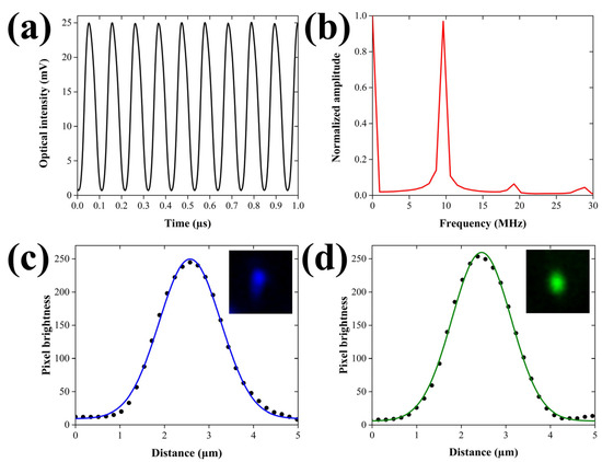
Figure 2.
Temporal and spatial characterization of the excitation beams. (a) Temporal modulation of the excitation laser’s intensity (λ = 488 nm) as measured by a fast photodiode. (b) Normalized amplitude spectrum of the temporal profile shown in (b), demonstrating a predominant peak at 9.5 MHz. (c) Lateral profile of a 520 nm fluorescent microsphere with fitted Gaussian curve, using the 488 nm wavelength. The inset shows the 2D image of the microsphere (field of view: 8.24 × 8.24 μm2). (d) Lateral profile of a 520 nm fluorescent microsphere with fitted Gaussian curve, using the 532 nm wavelength. Similarly, the inset depicts the 2D image of the microsphere for an equal field of view.
The peak-to-peak amplitude of the oscillation has been calculated at 24.3 mV, whereas the respective mean value is estimated at 12.85 mV. The modulation depth, which is defined as one-half of the peak-to-peak changes divided by the mean, is equal to 94.6%, approximating the optimum efficiency for the generation of PA signals. The small deviation from the ideal value of 100% can be attributed to the slightly imperfect response of the acousto-optic modulator at the applied high frequency voltage of 9.5 MHz. It has to be mentioned that the temporal profile of the excitation beam was additionally assessed for the 532 nm wavelength, yielding similar performance indices. Furthermore, a normalized amplitude spectrum was generated by applying a fast Fourier transform (FFT) to the acquired optical waveform, investigating the distribution of energy among the resulting frequency components. The corresponding graph shown in Figure 2b reveals a predominant peak centered at 9.5 MHz, which coincides both with the frequency of the sinusoidal voltage provided by the function generator and the actual central frequency of the ultrasonic transducer as given by the manufacturer. Nevertheless, the spectrum displays two more low-amplitude peaks at 19 and 28.5 MHz, respectively, representing the expected second and third harmonic contributions in the optical modulation. The amplitude ratios between the fundamental frequency and the harmonics have been estimated at 15.16 (second harmonic) and 22.05 (third harmonic), respectively. The aforementioned values are found to be in very good agreement with the specifications of the acousto-optic modulator, verifying the optimum performance of the device. It should be pointed out that the low-magnitude harmonic frequency components are not expected to practically interfere with the detected PA signals due to the use of the narrow bandpass RF filter (9–11 MHz at −3 dB) and the limited bandwidth of the ultrasonic transducer.
A spatial resolution characterization of the hybrid microscope was subsequently realized prior to the investigation of Parhyale hawaiensis embryos, aiming at estimating the maximum possible performance of PA and fluorescence contrast modes. As both of the integrated imaging methods present a lateral resolution which is ultimately determined by the lateral extent of the excitation beam’s focus, it is obvious that the characterization results will coincide between them. More specifically, the lateral resolution of FDPA microscopy is ultimately related to the optical diffraction limit. Note that the same applies for confocal fluorescence microscopy, provided that the size of the pinhole is larger than 1 Airy unit (AU). In our case, the pinhole size is 50 μm, whereas the 1 AU for our system is equal to 2 × (diffraction limited lateral resolution) × (objective’s magnification) ≈ 2 × 1 μm × 10 = 20 μm. Therefore, as pinhole size is 2.5 times larger than 1 AU, and the lateral resolution is solely determined by the illumination region of the focused beam, similar to FDPA microscopy. To this end, we have measured 520 nm diameter fluorescent beads (Fluorescent Estapor® Microspheres, Merck Millipore, Burlington, MA, USA) embedded in agarose gel, using the two available excitation wavelengths. Figure 2c shows the profile plot of the emitted fluorescence for an imaged bead using the 488 nm excitation line. The datapoints are fitted with a Gaussian curve shown in blue color (R2 = 0.997) to extract a full width at half maximum (FWHM) value of 1.63 μm. The acquired fluorescence image of the bead is shown as inset located at the top right part of the graph, covering a region of 8.24 × 8.24 μm2. As the diameter of the measured bead is directly comparable to the excitation wavelength, and by assuming that the optical illumination and the bead’s original fluorescence profile follow a Gaussian shape, the lateral resolution R can be estimated using the formula [26]
where represents the measured and the actual FWHM of the bead, taking into account that the bead’s diameter (520 nm) corresponds to of the Gaussian profile. Under such circumstances, Equation (3) provides a lateral resolution of 1.54 μm, which is in principle worse than the FWHM of the theoretically predicted diffraction limited spot given by the equation [26]
(λ is the excitation wavelength and NA the numerical aperture of the objective lens), with a respective value approximating 1 μm. The observed deviation from the optimum performance may be attributed to several factors, including the imperfect laser beam quality and the presence of optical aberrations, as well as the finite precision of the raster-scanning process. A similar analysis was performed for the 532 nm wavelength, following the measurement of the same fluorescent beads. In this case, the lateral profile of the bead shown in Figure 2d was fitted with a Gaussian curve (R2 = 0.998) to provide a FWHM value equal to 1.56 μm, corresponding to a lateral resolution of 1.47 μm through Equation (3). The latter value once more presents a deviation from the diffraction limited spot which has a FWHM equal to 1.09 μm, as predicted by Equation (4). Nonetheless, since the typical size of the Parhyale hawaiensis embryos is in the order of a few hundreds of μm, it can be initially deduced that the obtained lateral resolution is sufficient for the delineation of the most important structural features of the specimens using both of the integrated microscopy modalities.
3.2. Hybrid Imaging of Unlabelled Parhyale hawaiensis Embryos
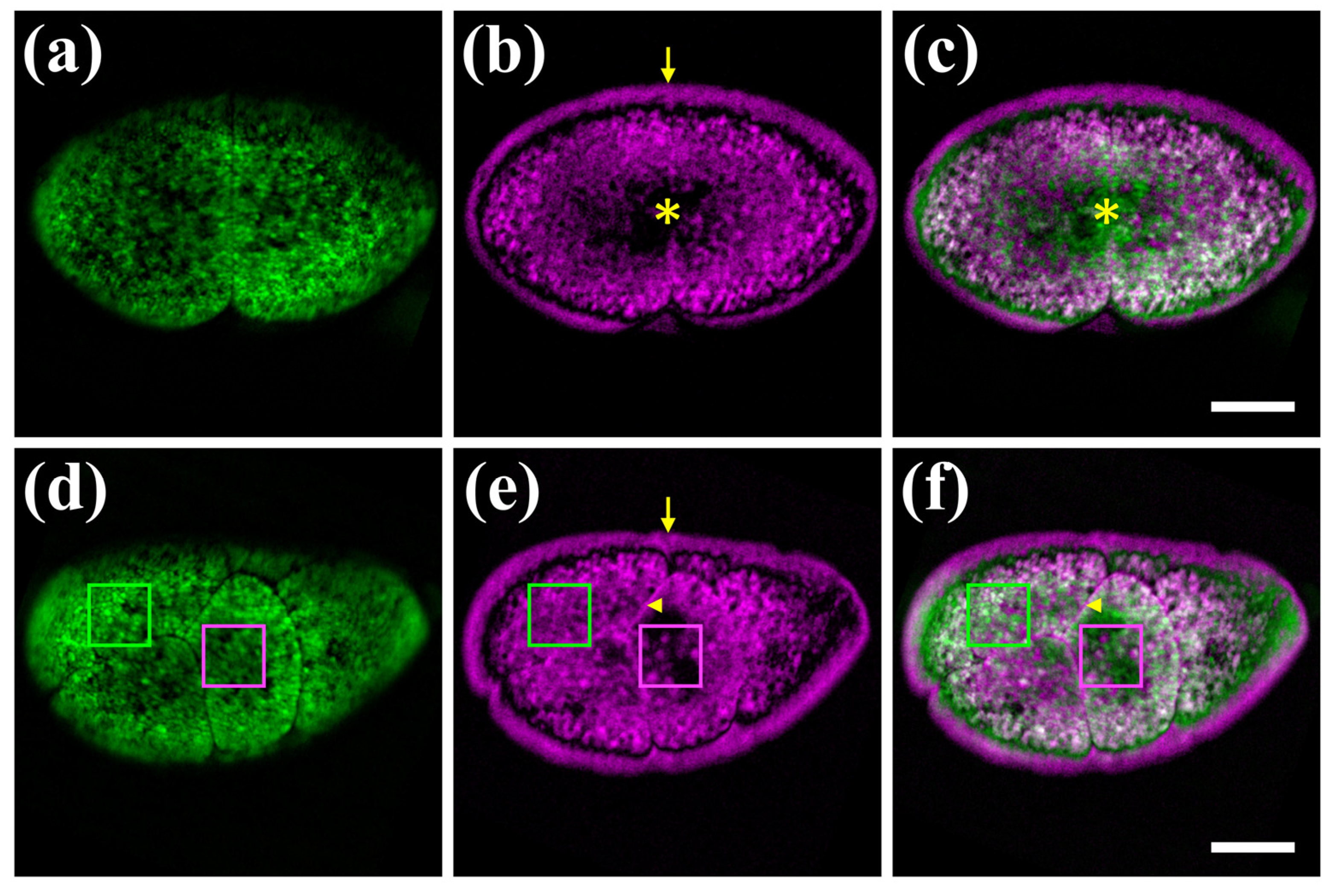
As a first application of our hybrid microscope, we imaged label-free fertilized Parhyale eggs with the 488 nm laser (Figure 3) as this excitation wavelength generated both strong PA and autofluorescence signals. Parhyale eggs are surrounded by a transparent eggshell, they are filled with yolk and undergo a stereotypic series of cell divisions (cleavages) after fertilization [25]. Unlabelled embryos exhibit a strong signal, primarily due to the autofluorescence of the yolk. Autofluorescence is detected in the entire space of the yolk-rich cells (blastomeres) produced at early cleavage stages (Figure 3a,d).
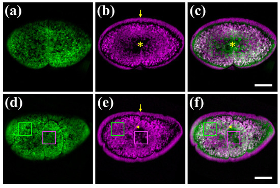
Figure 3.
Hybrid imaging of unlabelled Parhyale embryos. (a–c) Embryo at the 2-cell stage (stage S2 according to [25]). (d–f) Embryo at a later cleavage stage S5. Left panels (a,d) show the autofluorescence signal in green, the middle panels (b,e) show the PA signal in magenta, and the right panels (c,f) show the merged images. Asterisks indicate the yolk-free protoplasmic region, arrowheads the cell membranes, and arrows the outer eggshell mirroring the adjoining embryonic PA signal. Green and magenta boxes indicate yolk granules displaying differential autofluorescence and PA signals, respectively. Scale bars are 100 μm.
In accordance with previous findings using the FDPA microscope [22], a strong PA signal is also detected in the yolk at different stages of Parhyale embryogenesis (Figure 3b,e). Besides the overall similarities, a number of notable differences are detected between the emitted autofluorescence and PA signals (Figure 3c,f). First, the opaque yolk restricts light penetration and emission to the outer yolky surface (Figure 3a), while the PA signal reveals the deeper organization of the blastomeres with the yolk surrounding the yolk-free protoplasm (cytoplasm and nucleus) in the centre (Figure 3b,c). Second, a remarkable PA artefact is produced at the periphery of the egg. The minuscule distance between the embryo and eggshell, which is not visible in fluorescent images (Figure 3a,d), appears as a large gap in the PA images, and the peripheral PA signal is mirrored on the eggshell (Figure 3b,e). The enhanced PA contrast in the eggshell could be attributed to interference effects of the generated single-frequency PA waves, following their multiple reflections on the eggshell-embryo interface, as a result of the distinct mechanical properties between the two biological media. Third, the cell membranes are detected through PA signals, but not optically (Figure 3d–f). Finally, among yolk granules, there are particles detected with both methods and others exhibiting either autofluorescence or PA signal (Figure 3d–f). To quantify the degree of contrast complementarity between the two microscopy modalities, we have estimated the Pearson’s correlation coefficient R for the autofluorescence and PA images shown in Figure 3. In the case of the 2-cell embryo (Figure 3a–c), R was equal to 0.279, whereas for the later cleavage stage specimen (Figure 3d–f), the respective value was found at 0.322, indicating a weak correlation between the images. We conclude that the integration of PA and autofluorescene confocal microscopy can extract both overlapping and distinct information from unlabelled live Parhyale embryos.
3.3. Hybrid Imaging of Fluorescently Labelled Parhyale hawaiensis Embryos
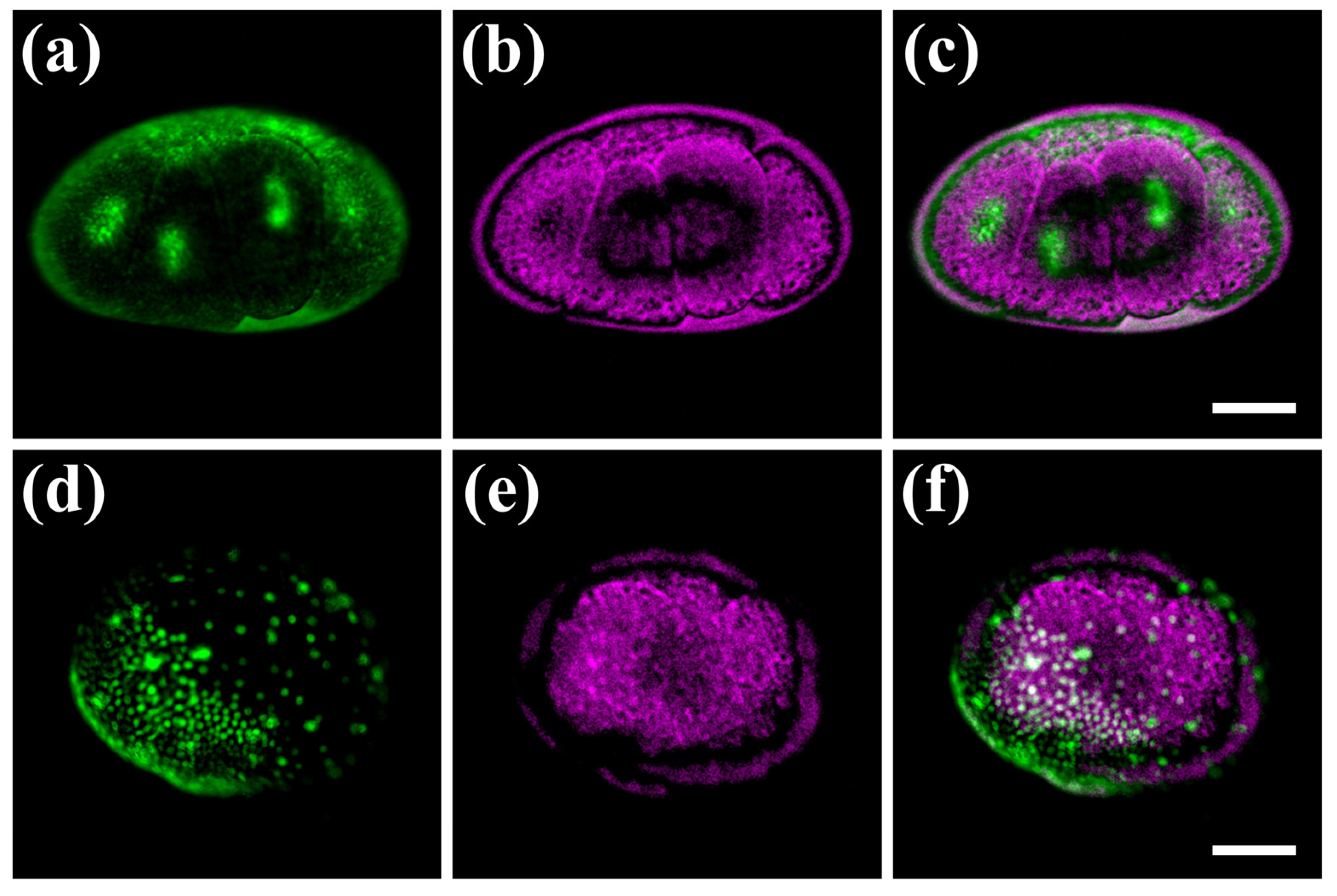
We next tested the performance of our hybrid microscope on chemically and genetically labelled fluorescent Parhyale embryos. To reduce the strong autofluorescence produced with the 488 nm laser, these experiments were performed using the 532 nm laser line, which is also closer to the absorption peak of the fluorescent labels. Cleavage stage embryos labelled with the permeant SYTO® 24 green dye exhibited a strong and localized fluorescence signal in the nuclei of blastomeres, and reduced autofluorescence in the surrounding yolk (Figure 4a). These observations have been verified by independent widefield fluorescence measurements using a commercial imaging instrument.
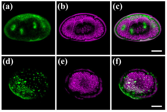
Figure 4.
Hybrid imaging of fluorescently labelled Parhyale embryos. (a–c) Embryo at the cleavage stage S5. (d–f) Embryo at mid-germband stage S14. Left panels (a,d) show the nuclear fluorescent signal in green, middle panels (b,e) show the PA signal in magenta, and right panels (c,f) show the merged images. In panels (d,f), the densely packed nuclei in the anterior-ventral region and the scattered nuclei in the posterior-dorsal region correspond to the embryonic and extra-embryonic parts of the embryo, respectively. Scale bars are 100 μm.
The yolk, membranes and eggshell of SYTO® 24-labelled embryos exhibited a strong PA signal (similar to unlabelled embryos) resulting in the imaging of distinct, complementary cellular compartments in this case (Figure 4b,c). In later germband stages, about 3 days after fertilization, all nuclei were fluorescently labelled by genetic means using a heat-inducible monomeric red fluorescent protein coupled to histone H2B (Figure 4d). The fluorescent embryonic and extra-embryonic parts of Parhyale were spread around the egg surface, sandwiched between the central yolk mass and the outer eggshell visible with the PA imaging modality (Figure 4e,f). Similarly to the previous case of unlabelled embryos, we estimated the R values for the two specimens shown in Figure 4a–c and Figure 4d–f at 0.005 and 0.133, respectively, revealing a negligible fluorescence and PA signal correlation, and thus a very high contrast complementarity degree. Thus, our hybrid microscope enables us to image cells and tissues simultaneously in vivo using specific fluorescent labels according to the researcher’s needs, as well as, their dynamic interactions with other fundamental but understudied egg components such as the yolk and the eggshell, which can be visualized with PA but not with optical methods.
4. Discussion and Conclusions
The exceptional capabilities offered by PA microscopy have recently established its strong potential, predominantly in the field of biomedical studies [27,28,29], also finding alternative interesting applications in other research branches, including forensic science [30] and cultural heritage diagnostics [31,32,33]. In particular, the high transmissivity of PA signals in turbid media, the excellent optical absorption sensitivity, and the scalable spatial resolution according to the optical or acoustic diffraction-limited focus have enabled the detailed acquisition of valuable molecular, anatomical and functional information deep inside scattering tissues, following the excitation of intrinsic chromophores (e.g., melanin, hemoglobin) or exogenous agents such as nanoparticles and dyes [28].
Aiming at the delivery of complementary contrast in biological tissues, several studies have demonstrated the development of multimodal instruments, effectively combining time-domain (TD) PA microscopy with well-established optical diagnostic techniques such as confocal fluorescence microscopy, multiphoton imaging and optical coherence tomography (OCT) [34]. It is worth mentioning that these hybrid imaging developments have found various significant applications, including the sensitive detection of capillary blood vessels in mice [35,36,37,38], the delineation of ocular anatomy [39,40,41], the investigation of zebrafish larvae [42,43], the measurement of melanin content in fish scales [44] as well as the spatial mapping of pigments in vegetative tissues [45]. Nevertheless, all the aforementioned experimental configurations have integrated expensive nanosecond Q-switched laser sources for the efficient excitation of PA signals, restricting significantly the wider accessibility of the hybrid imaging methods by many biological laboratories. On top of this, as generated PA waves are detected in the TD, high-speed DAQ cards are additionally required for signal digitization and recording, further increasing the microscope’s total cost. To overcome the budget constraints of hybrid instruments incorporating PA and optical modalities, an FDPA and fluorescence microscopy system has been recently proposed as an alternative and cost-effective solution for obtaining label-free complementary information [46]. The system employed mechanical raster scanning for image acquisition, a needle hydrophone and an avalanche photodiode for PA and luminescence detection, respectively, and two lock-in amplifiers for the determination of signal amplitude. The time required for a 101 × 101-pixel image was around 5 min and the scanning region was limited to 60 by 60 μm2, whereas the integration of lock-in detection instead of I/Q demodulation significantly raised the total cost of the microscope. While this interesting proof-of-concept study marginally reported the promising capabilities of such an approach in red blood cells, it did not uncover the full potential of the hybrid microscope in the context of a real-world biological application requiring demanding high-resolution in vivo observations. Furthermore, the study did not compensate for reconstruction artifacts due to the apparent interference of the emitted single-frequency PA wavefronts across the finite surface of the ultrasonic detector which hindered the recording of reliable optical absorption images, as in the case of conventional TDPA microscopy [23,47]. Finally, another study has combined FDPA microscopy with multiphoton techniques in a multimodal instrument [48], though utilizing sequential scans with two different laser beams for the excitation of the signals. Despite the fact that this imaging approach demonstrated a remarkable contrast complementarity that can be achieved in thin soft tissues in vivo (e.g., mouse ears), it was neither inherently hybrid nor cost-efficient, as it required the integration of an expensive femtosecond laser source.
In this work, we have presented the development of an inexpensive optimized hybrid microscopy platform integrating confocal fluorescence and FDPA contrast modes, for the imaging of different developmental stages in live Parhyale embryos. The important difference of the presented system compared to previously published systems [22,23] is the development and integration of the FDPA contrast modality with a synchronous confocal fluorescence detection path, providing highly complementary and valuable diagnostic information. This upgraded microscope operates in an inherently hybrid mode, as it is capable of exciting and detecting simultaneously fluorescence and PA signals arising from radiative and radiationless molecular relaxations, respectively. The transformation of the FD-PAM system into a hybrid contrast instrument required several crucial additions, modifications and adjustments in the microscope’s optical, optomechanical and electronic components, such as the incorporation of appropriate lenses, filters, optical telescopes, precision translational stages, PMTs and amplifiers. It also required the development of new customized software for the fully synchronized recording of two signals entirely different in nature (fluorescence light and single-frequency ultrasound). Our first PA system [23], was actually not optimized regarding PA detection because the selected modulation frequency was set at 10 MHz, whereas the nominal central frequency of the transducer is at 20 MHz, resulting in heavily reduced sensitivity. The configuration presented here for PA imaging was upgraded as previously described [22], and has substantially improved image quality and spatial resolution. The total cost of the development of this hybrid microscope has been estimated at USD 20.000, which is approximately one third of the required budget for a conventional TDPA microscope. It should be noted that FDPA microscopy can only provide amplitude images without any depth resolution, due to the use of one modulation frequency. On the contrary, TD approaches employ pulsed irradiation to excite broadband PA waves, providing an axial resolution in the order of ~10 μm [28]. Furthermore, FDPA microscopes are known to provide considerably lower SNR values than their TD counterparts, which can be up to two orders of magnitude smaller for similar optical energy deposition levels [46].
We have initially characterized the temporal characteristics of intensity-modulated laser beams at 488 and 532 nm, evaluating the modulation depth and the amplitude/power ratios of the fundamental excitation frequency with respect to the second and third harmonic components. The estimated parameters were indicative of a highly efficient PA excitation scheme, as the vast majority of the deposited optical energy would induce the generation of ultrasonic waves with a frequency equal to the sensitivity peak of the employed transducer at 9.5 MHz. In addition, we have assessed the lateral resolution of the system through the confocal imaging of fluorescent nanobeads, and found a slightly worse performance than the predicted optical diffraction-limited values. The extracted degree of detail (~1.5 μm), though, has been proven sufficient for the high-resolution visualization of the most important structural features of early and later stage Parhyale embryos. Furthermore, the application of the reconstruction principles formulated in a previous study [23] has allowed for the generation of MAP PA images which are directly comparable to respective results obtained through TDPA microscopes, providing quantified optical absorption information of the investigated specimens. In this manner, the FDPA modality was able to image the yolk’s distribution and the membranes of the embryonic cells based exclusively on their intrinsic absorption properties, whereas the location of cells’ nuclei was clearly visible through confocal microscopy and the use of specific fluorescent tags. Finally, under label-free conditions, the autofluorescence of the specimens could additionally reveal the structure of each embryonic cell during early embryogenesis stages. Although the nature of the observed autofluorescent granules is still unknown, our hybrid microscope provides an excellent tool to explore and distinguish these valuable intrinsic biomarkers in the future. It has to be stressed that (a) the totally different physical mechanisms governing signal formation (PA/autofluorescence), (b) the qualitative evaluation and comparison of the images (see the green and magenta boxes of Figure 3d–f), and finally (c) the quantitative assessment of image correlation through the calculation of Pearson’s coefficient R, indicate undoubtedly that PA and autofluorescence images provide distinct biological information in unlabelled Parhyale embryos.
The aforementioned findings demonstrate explicitly the suitability of the proposed hybrid imaging methodology for the detailed in vivo investigation of Parhyale development, offering highly complementary contrast in both fluorescently stained and unlabelled embryos. We have to point out that PA signals offer a significantly higher transmissivity than optical signals, as the attenuation coefficient of ultrasonic waves can be up to three orders of magnitude lower than light [49]. This very important property of PA waves enables investigations at higher imaging depths than traditional fluorescence-based modalities. Furthermore, the transmission of the 9.5 MHz PA waves through the Parhyale embryos is not expected to influence the recording of the signals significantly. In the case of soft tissues, the average attenuation coefficient for ultrasonic waves at 9.5 MHz is in the order of 0.7 dB/mm [50], whereas the size of Parhyale embryos is less than 0.5 mm. Therefore, the ultrasonic attenuation through the specimen is estimated at around 0.35 dB, which can be considered quite negligible for the requirements of the present study. In particular, our system allows us to visualize the spatial relationships between specific fluorescent features (such as the nuclei of the embryonic and extraembryonic tissues) that are sandwiched between the nonfluorescent eggshell and yolk (Figure 4d–f). This is a prerequisite for modern, systems-level characterizations of development that have started revealing hitherto unknown interactions between tissues in vivo, such as the mechano-chemical interplay between embryonic and extraembryonic tissues and the surrounding eggshell during early embryogenesis. Similarly, we anticipate that the powerful combination of PA with fluorescence microscopy will enable us to investigate the unknown role that yolk plays in early cleavage and later organogenesis stages. In this context, we provide developmental biologists with a novel, powerful diagnostic tool that is capable of tracking the spatial distribution and the dynamic interactions of the yolk, with promising potential to unravel fundamental mechanisms linked to body plan and body part evolution.
The presented setup could be further upgraded through the integration of various CW laser sources emitting either in the UV or NIR spectral region, enabling the efficient PA excitation of various intrinsic tissue chromophores such as DNA/RNA or lipid depositions, as has been shown in the literature using standalone TDPA microscopes [51,52,53]. Lock-in detection of PA signals is also expected to improve the sensitivity of the system, thus minimizing the image acquisition time and the deposited optical energy on the embryo. With regard to the confocal modality, additional PMT modules may be utilized for the concurrent recording of different fluorescent labels, offering the capability of multicolor imaging.
In this study, we have used an objective lens with NA = 0.25, providing a balance between adequate depth of field (~20 μm) and good lateral resolution (~1.5 μm as calculated in Section 3.1). The pinhole size for the confocal modality is equal to 50 μm, offering a good experimental trade-off between high SNR values and sufficient optical sectioning capabilities. The beam expansion ratio is ~2.3×, to ensure the filling of the back aperture of the objective (exploiting thus its full NA) and a sufficiently large field of view, which can be up to 800 × 800 μm2. Finally, the selected modulation frequency at 9.5 MHz offers a good balance between high efficiency of PA signal generation and sufficient transmissivity of the PA waves through tissue. However, in case of specimens other than Parhyale embryos, the technical parameters of the hybrid microscope (e.g., the objective’s numerical aperture, pinhole size, beam expansion ratio and optical modulation frequency) have to be carefully adjusted according to their optical, geometrical and morphological properties as well as the required spatial resolution, depth of field and field of view. In the case of smaller samples, for example, the use of a higher objective’s NA is expected to be more beneficial, as it would provide improved lateral resolution (e.g., for NA = 1.4, it could be up to 200 nm) and shallower depths of field (~600 nm), at the cost, however, of a reduced field of view (~100 × 100 μm2). On the other hand, larger samples could be measured using lower NA values, for example in the order of 0.1, providing a worse lateral resolution (~2.5 μm) but a significantly larger depth of field and field of view with values approximately equal to 100 μm and 1.5 × 1.5 mm2, respectively. This optimization would expand the application potential of the proposed technique, allowing for substantially improved observations of various established model organisms in developmental studies, such as Drosophila melanogaster, Danio rerio, Xenopus tropicalis, mouse embryos and others. Therefore, we anticipate that the findings of the current study will pave the way for the broader adoption of inexpensive hybrid optical and PA diagnostic methods in developmental biology, significantly upgrading the imaging capabilities of the currently employed pure optical microscopy technologies.
Author Contributions
Conceptualization, G.Z. and G.J.T.; methodology, G.J.T.; software, G.J.T.; validation, G.J.T., I.L. and M.K.; formal analysis, G.J.T. and E.T.; investigation, G.J.T., I.L., M.K. and E.T.; resources, G.Z., A.P. and G.J.T.; data curation, G.J.T.; writing—original draft preparation, G.J.T. and A.P.; writing—review and editing, G.Z., A.P. and G.J.T.; visualization, G.J.T.; supervision, G.Z. and A.P.; project administration, G.Z. and A.P.; funding acquisition, G.Z. and A.P. All authors have read and agreed to the published version of the manuscript.
Funding
This research was funded by H2020 Laserlab Europe (grant number: EC-GA 871124), the H2020 FETOPEN project “DynAMic” (grant number: EC-GA-863203), the NSRF 2014–2020 “BIOIMAGING-GR” (grant number: MIS 5002755), “INNOVAPROTECT” (grant number: MIS 5030524) and FORTH Synergy project “ANILIMO”.
Data Availability Statement
The data that support the findings of this study are available from the corresponding author upon reasonable request.
Acknowledgments
G.J.T. and G.Z. wish to thank Orestis Faklaris from Institute Jacques Monod (now at Montpellier Cell Biology Research Center) for donating the microscope body used to develop the system of the study presented here.
Conflicts of Interest
The authors declare no conflict of interest.
References
- Irion, U.; Nüsslein-Volhard, C. Developmental genetics with model organisms. Proc. Natl. Acad. Sci. USA 2022, 119, e2122148119. [Google Scholar] [CrossRef] [PubMed]
- Rallis, J.; Kapai, G.; Pavlopoulos, A. Chapter 16—Parhyale hawaiensis, Crustacea. In Handbook of Marine Model Organisms in Experimental Biology: Established and Emerging; Boutet, A., Schierwater, B., Eds.; CRC Press: Boca Raton, FL, USA, 2021. [Google Scholar]
- Paris, M.; Wolff, C.; Patel, N.H.; Averof, M. The crustacean model parhyale hawaiensis. Curr. Top. Dev. Biol. 2022, 147, 199–230. [Google Scholar] [PubMed]
- Pavlopoulos, A.; Kontarakis, Z.; Liubicich, D.M.; Serano, J.M.; Akam, M.; Patel, N.H.; Averof, M. Probing the evolution of appendage specialization by hox gene misexpression in an emerging model crustacean. Proc. Natl. Acad. Sci. USA 2009, 106, 13897–13902. [Google Scholar] [CrossRef]
- Martin, A.; Serano, J.M.; Jarvis, E.; Bruce, H.S.; Wang, J.; Ray, S.; Barker, C.A.; O’Connell, L.C.; Patel, N.H. CRISPR/Cas9 mutagenesis reveals versatile roles of hox genes in crustacean limb specification and evolution. Curr. Biol. 2016, 26, 14–26. [Google Scholar] [CrossRef] [PubMed]
- Bruce, H.S.; Patel, N.H. Knockout of crustacean leg patterning genes suggests that insect wings and body walls evolved from ancient leg segments. Nat. Ecol. Evol. 2020, 4, 1703–1712. [Google Scholar] [PubMed]
- Clark-Hachtel, C.M.; Tomoyasu, Y. Two sets of candidate crustacean wing homologues and their implication for the origin of insect wings. Nat. Ecol. Evol. 2020, 4, 1694–1702. [Google Scholar] [CrossRef]
- Bruce, H.S.; Patel, N.H. The daphnia carapace and other novel structures evolved via the cryptic persistence of serial homologs. Cur. Biol. 2022, 32, 3792–3799.e3. [Google Scholar] [CrossRef] [PubMed]
- Price, A.L.; Modrell, M.S.; Hannibal, R.L.; Patel, N.H. Mesoderm and ectoderm lineages in the crustacean parhyale hawaiensis display intra-germ layer compensation. Dev. Biol. 2010, 341, 256–266. [Google Scholar] [CrossRef][Green Version]
- Alwes, F.; Hinchen, B.; Extavour, C.G. Patterns of cell lineage, movement, and migration from germ layer specification to gastrulation in the amphipod crustacean parhyale hawaiensis. Dev. Biol. 2011, 359, 110–123. [Google Scholar] [CrossRef]
- Chaw, R.C.; Patel, N.H. Independent migration of cell populations in the early gastrulation of the amphipod crustacean Parhyale hawaiensis. Dev. Biol. 2012, 371, 94–109. [Google Scholar] [CrossRef]
- Wolff, C.; Tinevez, J.-Y.; Pietzsch, T.; Stamataki, E.; Harich, B.; Guignard, L.; Preibisch, S.; Shorte, S.; Keller, P.J.; Tomancak, P.; et al. Multi-view light-sheet imaging and tracking with the MaMuT software reveals the cell lineage of a direct developing arthropod limb. eLife 2018, 7, e34410. [Google Scholar] [CrossRef] [PubMed]
- Ramos, A.P.; Gustafsson, O.; Labert, N.; Salecker, I.; Nilsson, D.-E.; Averof, M. Analysis of the genetically tractable crustacean Parhyale hawaiensis reveals the organisation of a sensory system for low-resolution vision. BMC Biol. 2019, 17, 67. [Google Scholar] [CrossRef] [PubMed]
- Konstantinides, N.; Averof, M. A common cellular basis for muscle regeneration in arthropods and vertebrates. Science 2014, 343, 788–791. [Google Scholar] [CrossRef] [PubMed]
- Alwes, F.; Enjolras, C.; Averof, M. Live imaging reveals the progenitors and cell dynamics of limb regeneration. eLife 2016, 5, e19766. [Google Scholar] [CrossRef]
- Pavlopoulos, A.; Wolff, C. Crustacean limb morphogenesis during normal development and regeneration. In The Natural History of the Crustacea: Developmental Biology and Larval Ecology; Anger, K., Harzsch, S., Thiel, M., Eds.; Oxford University Press: Oxford, UK, 2020. [Google Scholar]
- Almazán, A.; Çevrim, Ç.; Musser, J.M.; Averof, M.; Paris, M. Crustacean leg regeneration restores complex microanatomy and cell diversity. Sci. Adv. 2022, 8, eabn9823. [Google Scholar] [CrossRef]
- Gerberding, M.; Browne, W.E.; Patel, N.H. Cell lineage analysis of the amphipod crustacean parhyale hawaiensis reveals an early restriction of cell fates. Development 2002, 129, 5789–5801. [Google Scholar] [CrossRef]
- Serano, J.M.; Martin, A.; Liubicich, D.M.; Jarvis, E.; Bruce, H.S.; La, K.; Browne, W.E.; Grimwood, J.; Patel, N.H. Comprehen-sive analysis of hox gene expression in the amphipod crustacean parhyale hawaiensis. Dev. Biol. 2016, 409, 297–309. [Google Scholar] [CrossRef]
- Kao, D.; Lai, A.G.; Stamataki, E.; Rosic, S.; Konstantinides, N.; Jarvis, E.; Di Donfrancesco, A.; Pouchkina-Stancheva, N.; Sémon, M.; Grillo, M.; et al. The genome of the crustacean parhyale hawaiensis, a model for animal development, regeneration, immunity and lignocellulose digestion. eLife 2016, 5, e20062. [Google Scholar] [CrossRef]
- Sugawara, K.; Çevrim, Ç.; Averof, M. Tracking cell lineages in 3D by incremental deep learning. eLife 2022, 11, e69380. [Google Scholar] [CrossRef]
- Tserevelakis, G.J.; Velentza, S.; Liaskas, I.; Archontidis, T.; Pavlopoulos, A.; Zacharakis, G. Imaging parhyale hawaiensis embryogenesis with frequency domain photoacoustic microscopy: A novel tool in developmental biology. J. Biophotonics 2022, 15, e202200202. [Google Scholar] [CrossRef]
- Tserevelakis, G.J.; Mavrakis, K.G.; Kakakios, N.; Zacharakis, G. Full image reconstruction in frequency-domain photoacoustic microscopy by means of a low-cost I/Q demodulator. Opt. Lett. 2021, 46, 4718–4721. [Google Scholar] [CrossRef]
- Kontarakis, Z.; Pavlopoulos, A. Transgenesis in non-model organisms: The case of Parhyale. Methods Mol. Biol. 2014, 1196, 145–181. [Google Scholar]
- Browne, W.E.; Price, A.L.; Gerberding, M.; Patel, N.H. Stages of embryonic development in the amphipod crustacean, parhyale hawaiensis. Genesis 2005, 42, 124–149. [Google Scholar] [CrossRef]
- Tserevelakis, G.J.; Soliman, D.; Omar, M.; Ntziachristos, V. Hybrid multiphoton and optoacoustic microscope. Opt. Lett. 2014, 39, 1819–1822. [Google Scholar] [CrossRef]
- Yao, J.; Wang, L.V. Sensitivity of photoacoustic microscopy. Photoacoustics 2014, 2, 87–101. [Google Scholar] [CrossRef]
- Yao, J.; Wang, L.V. Photoacoustic microscopy. Laser Photonics Rev. 2013, 7, 758–778. [Google Scholar] [CrossRef]
- Jeon, S.; Kim, J.; Lee, D.; Baik, J.W.; Kim, C. Review on practical photoacoustic microscopy. Photoacoustics 2019, 15, 100141. [Google Scholar]
- Suzuki, M.; Kikushima, H.; Kashihara, W.; Suzuki, T. Photoacoustic imaging to examine documents altered by black pens on paper in forensic science. Opt. Eng. 2020, 59, 034106. [Google Scholar] [CrossRef]
- Tserevelakis, G.J.; Siozos, P.; Papanikolaou, A.; Melessanaki, K.; Zacharakis, G. Non-invasive photoacoustic detection of hidden underdrawings in paintings using air-coupled transducers. Ultrasonics 2019, 98, 94–98. [Google Scholar] [CrossRef]
- Tserevelakis, G.J.; Tsagkaraki, M.; Siozos, P.; Zacharakis, G. Uncovering the hidden content of layered documents by means of photoacoustic imaging. Strain 2019, 55, e12289. [Google Scholar] [CrossRef]
- Tserevelakis, G.J.; Pouli, P.; Zacharakis, G. Listening to laser light interactions with objects of art: A novel photoacoustic approach for diagnosis and monitoring of laser cleaning interventions. Herit. Sci. 2020, 8, 98. [Google Scholar] [CrossRef]
- Dadkhah, A.; Jiao, S. Integrating photoacoustic microscopy with other imaging technologies for multimodal imaging. Exp. Biol. Med. 2021, 246, 771–777. [Google Scholar]
- Rao, B.; Soto, F.; Kerschensteiner, D.; Wang, L.V. Integrated photoacoustic, confocal, and two-photon microscope. J. Biomed. Opt. 2014, 19, 036002. [Google Scholar] [CrossRef] [PubMed]
- Wang, Y.; Maslov, K.; Kim, C.; Hu, S.; Wang, L.V. Integrated photoacoustic and fluorescence confocal microscopy. IEEE Trans. Biomed. Eng. 2010, 57, 2576–2578. [Google Scholar] [CrossRef] [PubMed]
- Park, J.; Park, B.; Kim, T.Y.; Jung, S.; Choi, W.J.; Ahn, J.; Yoon, D.H.; Kim, J.; Jeon, S.; Lee, D.; et al. Quadruple ultrasound, photoacoustic, optical coherence, and fluorescence fusion imaging with a transparent ultrasound transducer. Proc. Natl. Acad. Sci. USA 2021, 118, e1920879118. [Google Scholar] [CrossRef]
- Dadkhah, A.; Zhou, J.; Yeasmin, N.; Jiao, S. Integrated multimodal photoacoustic microscopy with OCT-guided dynamic focusing. Biomed Opt. Express 2019, 10, 137–150. [Google Scholar] [PubMed]
- Zhang, W.; Li, Y.; Yu, Y.; Derouin, K.; Qinm, Y.; Nguyenm, V.P.; Xia, X.; Wang, X.; Paulus, Y.M. Simultaneous photoacoustic microscopy, spectral-domain optical coherence tomography, and fluorescein microscopy multi-modality retinal imaging. Photoacoustics 2020, 20, 100194. [Google Scholar]
- Tserevelakis, G.J.; Avtzi, S.; Tsilimbaris, M.K.; Zacharakis, G. Delineating the anatomy of the ciliary body using hybrid optical and photoacoustic imaging. J. Biomed. Opt. 2017, 22, 060501. [Google Scholar] [CrossRef]
- Tserevelakis, G.J.; Mavrakis, K.G.; Pantazopoulou, D.; Lagoudaki, E.; Detorakis, E.; Zacharakis, G. Hybrid autofluorescence and photoacoustic label-free microscopy for the investigation and identification of malignancies in ocular biopsies. Opt. Lett. 2020, 45, 5748–5751. [Google Scholar]
- Hosseinaee, Z.; Tummon Simmons, J.A.; Reza, P.H. Dual-modal photoacoustic imaging and optical coherence tomography. Front. Phys. 2020, 8, 616618. [Google Scholar]
- Soliman, D.; Tserevelakis, G.J.; Omar, M.; Ntziachristos, V. Combining microscopy with mesoscopy using optical and optoacoustic label-free modes. Sci. Rep. 2015, 5, 12902. [Google Scholar] [CrossRef] [PubMed]
- Tserevelakis, G.J.; Pavlidis, M.; Samaras, A.; Barmparis, G.D.; Mavrakis, K.G.; Draganidis, I.; Oikonomou, A.; Fanouraki, E.; Tsironis, G.P.; Zacharakis, G. Hybrid confocal fluorescence and photoacoustic microscopy for the label-free investigation of melanin accumulation in fish scales. Sci. Rep. 2022, 12, 7173. [Google Scholar] [CrossRef] [PubMed]
- Tserevelakis, G.J.; Tsagkaraki, M.; Zacharakis, G. Hybrid photoacoustic and optical imaging of pigments in vegetative tissues. J. Microsc. 2016, 263, 300–306. [Google Scholar] [CrossRef]
- Langer, G.; Buchegger, B.; Jacak, J.; Klar, T.A.; Berer, T. Frequency domain photoacoustic and fluorescence microscopy. Biomed. Opt. Expr. 2016, 7, 2692–2702. [Google Scholar] [CrossRef]
- Tserevelakis, G.J.; Zacharakis, G. High precision photoacoustic interferometer for the determination of the speed of sound in liquid media. Opt. Expr. 2022, 30, 28559–28568. [Google Scholar] [CrossRef]
- Kellnberger, S.; Soliman, D.; Tserevelakis, G.J.; Seeger, M.; Yang, H.; Karlas, A.; Prade, L.; Omar, M.; Ntziachristos, V. Optoacoustic microscopy at multiple discrete frequencies. Light Sci. Appl. 2018, 7, 109. [Google Scholar] [CrossRef]
- Hui, J.; Li, R.; Phillips, E.H.; Goergen, C.J.; Sturek, M.; Cheng, J.-X. Bond-selective photoacoustic imaging by converting molecular vibration into acoustic waves. Photoacoustics 2016, 4, 11–21. [Google Scholar] [CrossRef]
- Shankar, H.; Pagel, P.S.; Warner, D.S. Potential adverse ultrasound-related biological effects: A critical review. Anesthesiology 2011, 115, 1109–1124. [Google Scholar] [CrossRef]
- Yao, D.-K.; Maslov, K.; Shung, K.K.; Zhou, Q.; Wang, L.V. In vivo label-free photoacoustic microscopy of cell nuclei by excitation of DNA and RNA. Opt. Lett. 2010, 35, 4139–4141. [Google Scholar] [CrossRef]
- Dasa, M.K.; Nteroli, G.; Bowen, P.; Messa, G.; Feng, Y.; Petersen, C.R.; Koutsikou, S.; Bondu, M.; Moselund, P.M.; Podoleanu, A.; et al. All-fibre supercontinuum laser for in vivo multispectral photoacoustic microscopy of lipids in the extended near-infrared region. Photoacoustics 2020, 18, 100163. [Google Scholar] [CrossRef]
- Buma, T.; Conley, N.C.; Choi, S.W. Multispectral photoacoustic microscopy of lipids using a pulsed supercontinuum laser. Biomed. Opt. Expr. 2018, 9, 276–288. [Google Scholar] [CrossRef] [PubMed]
Disclaimer/Publisher’s Note: The statements, opinions and data contained in all publications are solely those of the individual author(s) and contributor(s) and not of MDPI and/or the editor(s). MDPI and/or the editor(s) disclaim responsibility for any injury to people or property resulting from any ideas, methods, instructions or products referred to in the content. |
© 2023 by the authors. Licensee MDPI, Basel, Switzerland. This article is an open access article distributed under the terms and conditions of the Creative Commons Attribution (CC BY) license (https://creativecommons.org/licenses/by/4.0/).

