1. Error in Table/Figure
In the original publication [1], Table 1 is reformatted because the numbers in the center column look dislocated from the numbers in the adjacent columns. Additionally, some units of Latin symbol (m) should be Greek symbol (μ), and these font errors are corrected. The corrections are highlighted.

Table 1.
Requirements for focus adjustment and beam alignment.
In the original publication [1], the fonts were corrupted in Figure 12 as published. The corrected Figure 12 appears below.
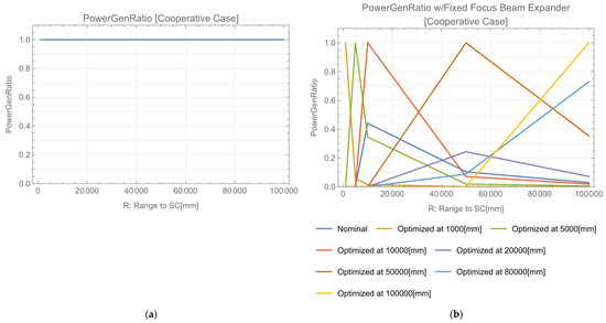
Figure 12.
Range dependence of power generation ratio (Cooperative OWPT). (a) When the focus is adjusted for each R, the power generation ratio is stably maintained at 100%; (b) There is a large variation in the power generation ratio for the range from 0 m to 100 m in case where the focus is optimized and fixed at specific range.
2. Text Correction
There were font errors in the original publication. The font of some symbols (m, D) is corrected to Greek font (μ, Δ). Corrections have been made to the paragraphs below, and they are highlighted.
4.3. Requirement for Focus Adjustment (Beam Size Control), Paragraph1:
To control the beam size to accommodate the solar cell array module size, (de) focusing the control of the beam expander is necessary. Its accuracy requirement would strongly affect the feasibility and cost of the system. In this section, the X and Y direction focus adjustment accuracy requirements are investigated based on the power generation ratio. Figure 4 shows the sensitivity analysis of the power generation ratio for focus adjustment errors with various positions (L) of the array. Assume the power generation ratio to be more than 80%; the requirement for focus adjustment depends on L, e.g., less than 2.3 mm (L = 1 m), 76 μm (L = 10 m), or 1.2 μm (L = 100 m). When the X-focus error is increased from zero in each plot, the size of the incident beam in the X direction decreases, and then, the beam becomes focused. The beam size increases again after the focus point with additional increases in the error. With an increase in beam size, the power generation ratio increases again and has its second peak. Such peaks are seen in each plot in Figure 4. The details of the power generation ratio simulation, including focus perturbation, are summarized in Appendix C.
4.3. Requirement for Focus Adjustment (Beam Size Control), Paragraph2:
Similar requirements were obtained for the Y direction (Figure 5). Similar peaks in the power generation ratio were observed to those in Figure 4. Determined at an 80% power generation ratio, the requirements for focus adjustment are, e.g., less than 1.32 mm (L = 1 m), 132 μm (L = 10 m), or 1.2 μm (L = 100 m).
4.4. Requirement for Beam Alignment, Paragraph2:
The beam propagates toward the center of the solar cell array; then, the power generation ratio is calculated with beam deviation along the X direction, which means rotation around the Y-axis (Figure 8). Determined at an 80% power generation ratio, the requirements for beam deviation along the X direction are, e.g., less than 2.21 mrad (L = 1 m), 149 μrad (L = 10 m), or 11.7 μrad (L = 100 m).
4.4. Requirement for Beam Alignment, Paragraph3:
Similarly, the power generation ratio for the Y direction beam deviation, which is rotation around the X-axis, was calculated (Figure 9). Determined at an 80% power generation ratio, the requirements for the beam deviation along the Y direction are, e.g., less than 2.51 mrad (L = 1 m), 631 μrad (L = 10 m), or 57.5 μrad (L = 100 m).
4.4. Requirement for Beam Alignment, Paragraph5:
Requirement for X, Y-direction deviation is quite strong. Assume their maximum angular control range is ±π/2 radian. Necessary resolution would be 2000 to 5000 in L < 10 m, 8000–80,000 in L < 30 m, 2 × 10⁵–8 × 10⁵ in 40 < L < 100 m. Resolution of 2000 to 5000 in L < 10 m would be feasible by single mechanism. However, there needs quite accurate single mechanism or a complex combination of various single mechanism for L > 10 m.
5.2. Requirement for Focus Adjustment, Paragraph1:
The requirement for range-dependent focus control accuracy was investigated (Figure 13). The requirements for beam rotation around the optical axis are, e.g., less than 3.5 mm (R = 1 m), 350 μm (R = 10 m), or 39 μm (R = 100 m).
5.3. Requirement for Beam Alignment, Paragraph1:
Figure 15 shows the power generation ratio calculation with the X direction alignment error (beam deviation). The requirements for the beam deviation in the X direction are, e.g., less than 6.9 mrad (R = 1 m), 0.8 mrad (R = 10 m), or 69 μrad (R = 100 m).
7.2 Precise Alignment Phase, Paragraph 3
The tilt angle of the array against the beam direction is detectable using the image sensor. Apparent angler size of the array with tilt angle θ at range L is , here lSC is size of the array. To detect decrease of apparent angler size of the array from θ = 0, it should be larger than image sensor’s accuracy 0.1 mrad. This means that . When lSC = 10 cm and L = 100 m, detection limit is θ = 451 mrad, which is less than the requirement (645 mrad). Even though 451 mrad itself is marginal for the requirement, using a zoom lens improves detection for longer L values. The transmitter requests the array to adjust its attitude, which corresponds to other 2 DoF.
Appendix C. Power Generation Ratio Calculation Including Perturbations, Appendix C.1. Focus Perturbation, Paragraph1:
Assume Δx opt and Δy opt give the optimum of the power generation ratio in the X and Y directions’ focus. Additional focus perturbations Δ′x, Δ′y are introduced to estimate the requirement for focus adjustment with replacements and .
The authors state that the scientific conclusions are unaffected. This correction was approved by the Academic Editor. The original publication has also been updated.
Reference
- Asaba, K.; Miyamoto, T. System Level Requirement Analysis of Beam Alignment and Shaping for Optical Wireless Power Transmission System by Semi–Empirical Simulation. Photonics 2022, 9, 452. [Google Scholar] [CrossRef]

Disclaimer/Publisher’s Note: The statements, opinions and data contained in all publications are solely those of the individual author(s) and contributor(s) and not of MDPI and/or the editor(s). MDPI and/or the editor(s) disclaim responsibility for any injury to people or property resulting from any ideas, methods, instructions or products referred to in the content. |
© 2023 by the authors. Licensee MDPI, Basel, Switzerland. This article is an open access article distributed under the terms and conditions of the Creative Commons Attribution (CC BY) license (https://creativecommons.org/licenses/by/4.0/).