Article

Spin-Hall Effect of Cylindrical Vector Vortex Beams

1
Shanxi Center of Technology Innovation for Light Manipulations and Applications, School of Applied Science, Taiyuan University of Science and Technology, Taiyuan 030024, China
2
Department of Science, Taiyuan Institute of Technology, Taiyuan 030008, China
3
School of Physics, Zhejiang University, Hangzhou 310027, China
*
Author to whom correspondence should be addressed.
Photonics 2023, 10(12), 1356; https://doi.org/10.3390/photonics10121356
Submission received: 26 October 2023 / Revised: 30 November 2023 / Accepted: 6 December 2023 / Published: 8 December 2023
(This article belongs to the Special Issue Emerging Topics in Structured Light)

Abstract

:
Spin-Hall effect (SHE) of light is one of the main manifestations of the spin-orbit interaction of photons, and has been extensively studied for optical beams with homogeneous polarization. Here, we present a theoretical study of the SHE of cylindrical vector vortex beams (CVVBs) possessing inhomogeneous polarization. We derive the analytical expressions of the SHE of CVVBs reflected and refracted at a dielectric interface with radial and azimuthal polarization of incidence. The spin-dependent shifts of the SHE of light linearly depend on the topological charge of the CVVBs. In contrast to the conventional SHE of horizontally or vertically polarized beams, the SHE shifts of the CVVBs are asymmetrical when the topological charge is nonzero. This asymmetry results in the transverse Imbert–Fedorov (IF) shifts that are proportional to the topological charge. Furthermore, based on weak measurement, we propose an experimental scheme to enhance the SHE and related IF shifts with proper pre- and post-selection polarization states. Our results advance the study of the SHE of structured light and may find applications in SHE-based techniques such as precision measurement.

1. Introduction

Spin-Hall effect (SHE) of light is an optical analogy of SHE in electronic systems, where the spin-1 photons correspond to the spin-1/2 electrons and the refractive index gradient corresponds to the electric potential gradient [1,2]. The SHE of light manifests itself as the spin splitting of optical beams in light-matter interaction, and originates from the spin-orbit interaction of light, which describes the coupling between the spin and orbit angular momenta of photons [3]. This phenomenon typically occurs when optical beams are reflected and refracted at dielectric interfaces, and it produces the opposite transverse shifts of the two spin components, i.e., the right-handed circular polarization (RCP) and the left-handed circular polarization (LCP) [4,5,6]. The SHE of light has also been studied in a variety of physical systems including gradient-index media [7], uniaxial crystals [8], photonic crystals [9], random media [10], birefringent waveguides [11], metasurfaces [12,13], curved spacetimes [14], etc.
In general, the spin-dependent shift of the SHE of light is at the deep-subwavelength scale. To detect the effect, the weak-measurement technique, which can significantly amplify the tiny SHE shifts, is commonly used [15,16,17]. By incorporating the weak measurement, the SHE of light provides a precision metrological tool due to its sensitivity to variations in physical parameters of the interfaces, and has been used in probing nanoscale fluctuations of meta-atoms [18], precision measurement of optical conductivity [19], real-time detection of chemical reaction [20], and identifying graphene layers [21], to mention a few.
One of the most important features of the SHE is its sensitivity to the polarization of the incident beam. Most of the previous studies on the SHE of light have focused on homogeneous incidence polarization, especially on horizontal and vertical polarization [1,2]. However, there exists diverse structured light possessing complex inhomogeneous polarization [22,23]. An important example of such structured light with fundamental and practical interest is cylindrical vector vortex beams (CVVBs) [24,25], which can be generated by using spatial light modulators [26], space-variant subwavelength gratings [27], q-plates [28,29,30], metasurfaces [31,32], etc. The CVVBs are characterized by an axisymmetric polarization distribution and a helical phase factor e i l θ (l is an integer number) with a polarization and phase singularity that appears as an isolated dark spot and that possesses a topological charge of l [33]. The spatial phase and polarization freedoms of the CVVBs provide the possibility to process information in high-dimensional Hilbert spaces, enabling higher information capacity [34,35]. Due to these unique properties and the potential applications in the fields of optical communications [36], super-resolution imaging [37,38], particle trapping [39], and atomic compasses [40], the study of CVVBs has attracted enormous research interests over the past few years.
In this article, we focus on the theoretical study of the SHE of CVVBs. Although the SHE of vortex beams with homogeneous polarization has been studied extensively [1,2], little research has been conducted on the SHE of inhomogeneously polarized vortex beams such as CVVBs. Here, taking the radially polarized vortex beam (RVB) and the azimuthally polarized vortex beam (AVB) as two typical examples of CVVBs, we derive the analytical expressions of the SHE shifts of reflected and refracted beams at a dielectric interface. We find that the SHE shifts linearly depend on the topological charge of the incident beam. The opposite transverse shifts of the two spin components (RCP and LCP) of the reflected (refracted) beam exhibit asymmetry when the topological charge of the incident beam is nonzero. As a result, the reflected (refracted) beam undergoes an overall transverse shift, i.e., the Imbert–Fedorov (IF) shift [41], which is shown to be proportional to the topological charge. The calculated SHE and related IF shifts are a fraction of the wavelength. To amplify these shifts, we propose a weak-measurement scheme with proper pre- and post-selection polarization states, allowing the experimental detection of the effects. Our research could be extended to study the SHE of vector vortex beams with more complex inhomogeneous polarization [22], such as high-order CVVBs, high-order Poincaré sphere beams, etc. The previously reported SHE-based precision measurement schemes employ the homogeneously polarized beam without topological charge [18,19,20,21]. Utilizing vector vortex beams such as CVVBs in the SHE-based precision measurement could provide additional degrees of freedom beyond the incidence angle, e.g., topological charge, azimuthal order of polarization, etc., for estimating the physical quantity to be measured and thus might improve the accuracy of the measurement.

2. SHE of RVB and AVB

Figure 1 shows the schematic diagram of the SHE of light under consideration. The optical beam is reflected and refracted at a dielectric interface separating two isotropic media with the refractive indexes of n and n . Here, we consider the air-glass interface with n = 1 for air and n = 1.515 for BK7 glass at the wavelength of 632.8 nm (He-Ne laser). This configuration is often employed in the experimental studies on the SHE. Due to the spin-orbit interaction, the reflected (refracted) beam splits into its two spin components by opposite transverse SHE shifts δ r ( t ) , ± along the y-axis. If the SHE shifts are asymmetrical, i.e., | δ r ( t ) , + | | δ r ( t ) , | , as in the case of the RVB and AVB discussed below, the overall transverse IF shift δ r ( t ) , IF occurs. In addition, the reflected (refracted) beam also undergoes a longitudinal shift known as the Goos–Hänchen shift [41], which is out of the scope of this work.
Here, we consider the SHE and related IF shifts of the RVB and AVB. The incident electric fields of the two types of beams can be written in the form of E i = u l ϵ ^ i with the same amplitude profile of u l = r i | l | e r i 2 / w 0 2 e i l ϕ i = e ( x i 2 + y 2 ) / w 0 2 [ x i + i sgn ( l ) y ] | l | , but different polarization vectors of ϵ ^ i = e ^ i , r = cos ϕ i x ^ i + sin ϕ i y ^ for the RVB and ϵ ^ i = e ^ i , ϕ = sin ϕ i x ^ i + cos ϕ i y ^ for the AVB, respectively. w 0 is the beam waist and l is the topological charge. ( x i , y , z i ) is the Cartesian coordinate attached to the incidence direction (the z i -axis) with the basis vectors of x ^ i , y ^ , and z ^ i . ( r i , ϕ i , z i ) is the corresponding cylindrical coordinate with the basis vectors of e ^ i , r , e ^ i , ϕ , and z ^ i . Figure 2 displays the distributions of the intensity and polarization of the RVB and AVB. The beam center at ( 0 , 0 , z i ) is a phase singularity as well as a polarization singularity, where both the phase and polarization are indeterminate, and the intensity is zero.
The RVB and AVB can be decomposed into horizontally and vertically polarized Hermite–Gaussian (HG) modes: E i = E i , H + E i , V = E x x ^ i + E y y ^ , as illustrated in Figure 2. For the RVB, the amplitude profiles of the horizontal and vertical components are E x ( x i , y ) = u l cos ϕ i = u l x i / r i and E y ( x i , y ) = u l sin ϕ i = u l y / r i , which are the HG 10 and HG 01 modes, respectively. For the AVB, they are E x ( x i , y ) = u l sin ϕ i = u l y / r i and E y ( x i , y ) = u l cos ϕ i = u l x i / r i , which are the HG 01 and HG 10 modes, respectively. E i , H and E i , V can be further regarded as a superposition of RCP and LCP light,
E i , H = 1 2 E x ( y ) e ^ i , + + 1 2 E x ( y ) e ^ i , ,
E i , V = i 2 E y ( y ) e ^ i , + + i 2 E y ( y ) e ^ i , ,
where e ^ i , ± = 1 2 ( x ^ i ± i y ^ ) are the spin basis vectors for the RCP and LCP in the incidence coordinate system x i y z i . Upon reflection (refraction) at the interface, the two spin components of E i , H and E i , V are shifted by the opposite SHE shifts of ± δ r ( t ) , H and ± δ r ( t ) , V , respectively. In the case of reflection, E i , H and E i , V evolve to
E r , H = r p 2 E x ( y δ r , H ) e ^ r , + + r p 2 E x ( y + δ r , H ) e ^ r , ,
E r , V = i r s 2 E y ( y δ r , V ) e ^ r , + + i r s 2 E y ( y + δ r , V ) e ^ r , ,
respectively. In the case of refraction, they evlove to
E t , H = t p 2 E x ( y δ t , H ) e ^ t , + + t p 2 E x ( y + δ t , H ) e ^ t , ,
E t , V = i t s 2 E y ( y δ t , V ) e ^ t , + + i t s 2 E y ( y + δ t , V ) e ^ t , ,
respectively. e ^ r t , ± = 1 2 ( x ^ r t ± i y ^ ) are the spin basis vectors in the coordinate system x r t y z r t attached to the reflection (refraction) direction (the z r t -axis) with the basis vectors of x ^ r t , y ^ , and z ^ r t . r p ( s ) and t p ( s ) are the Fresnel reflection and refraction coefficients at the incidence angle of θ i . For the sake of clarity, x i , x r , and x t are omitted in the above equations since the SHE shifts of concern occur only along the y-axis. The SHE of horizontally and vertically polarized light has been well studied. The spin-dependent shifts are given by [15,16,42]
δ r , H = r p k w 0 2 tan θ i ( r p + r s ) ( r p + r s ) 2 + r p 2 k 2 w 0 2 tan 2 θ i ,
δ r , V = cot θ i k 1 + r p r s ,
δ t , H = 1 k cos θ t sin θ i cot θ i t s t p ,
δ t , V = 1 k cos θ t sin θ i cot θ i t p t s ,
where k = 2 π / λ is the wave number with λ referring to the wavelength in the incidence medium, and θ t is the refraction angle given by the Snell’s law: n sin θ i = n sin θ t . Here, we cite the formula in Ref. [42] for δ r , H [Equation (4a)], which is valid for any incidence angle including the Brewster angle θ B = arctan ( n / n ) . The commonly used formula δ r , H = cot θ i / k ( 1 + r s / r p ) diverges at θ B ( r p = 0 ). For partial reflection, i.e., n < n , the Fresnel coefficients r p ( s ) and t p ( s ) are real, and hence, δ r ( t ) , H and δ r ( t ) , V are real. In the following, we restrict our discussion to this scenario.
Next, we calculate the SHE shifts of the RVB and AVB based on the well-established results of Equations (2)–(4). The electric field E r ( t ) of the reflected (refracted) beam from the interface is the superposition of E r ( t ) , H and E r ( t ) , V ,
E r = E r , H + E r , V = E r , + ( y ) e ^ r , + + E r , ( y ) e ^ r , = r p 2 E x ( y δ r , H ) i r s 2 E y ( y δ r , V ) e ^ r , + + r p 2 E x ( y + δ r , H ) + i r s 2 E y ( y + δ r , V ) e ^ r , ,
E t = E t , H + E t , V = E t , + ( y ) e ^ t , + + E t , ( y ) e ^ t , = t p 2 E x ( y δ t , H ) i t s 2 E y ( y δ t , V ) e ^ t , + + t p 2 E x ( y + δ t , H ) + i t s 2 E y ( y + δ t , V ) e ^ t , ,
where E r ( t ) , ± denote the amplitude profiles of the two spin components of the reflected (refracted) field. The SHE shifts can be calculated by
δ r ( t ) , ± = y E r ( t ) , ± * E r ( t ) , ± d x r ( t ) d y E r ( t ) , ± * E r ( t ) , ± d x r ( t ) d y .
Substituting E x ( y ) y ± δ r ( t ) , H ( V ) E x ( y ) ( y ) ± δ r ( t ) , H ( V ) E x ( y ) / y into Equation (6) and using
E x y = | l | r r t 2 r r t w 0 2 E x sin ϕ r t + i l E x E y cos ϕ r t r r t ,
E y y = | l | r r t 2 r r t w 0 2 E y sin ϕ r t + E x + i l E y cos ϕ r t r r t ,
we obtain the expressions of the SHE shifts,
δ r , ± ( R ) = ± r p 2 δ r , H + r s 2 δ r , V r p 2 + r s 2 + l 2 r p r s ( δ r , H δ r , V ) r p 2 + r s 2 ,
δ r , ± ( A ) = ± r p 2 δ r , H + r s 2 δ r , V r p 2 + r s 2 l 2 r p r s ( δ r , H δ r , V ) r p 2 + r s 2 ,
δ t , ± ( R ) = ± t p 2 δ t , H + t s 2 δ t , V t p 2 + t s 2 + l 2 t p t s ( δ t , H δ t , V ) t p 2 + t s 2 ,
δ t , ± ( A ) = ± t p 2 δ t , H + t s 2 δ t , V t p 2 + t s 2 l 2 t p t s ( δ t , H δ t , V ) t p 2 + t s 2 ,
with the superscripts R and A denoting the RVB and AVB, respectively. Here, we keep δ r ( t ) , H ( V ) up to the first order in calculation, which implies that the above analytical results hold only when the shifts are enough small compared to the beam waist, i.e., δ r ( t ) , H ( V ) w 0 . It has been shown that δ r , H becomes very large near the Brewster angle [42,43]. Therefore, Equations (8a) and (8b) are inaccurate near the Brewster angle and one should use Equation (6) to calculate the SHE shifts especially for the beams with small beam waists. In Equation (8), the first l-independent term is equal to the SHE shifts of the homogeneously ± 45 -polarized beams with the incidence polarization vectors of ϵ ^ i = 1 2 ( x ^ i ± y ^ ) [15,16]. The second l-dependent term is proportional the topological charge l and thus arises from the orbit angular momentum of the incident beam. Equation (8) represents the main results of this work.
It is to be noted that for both the RVB and AVB, when the topological charge l 0 , the SHE shifts of the RCP and LCP components of the reflected (refracted) beams are asymmetrical, i.e., | δ r ( t ) , + ( R , A ) | | δ r ( t ) , ( R , A ) | . This is very different from the case of the SHE of light with homogeneous linear polarization, in which the SHE shifts are symmetrical [15,16]. As a consequence, the reflected (refracted) beams of the RVB and AVB experience an overall transverse shift, i.e., the IF shift, which is zero for the beams with homogeneous linear polarization. The overall IF shift can be calculated by
δ r ( t ) , IF = y E r t * · E r t d x r t d y E r t * · E r t d x r t d y .
Substituting Equations (5) and (7) into Equation (9), we obtain
δ r , I F ( R ) = l 2 r p r s ( δ r , H δ r , V ) r p 2 + r s 2 ,
δ r , I F ( A ) = l 2 r p r s ( δ r , H δ r , V ) r p 2 + r s 2 ,
δ t , I F ( R ) = l 2 t p t s ( δ t , H δ t , V ) t p 2 + t s 2 ,
δ t , I F ( A ) = l 2 t p t s ( δ t , H δ t , V ) t p 2 + t s 2 .
The above analytical results hold only when δ r ( t ) , H ( V ) w 0 . Equations (10a) and (10b) are inaccurate near the Brewster angle, and one should use Equation (9) to calculate the IF shifts especially for the beams with small beam waists. It is seen from Equations (10) that the RVB and AVB experience opposite IF shfits, i.e., δ r ( t ) , IF ( R ) = δ r ( t ) , IF ( A ) .
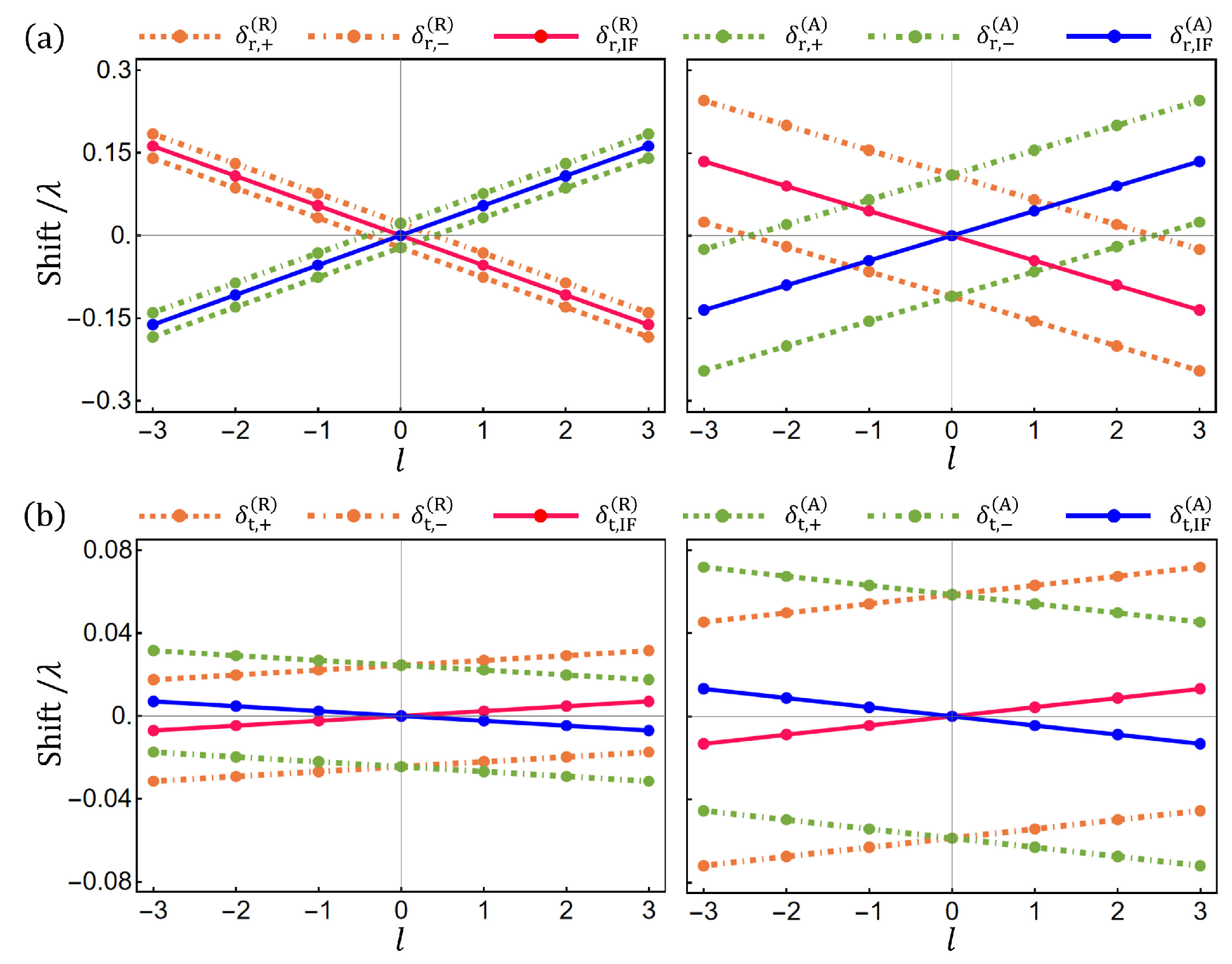
From Equations (8) and (10), we see that the IF shift is an average of the opposite SHE shifts of the two spin components, i.e., δ r ( t ) , I F ( R , A ) = 1 2 δ r ( t ) , + ( R , A ) + δ r ( t ) , ( R , A ) . Furthermore, we find δ r ( t ) , + ( R , A ) δ r ( t ) , I F ( R , A ) = δ r ( t ) , ( R , A ) δ r ( t ) , I F ( R , A ) . This means that the SHE shifts δ r ( t ) , ± ( R , A ) are symmetrical about the centroid of the reflected (refracted) beam, determined by the IF shift δ r ( t ) , I F ( R , A ) , though they are asymmetrical about the centroid of the incident beam, as shown in Figure 1. This can also be clearly seen in Figure 3, in which we plot δ r ( t ) , ± ( R , A ) and δ r ( t ) , I F ( R , A ) as a function of l with the incidence angle θ i = 30 and 60 . It is seen that both δ r ( t ) , ± ( R , A ) and δ r ( t ) , I F ( R , A ) depend linearly on l. As l changes from negative to positive values, δ r , ± ( R ) , δ r , I F ( R ) , δ t , ± ( A ) , and δ t , I F ( A ) decrease, while δ r , ± ( A ) , δ r , I F ( A ) , δ t , ± ( R ) , and δ t , I F ( R ) increase. When l = 0 , one has the symmetrical SHE shifts of δ r , ± ( R , A ) = ± ( r p 2 δ r , H + r s 2 δ r , V ) / ( r p 2 + r s 2 ) and δ t , ± ( R , A ) = ± ( t p 2 δ t , H + t s 2 δ t , V ) / ( t p 2 + t s 2 ) . In this case, the IF shifts δ r ( t ) , I F ( R , A ) = 0 .
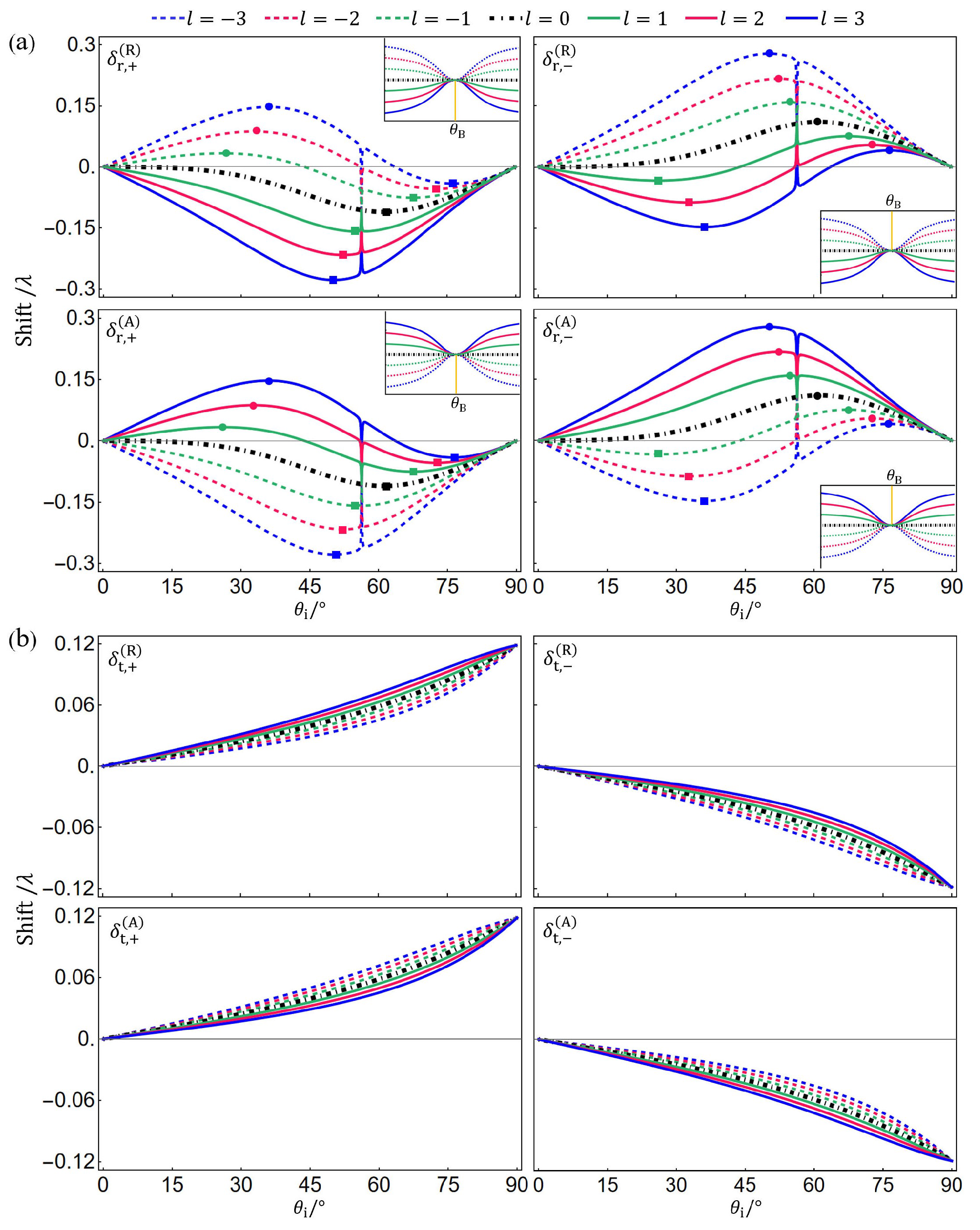
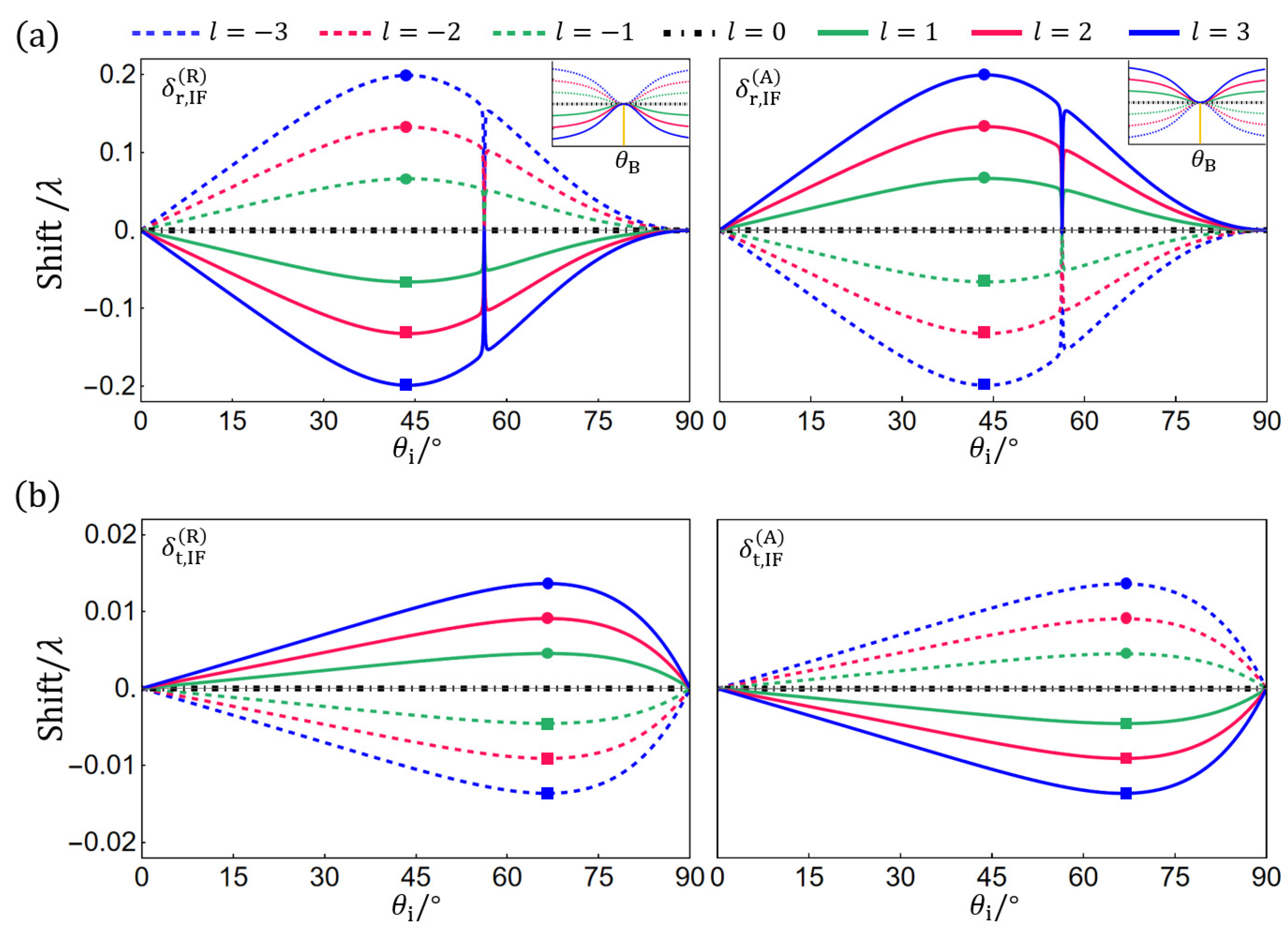
Figure 4 plots the SHE shifts δ r ( t ) , ± ( R , A ) versus the incidence angle θ i with different topological charges l. At the Brewster angle of θ B 56 . 6 , the reflection coefficient r p = 0 and the SHE shifts of the reflected beams δ r , ± ( R , A ) = ± δ r , V , which is independent of l. In the case of reflection, the SHE shifts δ r , ± ( R , A ) as a function of θ i exhibits different features for l < 0 and l > 0 . For example, when l < 0 (the dashed lines), as θ i goes from 0 to 90 , δ r , + ( R ) increases from zero to a positive maximum, then decreases to a negative minimum (except for the range near θ B ), and finally returns to zero. There exist two extreme points except for θ i = θ B . However, when l > 0 (the solid lines), δ r , + ( R ) decreases from 0 to a negative minimum and then returns to zero (except for the range near θ B ). There exists only one extreme point except for θ i = θ B . l = 0 is the critical case (the black dot-dashed line), in which the first extreme point is found at θ i = 0 . In the case of refraction, as θ i goes from 0 to 90 , the SHE shifts δ t , + ( R , A ) increase monotonically from 0 to a positive maximum, while δ t , ( R , A ) decrease monotonically from 0 to a negative minimum. There is no extreme point. For the IF shifts δ r ( t ) , IF ( R , A ) as a function of θ i , as shown in Figure 5, there is only one maximum or minimum point except for θ i = θ B in both the cases of l > 0 and l < 0 . The maximum (minimum) point is located at θ i 43 . 8 for reflection and at θ i 66 . 5 for refraction. At the Brewster angle of θ B 56 . 6 , the IF shifts of the reflected beams δ r , IF ( R , A ) = 0 .
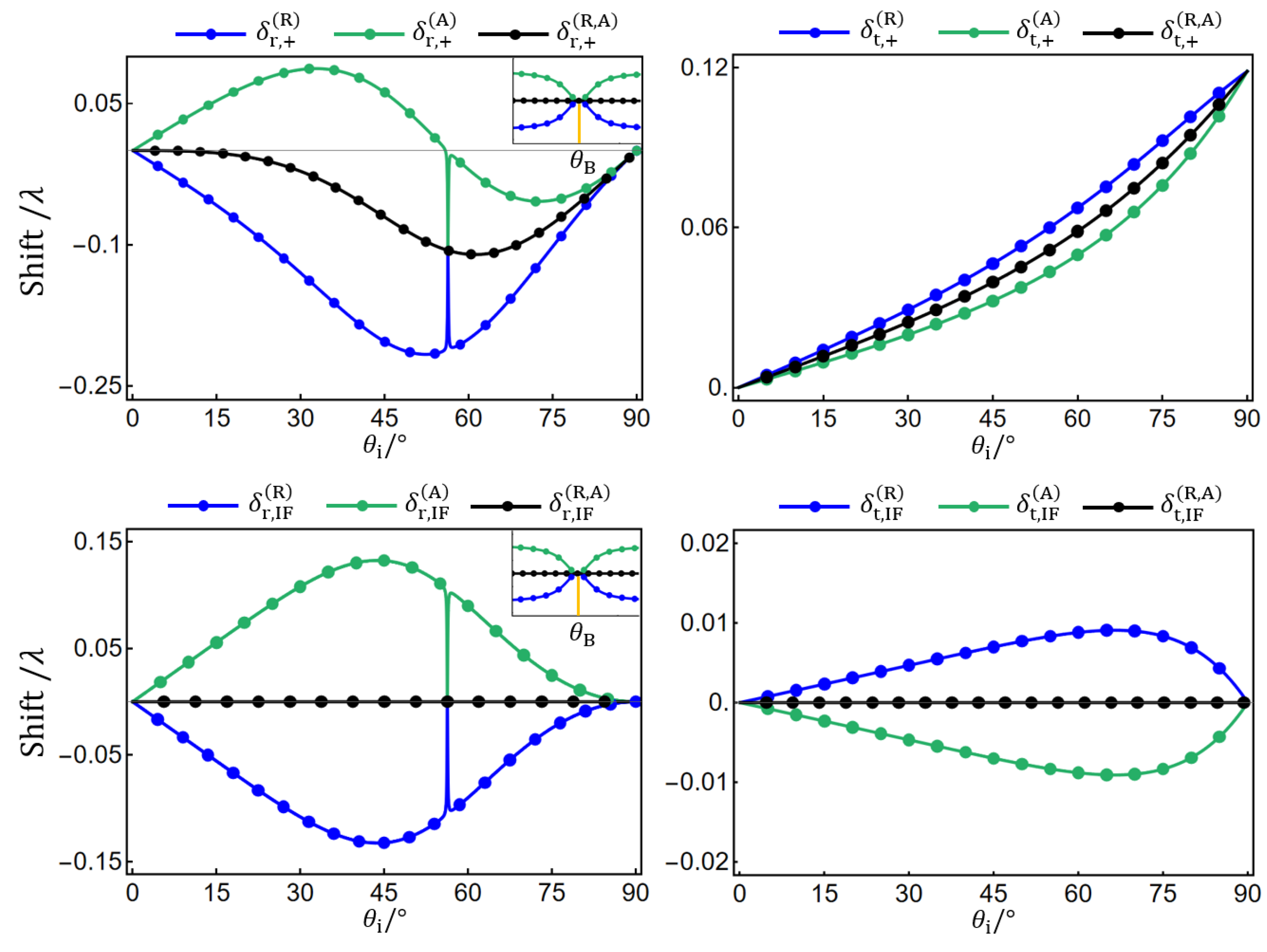
To verify the analytical results (Equations (8) and (10)), we perform numerical calculations using Equations (6) and (9). The numerical results are compared with analytical ones in Figure 6 for topological charge l = 0 , 2 , which shows good agreement even near the Brewster angle.

3. Weak Measurement of SHE Shifts

The SHE and related IF shifts are only a fraction of the wavelength (see Figure 3, Figure 4 and Figure 5), so it is difficult to observe them directly using, e.g., a camera or a quadrant detector. The weak-measurement technique can greatly enhance the tiny shifts by employing a pre- and post-selection scheme, allowing the experimental observation of the effects. In this section, we discuss how to properly choose the pre- and post-selection polarization states so as to amplify the SHE and IF shifts of the RVB and AVB. For clarity, we omit the subscripts i, r, and t of the basis vectors in the following equations.
The SHE shifts of the RVB and AVB can be rewritten in the unified form of
δ ± = ± δ 1 + δ IF ,
where δ 1 is the l-independent shift and δ IF is the l-dependent IF shift (see Equations (8) and (10)). We first choose the radial polarization as the pre-selection state: ϵ ^ pre = e ^ r = 1 2 e i ϕ e ^ + + e i ϕ e ^ . Upon reflection (refraction), the incident beam E i = u l ( y ) ϵ ^ pre evolves to
E r ( t ) = 1 2 e i ϕ u l ( y δ + ) e ^ + + 1 2 e i ϕ u l ( y δ ) e ^ u l ( y δ IF ) e ^ r i u l y δ 1 e ^ ϕ .
In the second step, we use u l ( y δ ± ) = u l ( y δ 1 δ IF ) u l ( y δ IF ) u l / y δ 1 and e ^ ϕ = i 2 e i ϕ e ^ + e i ϕ e ^ . The post-selection state is a superposition of the radial and azimuthal polarizations: ϵ ^ post = sin η e ^ r + i cos η e ^ ϕ . Projecting the reflected (refracted) beam E r t on the post-selection state ϵ ^ post yields
ϵ ^ post * · E r ( t ) = sin η u l ( y δ IF ) cos η u l y δ 1 .
When the post-selection state ϵ ^ post is nearly orthogonal to the pre-selection state ϵ ^ pre , i.e., ϵ ^ post * · ϵ ^ pre = sin η 1 and thus η 1 , one obtains ϵ ^ post * · E r ( t ) η u l ( y δ IF ) u l / y δ 1 η u l ( y δ IF η 1 δ 1 ) . The l-independent shift δ 1 is amplified by a factor of η 1 , which can be very large. The amplification factor is restricted by η 1 k w 0 = 2 π w 0 / λ [44,45]. For λ = 632.8 nm and w 0 = 50 λ , one has 1 η 1 314 . For a larger beam waist of w 0 = 200 λ , η can be as large as 1257.
However, the above scheme can only amplify the l-independent shift δ 1 . To amplify the l-dependent IF shift δ IF , a different pre- and post-selection scheme should be used. Here, we choose the right-handed circular polarization as the pre-selection state: ϵ ^ pre = e ^ + . It is a superposition of the radial and azimuthal polarizations: ϵ ^ pre = 1 2 e i ϕ e ^ r + i e ^ ϕ . After reflection (refraction) at the interface, the radial and azimuthal components of the incident beam E i = u l ( y ) ϵ ^ pre = 1 2 e i ϕ u l ( y ) e ^ r + i 2 e i ϕ u l ( y ) e ^ ϕ experience the opposite IF shifts δ IF R = l δ 2 and δ IF A = δ IF R = l δ 2 (see Equation (10)),
E r ( t ) = 1 2 e i ϕ u l y δ IF R e ^ r + i 2 e i ϕ u l y δ IF A e ^ ϕ u l y e ^ + e 2 i ϕ u l y l δ 2 e ^ .
In this scheme, the post-selection state is a superposition of the right- and left-handed circular polarizations: ϵ ^ post = sin η e i ϕ e ^ + + cos η e i ϕ e ^ . Projecting E r t on ϵ ^ post yields
ϵ ^ post * · E r ( t ) = e i ϕ sin η u l ( y ) e i ϕ cos η u l y l δ 2 .
When η 1 and thus ϵ ^ post * · ϵ ^ pre 1 , one has ϵ ^ post * · E r t e i ϕ η u l ( y ) e i ϕ u l / y l δ 2 e i ϕ η u l ( y η 1 l δ 2 ) . Therefore, the l-dependent IF shift l δ 2 is amplified by using this scheme.
The pre- and post-selections can be readily performed by a proper combination of a polarizer, a half-wave plate (HWP), a quarter-wave plate (QWP), and a vortex plate (VP), as illustrated in Figure 7. The HWP, QWP, and VP are described by the Jones matrices
T HWP = cos 2 α sin 2 α sin 2 α cos 2 α , T QWP = 1 0 0 i , T VP = cos ϕ sin ϕ sin ϕ cos ϕ ,
respectively. Here, α is the angle between the fast axis of the HWP and the x-axis. The fast axis of the QWP is fixed at an angle of 45 to the x-axis. In the scheme to amplify the l-independent shift δ 1 , the pre-selection state ϵ ^ pre = e ^ r can be prepared via a horizontal polarizer followed by a VP: T VP · x ^ = ϵ ^ pre . The post-selection state ϵ ^ post = sin η e ^ r + i cos η e ^ ϕ can be obtained via a combination of a horizontal polarizer, an HWP, a QWP, and a VP: T VP · T QWP · T HWP · x ^ = ϵ ^ post with α = π / 4 η / 2 . In the scheme to amplify the l-dependent IF shift δ IF , the pre-selection state ϵ ^ pre = e ^ + can be prepared via a horizontal polarizer followed by an HWP and a QWP: T QWP · T HWP · x ^ = ϵ ^ pre with α = 22 . 5 . The post-selection state ϵ ^ post = sin η e i ϕ e ^ + + cos η e i ϕ e ^ = cos η π / 4 e ^ r + i sin η π / 4 e ^ ϕ can be obtained via a combination of a horizontal polarizer, an HWP, a QWP, and a VP: T VP · T QWP · T HWP · x ^ = ϵ ^ post with α = η / 2 π / 8 . It should be noted that the sequence of the optical elements used to perform the post-selection projection is reversed from that used to prepare the post-selection state.

4. Discussion

Here, we would like to emphasize the difference between our research and previously reported relevant studies on the SHE of light. In most of the previous studies on the SHE of light at various interfaces [1,2], the incident beam is polarized homogeneously. The incidence polarization vector can be written as ϵ ^ i = α x ^ i + β y ^ with α and β being independent of the transverse coordinates x i and y. This means that the incidence polarization is spatially uniform. However, in our research, the incident CVVB has inhomogeneous polarization. The incidence polarization vectors of RVB and AVB are ϵ ^ i = cos ϕ i x ^ i + sin ϕ i y ^ and ϵ ^ i = sin ϕ i x ^ i + cos ϕ i y ^ , respectively, with ϕ i = arctan ( y / x i ) dependent on the transverse coordinates x i and y. The incidence polarization is spatially varying. Although the so-called intrinsic SHE of CVVB has been observed when the beam passes through a fan-shaped aperture [46,47], the study on the SHE of CVVB at interfaces has not been reported so far to the best of our knowledge.
The SHE shifts of RVB and AVB consist of an l-independent shift and an l-dependent IF shift (see Equation (11)). To amplify these two components of the SHE shifts, we propose a weak-measurement scheme with two different configurations of the pre- and post-selection polarizations. The l-independent shift and the l-dependent shift are amplified by the two configurations, respectively. In the traditional weak-measurement scheme [15,16], which is basically the same as our scheme with the first configuration and is commonly employed in the experimental study of the SHE of homogeneously polarized beams, it is the difference of the opposite shifts of the RCP and LCP components that is amplified. However, for the RVB and AVB, the RCP and LCP components experience the same l-dependent shift, which cannot be amplified by the traditional weak-measurement scheme. In addition to the weak measurement, it has been shown that the Goos–Hänchen shift can be amplified via multiple reflections or refractions, where the shift is accumulated [48]. Therefore, it might be possible to amplify the SHE and the related IF shifts using a similar idea.
It is worth noting that the RVB and AVB experience different SHE shifts (see Equation (8)). This implies that the SHE shifts depend on the spatial distribution of the incidence polarization. Therefore, it is reasonable to expect that the SHE of more complex vector vortex beams, such as the high-order CVVBs and high-order Poincaré sphere beams, would exhibit interesting features, which may find applications in the SHE-based precision measurement. In the previously reported SHE-based precision measurement scheme, the homogeneously polarized beam is employed to produce the SHE shift, which is amplified via the weak measurement and then is used to estimate the physical quantity to be measured [18,19,20,21]. Utilizing the vector vortex beams mentioned above in the SHE-based precision measurement could offer more degrees of freedom, e.g., topological charge, azimuthal order of polarization, and coordinates on the Poincaré sphere, to estimate the physical quantity to be measured, and thus might improve the accuracy of the measurement.
Due to the weak spin-orbit interaction of light induced by the plane dielectric interface, such as the air-glass interface, the SHE shifts are rather tiny. A possible way to enhance the SHE of light is to employ the system that can induce strong spin-orbit interaction of light. It has been shown that the rapidly varying phase discontinuities along a metasurface can introduce strong spin-orbit interaction, resulting in large SHE shifts [49]. Another possible way to induce strong spin-orbit interaction and thus to enhance the SHE of light is to replace dielectric interfaces with metallic surfaces because of the excitation of surface plasmon polaritons. Currently, the study on the quasi-bound states in the continuum (quasi-BIC) excited in all-dielectric metasurfaces has attracted enormous attention. Switching and tuning the quasi-BIC using phase change materials has been demonstrated [50]. It might be expected that employing the quasi-BIC may give rise to strong spin-orbit interaction and switchable and tunable SHE of light [9].

5. Conclusions

In conclusion, we have theoretically studied the SHE of CVVBs. Taking RVB and AVB as two examples of CVVBs, we have derived the analytical expressions of the SHE shifts and the related IF shifts of the reflected and refracted beams at a dielectric interface separating two isotropic media. We have shown that the SHE shifts of the two spin components are asymmetrical. This leads to the nonzero IF shifts, which are the average of the opposite SHE shifts. The SHE shifts are symmetrical about the centroid of the reflected (refracted) beam determined by the IF shift. Both the SHE and IF shifts increase or decrease linearly as the topological charge increases. The dependencies of the SHE shifts on the incidence angle exhibit different features for the positive and negative topological charges. For the air-glass (BK7) interface with the refractive indexes of n = 1 and n = 1.515 , the IF shifts reach the maximum or minimum at an incidence angle of θ i 43 . 8 and 66 . 5 in the cases of reflection and refraction, respectively. The predicted SHE and IF shifts are a fraction of the wavelength. Based on the weak measurement, we propose a pre- and post-selection scheme to amplify these tiny shifts, allowing the experimental investigation of the effects. The amplification coefficient can be as large as ∼10 3 with reasonable experimental parameters. Our research could be extended to study the SHE of other complex vector vortex beams, such as high-order CVVBs, high-order Poincaré sphere beams, etc. Utilizing these inhomogeneously polarized beams in the SHE-based precision measurement could offer more degrees of freedom to estimate the physical quantity to be measured, and might provide the possibility to improve the measurement accuracy.

Author Contributions

Conceptualization, J.W.; methodology, J.W.; software, X.Z. and S.W.; investigation X.Z.; writing—original draft preparation, X.Z.; writing—review and editing, J.W. and X.Z.; visualization, X.Z.; supervision, J.W. and J.L. (Jinhong Li); funding acquisition, J.W. and J.L. (Jinhong Liu). All authors have read and agreed to the published version of the manuscript.

Funding

This research was funded by the National Natural Science Foundation of China (Grant Nos. 12004334, 12104332), Taiyuan University of Science and Technology Scientific Research Initial Funding (Grant Nos. 20212076, 20222061), Taiyuan Institute of Technology Scientific Research Initial Funding (Grant Nos. 2022KJ071, 2022LJ018), China Postdoctoral Science Foundation (Grant No. 2020M671686).

Institutional Review Board Statement

Not applicable.

Informed Consent Statement

Not applicable.

Data Availability Statement

The data presented in this study are available on request from the corresponding author.

Conflicts of Interest

The authors declare no conflict of interest.

References

  1. Kim, M.; Yang, Y.; Lee, D.; Kim, Y.; Kim, H.; Rho, J. Spin Hall effect of light: From fundamentals to recent advancements. Laser Photonics Rev. 2023, 17, 2200046. [Google Scholar] [CrossRef]
  2. Ling, X.; Zhou, X.; Huang, K.; Liu, Y.; Qiu, C.W.; Luo, H.; Wen, S. Recent advances in the Spin Hall effect of light. Rep. Prog. Phys. 2017, 80, 066401. [Google Scholar] [CrossRef] [PubMed]
  3. Bliokh, K.Y.; Rodríguez-Fortuño, F.J.; Nori, F.; Zayats, A.V. Spin-orbit interactions of light. Nat. Photonics 2015, 9, 796–808. [Google Scholar] [CrossRef]
  4. Onoda, M.; Murakami, S.; Nagaosa, N. Hall effect of light. Phys. Rev. Lett. 2004, 93, 083901. [Google Scholar] [CrossRef] [PubMed]
  5. Bliokh, K.Y.; Bliokh, Y.P. Conservation of angular momentum, transverse shift, and Spin Hall effect in reflection and refraction of an electromagnetic wave packet. Phys. Rev. Lett. 2006, 96, 073903. [Google Scholar] [CrossRef]
  6. Bliokh, K.Y.; Bliokh, Y.P. Polarization, transverse shifts, and angular momentum conservation laws in partial reflection and refraction of an electromagnetic wave packet. Phys. Rev. E 2007, 75, 066609. [Google Scholar] [CrossRef] [PubMed]
  7. Bliokh, K.Y.; Niv, A.; Kleiner, V.; Hasman, E. Geometrodynamics of spinning light. Nat. Photonics 2008, 2, 748–753. [Google Scholar] [CrossRef]
  8. Bliokh, K.Y.; Samlan, C.T.; Prajapati, C.; Puentes, G.; Viswanathan, N.K.; Nori, F. Spin-Hall effect and circular birefringence of a uniaxial crystal plate. Optica 2016, 3, 1039–1047. [Google Scholar] [CrossRef]
  9. Wang, J.; Shi, L.; Zi, J. Spin Hall effect of light via momentum-space topological vortices around bound states in the continuum. Phys. Rev. Lett. 2022, 129, 236101. [Google Scholar] [CrossRef]
  10. Bardon-brun, T.; Delande, D.; Cherroret, N. Spin Hall effect of light in a random medium. Phys. Rev. Lett. 2019, 123, 043901. [Google Scholar] [CrossRef]
  11. Dai, H.; Yuan, L.; Yin, C.; Cao, Z.; Chen, X. Direct visualizing the Spin Hall effect of light via ultrahigh-order modes. Phys. Rev. Lett. 2020, 124, 053902. [Google Scholar] [CrossRef] [PubMed]
  12. Kim, M.; Lee, D.; Yang, Y.; Kim, Y.; Rho, J. Reaching the highest efficiency of Spin Hall effect of light in the near-infrared using all-dielectric metasurfaces. Nat. Commun. 2022, 13, 2036. [Google Scholar] [CrossRef] [PubMed]
  13. Peng, L.; Ren, H.; Liu, Y.C.; Lan, T.W.; Xu, K.W.; Ye, D.X.; Sun, H.B.; Xu, S.; Chen, H.S.; Zhang, S. Spin Hall effect of transversely spinning light. Sci. Adv. 2022, 8, eabo6033. [Google Scholar] [CrossRef] [PubMed]
  14. Oancea, M.A.; Joudioux, J.; Dodin, I.Y.; Ruiz, D.E.; Paganini, C.F.; Andersson, L. Gravitational Spin Hall effect of light. Phys. Rev. D 2020, 102, 024075. [Google Scholar] [CrossRef]
  15. Hosten, O.; Kwiat, P. Observation of the Spin Hall effect of light via weak measurements. Science 2008, 319, 787–790. [Google Scholar] [CrossRef]
  16. Qin, Y.; Li, Y.; He, H.; Gong, Q. Measurement of spin Hall effect of reflected light. Opt. Lett. 2009, 34, 2551–2553. [Google Scholar] [CrossRef]
  17. Ritchie, N.W.M.; Story, J.G.; Hulet, R.G. Realization of a measurement of a ‘weak value’. Phys. Rev. Lett. 1991, 66, 1107–1110. [Google Scholar] [CrossRef]
  18. Wang, B.; Rong, K.; Maguid, E.; Kleiner, V.; Hasman, E. Probing nanoscale fluctuation of ferromagnetic meta-atoms with a stochastic photonic Spin Hall effect. Nat. Nanotechnol. 2020, 15, 450–456. [Google Scholar] [CrossRef]
  19. Chen, S.; Ling, X.; Shu, W.; Luo, H.; Wen, S. Precision measurement of the optical conductivity of atomically thin crystals via the photonic spin Hall effect. Phys. Rev. Appl. 2020, 13, 014057. [Google Scholar] [CrossRef]
  20. Wang, R.; Zhou, J.; Zeng, K.; Chen, S.; Ling, X.; Shu, W.; Luo, H.; Wen, S. Ultrasensitive and real-time detection of chemical reaction rate based on the photonic Spin Hall effect. APL Photonics 2020, 5, 016105. [Google Scholar] [CrossRef]
  21. Zhou, X.; Ling, X.; Luo, H.; Wen, S. Identifying graphene layers via Spin Hall effect of light. Appl. Phys. Lett. 2012, 101, 251602. [Google Scholar] [CrossRef]
  22. Forbes, A.; de Oliveira, M.; Dennis, M.R. Structured light. Nat. Photonics 2021, 15, 253–262. [Google Scholar] [CrossRef]
  23. Forbes, A. Structured light from lasers. Laser Photonics Rev. 2019, 13, 1900140. [Google Scholar] [CrossRef]
  24. Zhan, Q. Cylindrical vector beams: From mathematical concepts to applications. Adv. Opt. Photonics 2009, 1, 1–57. [Google Scholar] [CrossRef]
  25. Holleczek, A.; Aiello, A.; Gabriel, C.; Marquardt, C.; Leuchs, G. Classical and quantum properties of cylindrically polarized states of light. Opt. Express 2011, 19, 9714–9736. [Google Scholar] [CrossRef] [PubMed]
  26. Wang, X.L.; Ding, J.; Ni, W.J.; Guo, C.S.; Wang, H.T. Generation of arbitrary vector beams with a spatial light modulator and a common path interferometric arrangement. Opt. Lett. 2007, 32, 3549–3551. [Google Scholar] [CrossRef]
  27. Bomzon, Z.; Biener, G.; Kleiner, V.; Hasman, E. Radially and azimuthally polarized beams generated by space-variant dielectric subwavelength gratings. Opt. Lett. 2002, 27, 285–287. [Google Scholar] [CrossRef]
  28. Rumala, Y.S.; Milione, G.; Nguyen, T.A.; Pratavieira, S.; Hossain, Z.; Nolan, D.; Slussarenko, S.; Karimi, E.; Marrucci, L.; Alfano, R.R. Tunable supercontinuum light vector vortex beam generator using a q-plate. Opt. Lett. 2013, 38, 5083–5086. [Google Scholar] [CrossRef]
  29. Cardano, F.; Karimi, E.; Slussarenko, S.; Marrucci, L.; de Lisio, C.; Santamato, E. Polarization pattern of vector vortex beams generated by q-plates with different topological charges. Appl. Opt. 2012, 51, C1–C6. [Google Scholar] [CrossRef]
  30. Marrucci, L.; Manzo, C.; Paparo, D. Optical spin-to-orbital angular momentum conversion in inhomogeneous anisotropic media. Phys. Rev. Lett. 2006, 96, 163905. [Google Scholar] [CrossRef]
  31. Yue, F.; Wen, D.; Xin, J.; Gerardot, B.D.; Li, J.; Chen, X. Vector vortex beam generation with a single plasmonic metasurface. ACS Photonics 2016, 3, 1558–1563. [Google Scholar] [CrossRef]
  32. Yi, X.; Ling, X.; Zhang, Z.; Li, Y.; Zhou, X.; Liu, Y.; Chen, S.; Luo, H.; Wen, S. Generation of cylindrical vector vortex beams by two cascaded metasurfaces. Opt. Express 2014, 22, 17207–17215. [Google Scholar] [CrossRef] [PubMed]
  33. Shen, Y.; Wang, X.; Xie, Z.; Min, C.; Fu, X.; Liu, Q.; Gong, M.; Yuan, X. Optical vortices 30 years on: OAM manipulation from topological charge to multiple singularities. Light Sci. Appl. 2019, 8, 90. [Google Scholar] [CrossRef] [PubMed]
  34. Bozinovic, N.; Yue, Y.; Ren, Y.; Tur, M.; Kristensen, P.; Huang, H.; Willner, A.E.; Ramachandran, S. Terabit-scale orbital angular momentum mode division multiplexing in fibers. Science 2013, 340, 1545–1548. [Google Scholar] [CrossRef]
  35. Wang, J.; Yang, J.Y.; Fazal, I.M.; Ahmed, N.; Yan, Y.; Huang, H.; Ren, Y.; Yue, Y.; Dolinar, S.; Tur, M.; et al. Terabit free-space data transmission employing orbital angular momentum multiplexing. Nat. Photonics 2012, 6, 488–496. [Google Scholar] [CrossRef]
  36. Willner, A.E.; Pang, K.; Song, H.; Zou, K.; Zhou, H. Orbital angular momentum of light for communications. Appl. Phys. Rev. 2021, 8, 041312. [Google Scholar] [CrossRef]
  37. Yoshida, M.; Kozawa, Y.; Sato, S. Subtraction imaging by the combination of higher-order vector beams for enhanced spatial resolution. Opt. Lett. 2019, 44, 883–886. [Google Scholar] [CrossRef]
  38. Kozawa, Y.; Matsunaga, D.; Sato, S. Superresolution imaging via superoscillation focusing of a radially polarized beam. Optica 2018, 5, 86–92. [Google Scholar] [CrossRef]
  39. Kritzinger, A.; Forbes, A.; Forbes, P.B. Optical trapping and fluorescence control with vectorial structured light. Sci. Rep. 2022, 12, 17690. [Google Scholar] [CrossRef]
  40. Castellucci, F.; Clark, T.W.; Selyem, A.; Wang, J.; Franke-Arnold, S. Atomic compass: Detecting 3D magnetic field alignment with vector vortex light. Phys. Rev. Lett. 2021, 127, 233202. [Google Scholar] [CrossRef]
  41. Bliokh, K.Y.; Aiello, A. Goos–Hänchen and Imbert-Fedorov beam shifts: An overview. J. Opt. 2013, 15, 014001. [Google Scholar] [CrossRef]
  42. Kong, L.J.; Wang, X.L.; Li, S.M.; Li, Y.; Chen, J.; Gu, B.; Wang, H.T. Spin Hall effect of reflected light from an air-glass interface around the Brewster’s angle. Appl. Phys. Lett. 2012, 100, 071109. [Google Scholar] [CrossRef]
  43. Ling, X.; Xiao, W.; Chen, S.; Zhou, X.; Luo, H.; Zhou, L. Revisiting the anomalous Spin-Hall effect of light near the Brewster angle. Phys. Rev. A 2021, 103, 033515. [Google Scholar] [CrossRef]
  44. Dressel, J.; Malik, M.; Miatto, F.M.; Jordan, A.N.; Boyd, R.W. Colloquium: Understanding quantum weak values: Basics and applications. Rev. Mod. Phys. 2014, 86, 307–316. [Google Scholar] [CrossRef]
  45. Kofman, A.G.; Ashhab, S.; Nori, F. Nonperturbative theory of weak pre- and post-selected measurements. Phys. Rep. 2012, 520, 43–133. [Google Scholar] [CrossRef]
  46. Ling, X.; Yi, X.; Zhou, X.; Liu, Y.; Shu, W.; Luo, H.; Wen, S. Realization of tunable spin-dependent splitting in intrinsic photonic Spin Hall effect. Appl. Phys. Lett. 2014, 105, 151101. [Google Scholar] [CrossRef]
  47. Zhang, Y.; Li, P.; Liu, S.; Zhao, J. Unveiling the photonic Spin Hall effect of freely propagating fan-shaped cylindrical vector vortex beams. Opt. Lett. 2015, 40, 4444–4447. [Google Scholar] [CrossRef] [PubMed]
  48. Goos, F.; Hänchen, H. Ein neuer und fundamentaler versuch zur totalreflexion. Ann. Phys. 1947, 436, 333–346. [Google Scholar] [CrossRef]
  49. Yin, X.; Ye, Z.; Rho, J.; Wang, Y.; Zhang, X. Photonic Spin Hall effect at metasurfaces. Science 2013, 339, 1405–1407. [Google Scholar] [CrossRef]
  50. Barreda, A.; Zou, C.; Sinelnik, A.; Menshikov, E.; Sinev, I.; Pertsch, T.; Staude, I. Tuning and switching effects of quasi-BIC states combining phase change materials with all-dielectric metasurfaces. Opt. Mater. Express 2022, 12, 3132–3142. [Google Scholar] [CrossRef]
Figure 1. Schematic diagram of the SHE of light at a dielectric interface between two media with the refractive indexes of n and n . δ r ( t ) , ± and δ r ( t ) , IF denote the SHE and related IF shifts of the reflected (refracted) beam, respectively. θ i , θ r , and θ t denote the angles of incidence, reflection, and refraction, respectively, and N denotes the normal to the interface. ( x i , y , z i ) , ( x r , y , z r ) , and ( x t , y , z t ) are the coordinate systems with z i -, z r -, and z t -axes attached to the incidence, reflection, and refraction directions, respectively, which are determined by the Snell’s law.
Photonics 10 01356 g001
Figure 2. (a) The RVB is a superposition of a horizontally polarized HG 10 mode and a vertically polarized HG 01 mode. (b) The AVB is a superposition of a horizontally polarized HG 01 mode and a vertically polarized HG 10 mode. The arrows represent the local polarization.
Photonics 10 01356 g002
Figure 3. The SHE shifts δ r ( t ) , ± R , A and the IF shifts δ r ( t ) , I F R , A of (a) the reflected beams and (b) the refracted beams versus the topological charge l with the incidence angle θ i = 30 (left column) and θ i = 60 (right column). The refractive indexes are taken as n = 1 and n = 1.515 . The beam waist is taken as w 0 = 50 λ .
Photonics 10 01356 g003
Figure 4. The SHE shifts δ r ( t ) , ± ( R , A ) of (a) the reflected beams and (b) the refracted beams versus the incidence angle θ i with the topological charge l [ 3 , 3 ] . The circle and the square symbols in (a) indicate the maximum and minimum points, respectively. The other parameters are as in Figure 3.
Photonics 10 01356 g004
Figure 5. The IF shifts δ r ( t ) , IF ( R , A ) of (a) the reflected beams and (b) the refracted beams versus the incidence angle θ i with the topological charge l [ 3 , 3 ] . The circle and the square symbols indicate the maximum and minimum points, respectively. The other parameters are as in Figure 3.
Photonics 10 01356 g005
Figure 6. Analytical results (lines) and numerical results (symbols) for the SHE shifts δ r ( t ) , ± ( R , A ) and IF shifts δ r ( t ) , I F ( R , A ) versus the incidence angle θ i with l = 2 (blue and green) and l = 0 (black). The other parameters are as in Figure 3.
Photonics 10 01356 g006
Figure 7. Pre- and post-selection schemes used to amplify (a) the l-independent shift δ 1 and (b) the l-dependent IF shift δ IF . P, polarizer; HWP, half-wave plate; QWP, quarter-wave plate; VP, vortex plate. The blue lines denote the orientation of the polarizer and the fast axes of the HWP and QWP.
Photonics 10 01356 g007
Disclaimer/Publisher’s Note: The statements, opinions and data contained in all publications are solely those of the individual author(s) and contributor(s) and not of MDPI and/or the editor(s). MDPI and/or the editor(s) disclaim responsibility for any injury to people or property resulting from any ideas, methods, instructions or products referred to in the content.