Article

Enhanced Measurement of Vortex Beam Rotation Using Polarization-Assisted Particle Swarm Optimization for Phase Retrieval

1
School of Physics, Harbin Institute of Technology, Harbin 150001, China
2
Shanghai Academy of Spaceflight Technology, Shanghai 200240, China
3
Infrared Detection Technology Research & Development Center of CASC, Shanghai 200240, China
*
Author to whom correspondence should be addressed.
Photonics 2023, 10(12), 1293; https://doi.org/10.3390/photonics10121293
Submission received: 28 October 2023 / Revised: 17 November 2023 / Accepted: 22 November 2023 / Published: 23 November 2023
(This article belongs to the Special Issue Nonlinear Optics and Hyperspectral Polarization Imaging)

Abstract

:
In detecting the rotation velocity of an object employing the rotational Doppler effect of vortex beams, atmospheric turbulence can easily cause phase distortion and spiral spectrum dispersion, consequently reducing velocity measurement accuracy. This study combines adaptive optical intelligence algorithms with polarization compensation information to propose a novel approach, the Stokes–Particle swarm optimization Gerchberg–Saxton (Stokes-PSO GS) algorithm, which integrates Stokes polarization information assistance and PSO for GS phase retrieval. The algorithm adjusts the phase and amplitude of the pre-compensated phase screen of the GS algorithm utilizing Stokes information of polarized vortex beam (with lL = 5 and lR = −5) before and after distortion. The PSO is then employed to optimize the pre-compensated phase screen and perform compensations. Simulation results at zS-T = 200 m and C n 2 = 1 × 10⁻¹⁴ m−2/3, demonstrate that the Stokes-PSO GS algorithm exhibits strong stability (small angular spectrum purity deviation, σp, Stokes-PSO GS = 0.005675% < σp, GS = 11.62%), superior optical field recovery (well-recovered Stokes optical field, up to 33.76% improvement in angular spectrum purity), and high-velocity measurement accuracy (25.93% improvement) compared to the GS algorithm. This approach enables precise measurement of the rotation velocity of the vortex beam, demonstrating its potential in practical applications.

1. Introduction

The vortex beam, a type of beam characterized by a spiral wavefront structure with Orbital angular momentum (OAM), carrying the phase factor of exp(i) [1], has a wide range of application potential [2]. When a beam illuminates a rotating object’s surface, it exhibits a frequency shift related to the object’s rotational velocity, known as the Rotational Doppler effect (RDE) of vortex beams [3]. The RDE offers advantages such as non-contact measurement, short response time, and high precision in rotation velocity measurement, making it widely studied [4,5,6] and highly regarded. Recently, researchers have made significant progress in the field of RDE. Studies on the speckle rotational Doppler frequency shift and the analysis of the OAM spectrum components [7] in complex optical fields have clarified the essence of this phenomenon. Research on the RDE in different application scenarios, such as oblique [8], off-axis incidence [9], and complex motion [10] has been carried out successively. The rotational velocity measurement is optimized by methods such as cascaded doubling [11] and balanced detection [12]. Additionally, Guo et al. further analyse the angular acceleration detection error of targets in non-line-of-sight scenarios [13,14]. Guo et al. achieve angular velocity measurement in the infrared region by combining the Second harmonic generation (SHG) and RDE [15]. These studies, while further clarifying the mechanism of the RDE, have also demonstrated the great potential of the RDE applications.
However, vortex beams are easily affected by random atmospheric turbulence in practical remote detection of the target rotation velocity, leading to beam distortion and OAM spectrum dispersion [16], thereby reducing the rotational velocity measurement accuracy. Early attempts utilized Adaptive optics (AO) compensation based on Shack–Hartmann (SH) wavefront sensors [17] to detect wavefront distortion of Gaussian probe beam. However, this method faced challenges in detecting the spiral wavefront structure of vortex beams. To address this issue, non-wavefront sensor methods combined with phase retrieval algorithms such as the Wirtinger flow (WF) [18] and Gerchberg–Saxton (GS) [19] play a crucial role in reducing beam distortions caused by atmospheric turbulence, which were previously commonly used in Coherent diffractive imaging (CDI) [20]. Within this scope, the GS algorithm, which calculates compensated phases based on distorted beam wavefronts in previous studies [21,22], has the ability to improve the velocity measurement accuracy to a certain extent.
Nonetheless, conventional adaptive optics compensation algorithms primarily rely on distorted optical fields’ phase and intensity information and often fall into local optima during the calculation process [23]. They suffer from limited compensation information acquisition dimensions, poor stability and optical field recovery quality [23,24]. Consequently, many researchers introduced intelligent algorithms such as the Artificial fish school algorithm (AFSA) [25], Convolutional neural networks (CNN) [26], and others [27,28,29] to further recover the optical field. In our work, this problem is addressed by proposing a research method that combines the GS algorithm with the Stokes polarization information assistance and Particle swarm optimization (PSO) algorithm, namely the Stokes-PSO GS algorithm, to compensate for the distorted vortex beam and improve velocity measurement accuracy. In previous studies, the Stokes polarisation information is widely used in polarisation imaging [30], but its potential for distorted optical field recovery and velocity measurement accuracy enhancement has been overlooked.
Specifically, the Stokes-PSO GS algorithm proposed in this work introduces the individual Stokes polarization components of the polarized vortex beams to obtain more compensation information and adjust the phase and amplitude of the pre-compensated phase screen. Afterwards, the PSO algorithm is further iteratively optimized to compensate for the distorted optical field more effectively, and finally, the best pre-compensated phase screen and the highest velocity measurement accuracy are obtained. Simulation results demonstrate that the Stokes-PSO GS algorithm effectively enhances the quality of optical field recovery compared to the GS algorithm, improves angular spectrum purity, and enhances rotational velocity measurement accuracy. It exhibits high algorithm stability, excellent optical field recovery, and high-velocity measurement accuracy. This work demonstrates the potential of introducing multi-dimensional compensation information to participate in the AO intelligent algorithm for distorted optical field compensation, which provides important support for improving the rotational velocity measurement accuracy of vortex beams on remote targets.

2. System Design

The system design’s schematic is illustrated in Figure 1. Generating a polarized vortex beam employed the grating diffraction method [31]. Two Spatial light modulators (SLM) with topological charges of −5 and 5, modulating in mutually perpendicular directions, were utilized to produce left- and right-circularly polarized vortex beams, respectively. The target beam was obtained by superimposing these beams. The polarized vortex beams with opposite topological charges, having similar phase structures, could perform phase compensation better. Figure 1 displays the phase grating patterns loaded on the SLM1 and SLM2 for Laguerre–Gaussian (LG) vortex beams [32] and the resulting beam patterns. The beam undergoes distortion through SLM3 loading a simulated random atmospheric turbulence phase screen. A randomly generated phase screen, obtained through the power spectrum inversion method, substituted the atmospheric turbulence process. The power spectrum employed a modified Von Karman spectrum [33], and the missing low-frequency components in the phase screen were compensated utilizing the sub-harmonic compensation method [34].
The beam passes through a Stokes detection system comprising a quarter-wave plate and linear polarizer. It simultaneously functions as a left/right circular polarized component selection system. It acquires the Stokes parameters of the undistorted and distorted beams, where S0 = I0, S1 = IHIV, S2 = IDIA, S3 = IRIL, and I0, IH, IV, ID, IA, IR, IL, represent the total intensity, horizontal, vertical, diagonal, anti-diagonal, right-circular, and left-circular polarized light intensities, respectively. After the beam illuminates the rotating target and reflects the return signal, the left/right circularly polarized component is selected. The selected left/right circularly polarized components are reflected by a beam splitter and focused by a lens onto a CCD detector, where the spot intensity is detected and recorded. The intensity information of the distorted left/right circularly polarized components and the Stokes intensity and phase information of the polarized vortex beam before and after turbulence distortion are utilized as initial conditions for the Stokes-PSO GS algorithm. This algorithm adjusts the phase and amplitude of the pre-compensated phase screen of the GS algorithm by utilizing the Stokes parameters to obtain more compensation information. Further optimization by the PSO algorithm gives the best compensation feedback on the screen. The use of polarisation Stokes to obtain multi-channel information and increase the dimensions of compensation information can obtain a better compensation matrix and velocimetry accuracy enhancement. The compensation phase screen obtained by the Stokes-PSO GS algorithm is loaded onto the SLM4. Another beam passes through SLM4 for phase recovery compensation. The intensity of the distorted beam and the recovered beam after compensation are presented in Figure 1. After interfering with the reference light, the echo photon signals are received and collected by an Avalanche photodiode (APD) detector, obtaining the temporal signal of the intensity. After the Fourier transform, the rotational Doppler frequency shift is extracted, which is used to calculate the target’s rotational velocity.

3. Stokes-PSO GS Algorithm

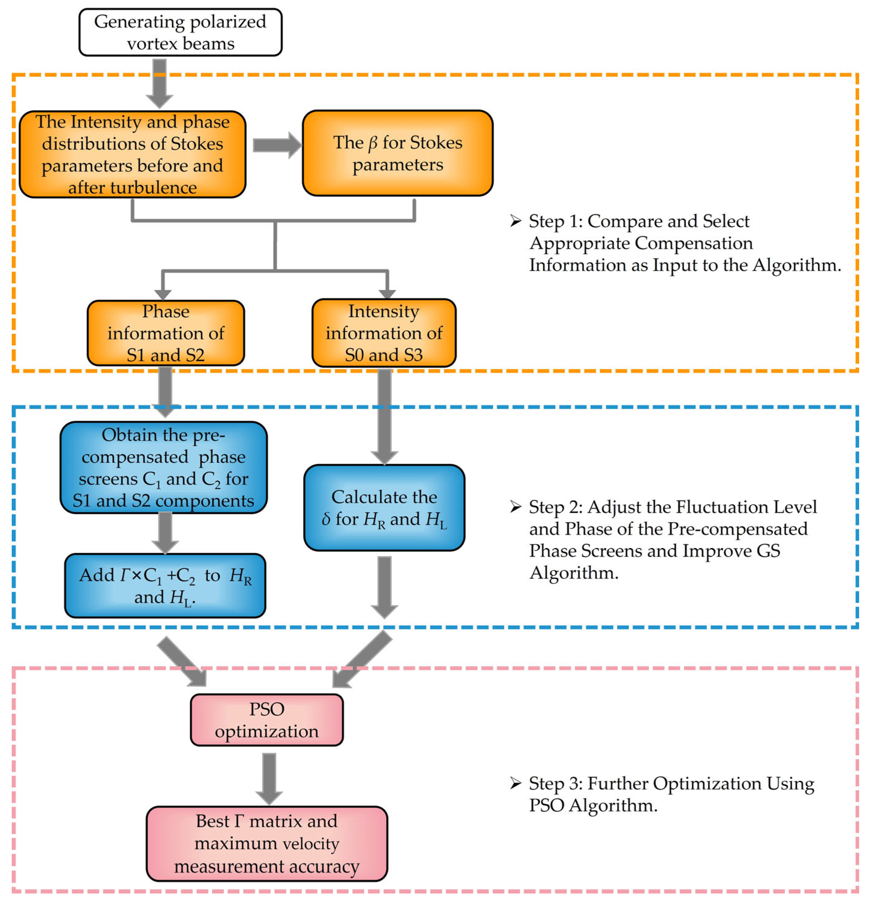
The workflow of the Stokes-PSO GS algorithm is depicted in Figure 2, involving the following three steps:
Step 1: Compare and Select Appropriate Compensation Information as Input to the Algorithm
Perform Stokes parameter detection on normal and distorted polarized vortex beams before and after passing through turbulence. Because S0 and S3 have S0 = IR + IL, S3 = IRIL relationship with IR, IL, the compensation obtained by utilizing S0, S3 light intensity information can be effectively transferred to IR, IL. As illustrated in Figure 3a,d, the neighbouring phase regions of S1 and S2 all have a phase difference of π. After turbulence, the phase becomes distorted, providing richer phase information. Therefore, the phase information of S1 and S2, along with the intensity information of S0 and S3, are selected as the input information for the algorithm. An auxiliary evaluation factor β is defined and calculated to further evaluate the Stokes intensity information. Here, SNR0 represents the signal-to-noise ratio of the spectrum during rotational velocimetry in non-turbulence, and σ I 2 d denotes the scintillation index within the effective receiving area of the beam. P0 and P represent the received optical power in non-turbulence and turbulence, respectively. Factor β comprehensively measures the ability of the Stokes parameters to resist the fluctuations caused by atmospheric turbulence and the velocity measurement accuracy of the vortex beam. Consequently, the amplitude adjustment factor δ for the pre-compensated phase screens can be calculated.
Step 2: Adjust the Fluctuation Level and Phase of the Pre-compensated Phase Screens and Improve the GS Algorithm.
Utilizing the intensity information from the S0 and S3 components and phase information from the S1 and S2 components as auxiliary data enhanced the GS algorithm here. Specifically, the pre-compensated phase screens for S1 and S2 components were computed utilizing the GS algorithm, incorporating a non-wavefront sensor compensation technique:
C 1 = a n g l e ( S 1 ) ϕ GS ,   S 1 C 2 = a n g l e ( S 2 ) ϕ GS ,   S 2
In these equations, angle(S1) and angle(S2) represent S1 and S2 phases under non-turbulence, ϕGS,S1 and ϕGS,S2 represent the phases of S1 and S2 obtained from the GS algorithm output. Γ × C1 + C2 is added to the original pre-compensated phase screens HR and HL of the original left and right circular polarized components, thus realizing the improvement of the GS algorithm employing the phase auxiliary information of the Stokes parameter. Here, Γ is an optimization coefficient matrix achieved through the PSO algorithm to minimize the velocity measurement error. The rotational Doppler velocimetry error of a vortex beam is given by σ Ω = 6 / l τ S N R , as derivate in Appendix A.
Subsequently, based on the relationship between S0, S3, IR and IL, analogous relationships can be established for δR + δL = βS0 and δRδL = βS3. Here, βS0 and βS3 represent auxiliary evaluation factors for S0 and S3, respectively, where βS0 = 0.9480 and βS3 = 0.1576. δL and δR evaluate the turbulence resistance ability of the left and right circularly polarized components. Thus, adjustment factors for the fluctuation levels of pre-compensated phase screens HL and HR obtained through the GS algorithm can be calculated: δR = 0.5528 and δL = 0.3952. The right-circular polarized component exhibits higher turbulence resistance ability. To enhance the turbulence resistance ability of the left-circular component, adjustments can be made to the pre-compensated phase screen of both left and right circularly polarized components utilizing the phase and intensity compensation information from the Stokes parameters:
H R = H R + δ L ( Γ C 1 + C 2 ) H L = H L + δ R ( Γ C 1 + C 2 )
Step 3: Further Optimization with the PSO Algorithm
The PSO is an intelligent parallel evolutionary algorithm that starts from random particles (random solutions). It evaluates the quality of solutions employing a fitness function, tracks individual and current global best values, iteratively updates their velocities and positions, and searches for the global optimum. The PSO possesses advantages such as ease of implementation, high precision, and fast convergence. In this step, the PSO is utilized to optimize the relative coefficient matrix by taking the highest or average velocity measurement accuracy of the left and right circular polarized components as the fitness function. The iterative updates enable the velocity measurement accuracy of the beam to reach its peak, ultimately obtaining the optimal velocity measurement accuracy and the corresponding Γ matrix.

4. Results and Analysis

4.1. Optical Field Recovery

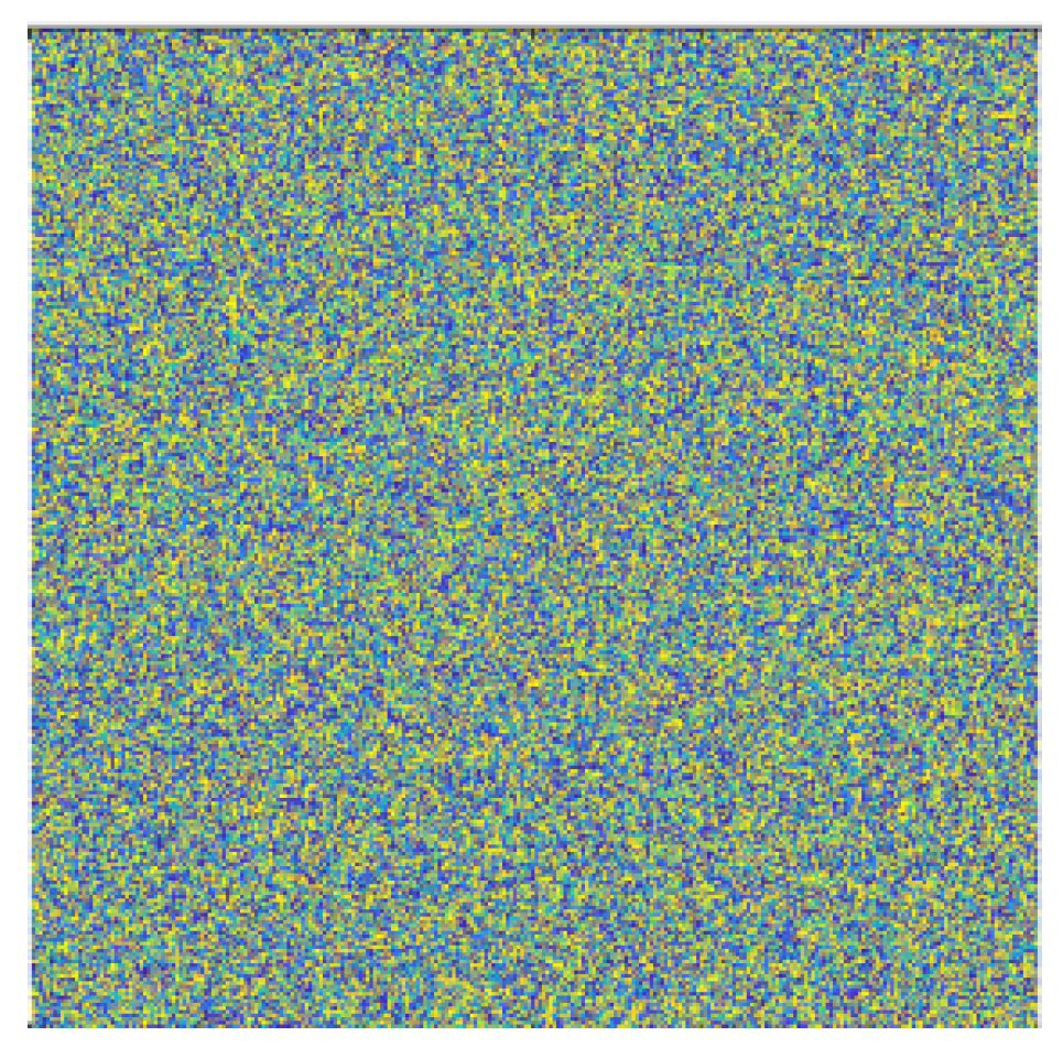
In this section, the distorted optical field of the polarized vortex beam with lL = 5 and lR = −5 is recovered utilizing the Stokes-PSO GS algorithm. The simulation parameters employed here are: λ = 532 nm, waist radius w0 = 0.003 m, SLM3 loaded with atmospheric turbulence intensity C n 2 = 1 × 10⁻¹⁴ m−2/3 phase screen, resolution 600 × 600, turbulent extra scale L = 20 m, turbulent inner scale l0 = 0.005 m, GS algorithm iterations NGS = 50, Ω = 50 rad/s, distance between the measurement system and the target zS-T = 200 m (both incident and return paths distance are 200 m), subharmonic number P = 3. Considering the large matrix size, achieving a balance between global search and self-optimization capabilities and between the breadth of solution space and computational time, the key parameters of the PSO algorithm, including the number of iterations NPSO, the number of particles NP, inertia weight α, self-cognitive factor m1, and social cognitive factor m2 are adjusted as follows: NPSO = 700, NP = 70, α= 0.8, m1 = m2 = 1.5. The system accuracy criterion is the lowest velocity measurement error of left and right circular polarized components. After 700 iterations, the relative coefficient matrix Γ corresponding to the lowest velocity measurement error obtained is presented in Figure 4.
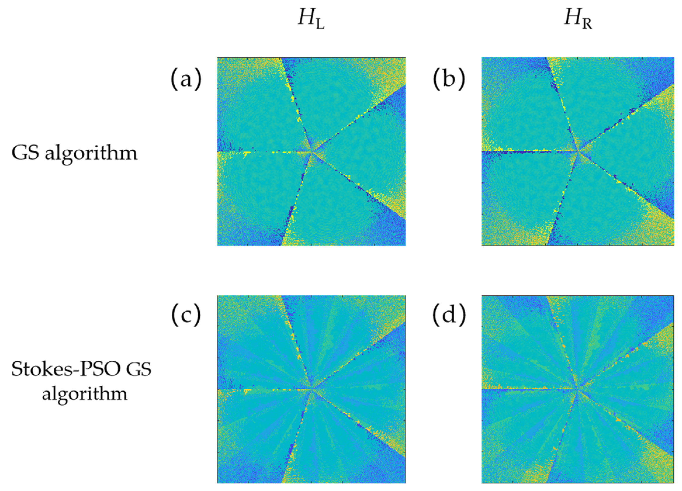
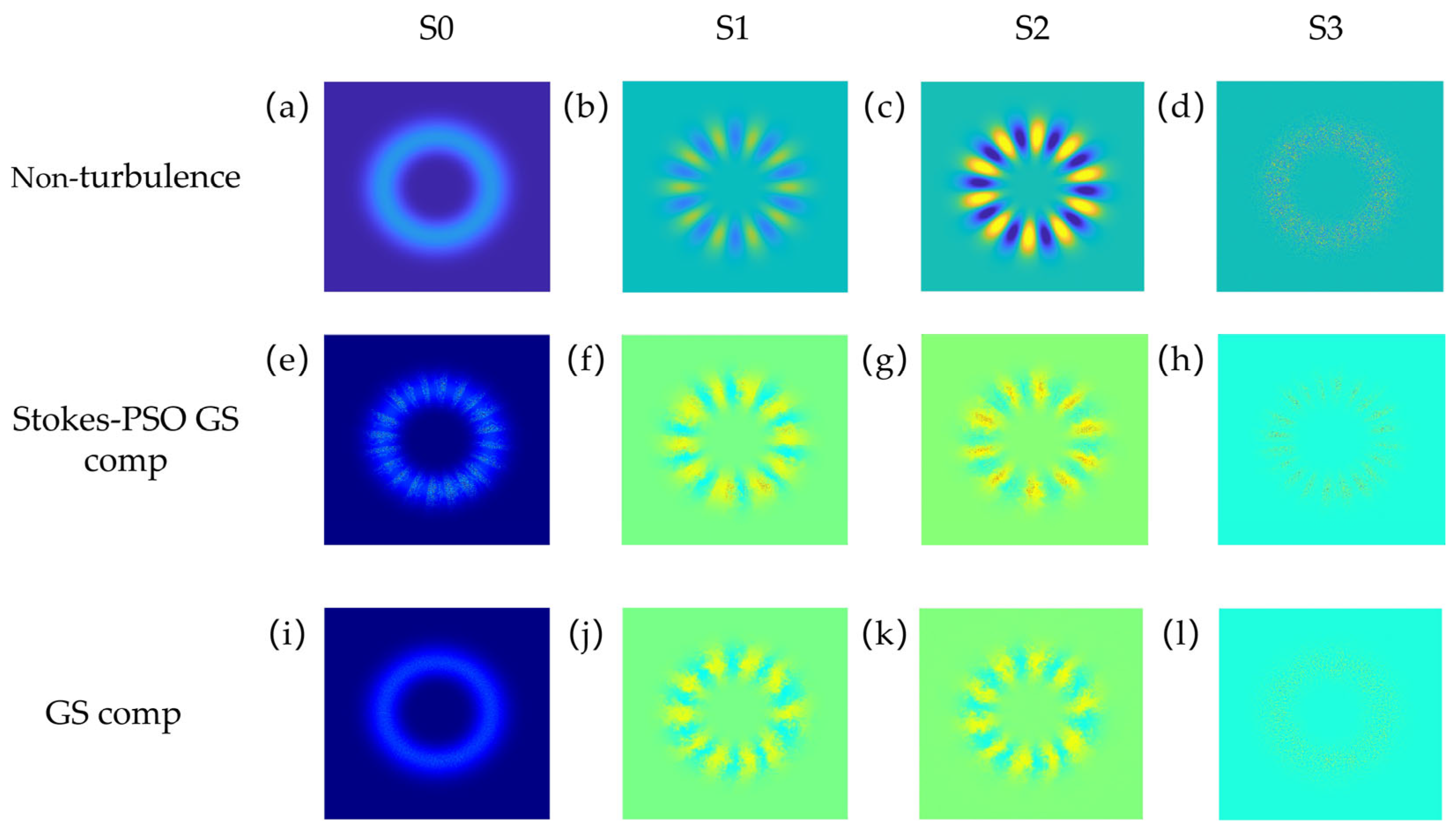
Figure 5 compares the pre-compensated phase screens obtained by the conventional GS algorithm and the Stokes-PSO GS algorithm. Based on the original vortex background phase structure with l cycles, the latter added a phase structure with equal phase interval modulation of S1 and S2 parameters, dividing the output phase obtained by the GS algorithm. More compensatory information was obtained by introducing the Stokes polarization information, increasing velocity measurement accuracy. In Figure 6e–h, the beam’s Stokes parameters in non-turbulence, after compensation employing the GS algorithm and the Stokes-PSO GS algorithm, are compared and analysed. It could be observed that the improvement brought by the Stokes-PSO GS algorithm mainly focused on the enhancement of the uniformly petal-shaped intensity distribution for S0, S2, and S3 components and a part region of S1. This enhancement was attributed to the introduction of Stokes information. Compared to the phase diagrams of S1 and S2 obtained in non-turbulence, compensated by the GS algorithm, the Stokes-PSO GS algorithm, illustrated in Figure 3b,e, demonstrates improved phase recovery owing to the introduced phase auxiliary information. It better reconstructs the phases around phase singularities (the region enclosed by red circles in Figure 3) and outer phase areas, reducing the ambiguity range. In addition, the Stokes-PSO GS algorithm achieves a better recovery of uniformly phase interval distribution than the GS algorithm. This similarity is particularly noticeable in the S1 and S2 components in non-turbulence.

4.2. Enhancement of Orbital Angular Momentum Spectrum Purity

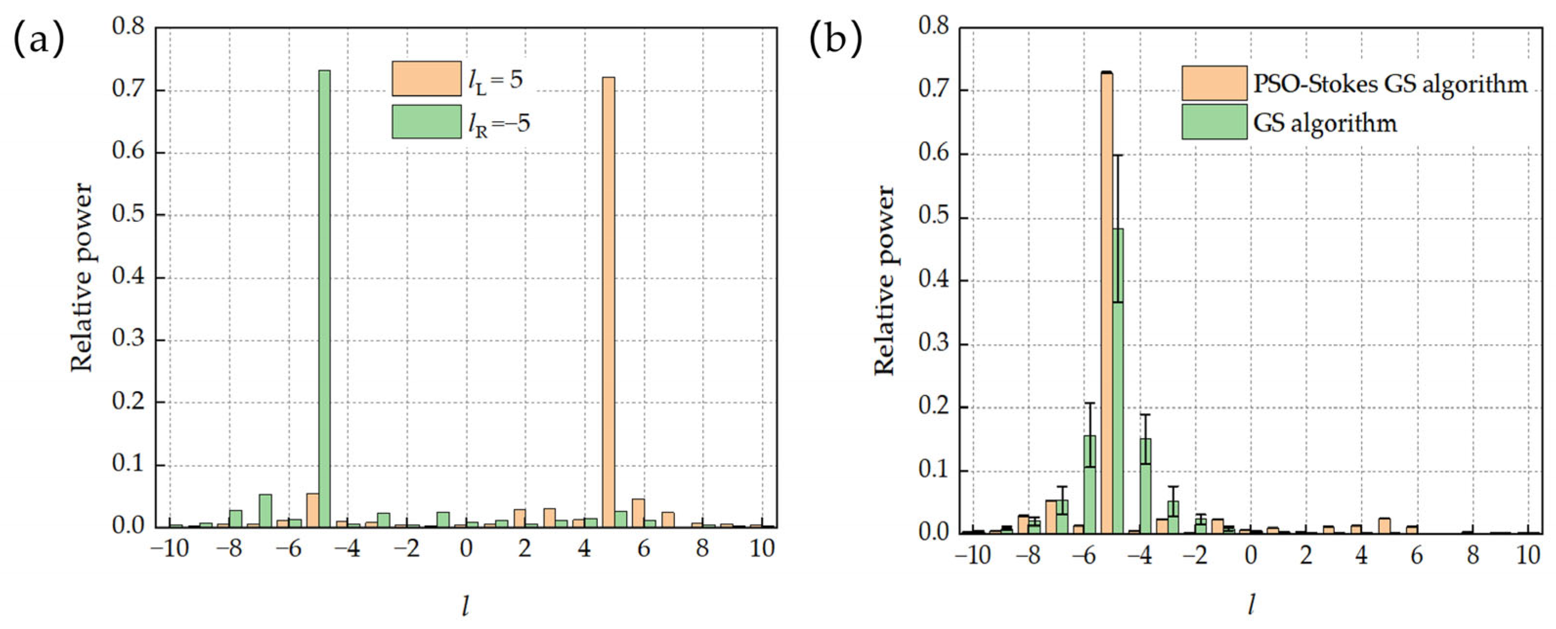
To comprehensively analyse the effectiveness of the Stokes-PSO GS algorithm in recovering distorted optical fields, Figure 7a,b display the orbital angular momentum helical spectra of the restored fields. After algorithmic restoration, the OAM purity for the ±5 orders of the left and right circular polarized components can reach 72.11% and 73.13%, respectively. However, there is a small amount of orbital angular momentum distribution around the opposite topological charges, which is clearly reflected in Figure 7, caused by the Stokes information in the phase screen. Furthermore, based on the definition of Stokes parameters and substrate transformation relation, by adding phase compensation information for the S1 and S2 components containing phase information in diagonal, anti-diagonal, horizontal, and vertical directions in the pre-compensated phase screens, this information can be transformed into compensation for the left and right circular polarized components. Combined with the PSO algorithm, it can further enhance the polarized vortex beam’s field restoration and velocity measurement accuracy. By selecting 70 populations optimized by the Stokes-PSO GS algorithm and the −5 order polarized components obtained through 70 operations of the GS algorithm for angular spectrum analysis, it is evident that the Stokes-PSO GS algorithm exhibits higher angular spectrum purity (compared to the GS algorithm, increasing from 48.31 to 72.93%, and an average relative increase of 33.76%) and lower standard deviation (ρp, GS = 11.62%, ρp, Stokes-PSO GS = 0.005675%). This indicates that the Stokes-PSO GS algorithm demonstrates excellent stability in enhancing the OAM spectrum purity of the optical field.

4.3. Improvement in Velocity Measurement Accuracy

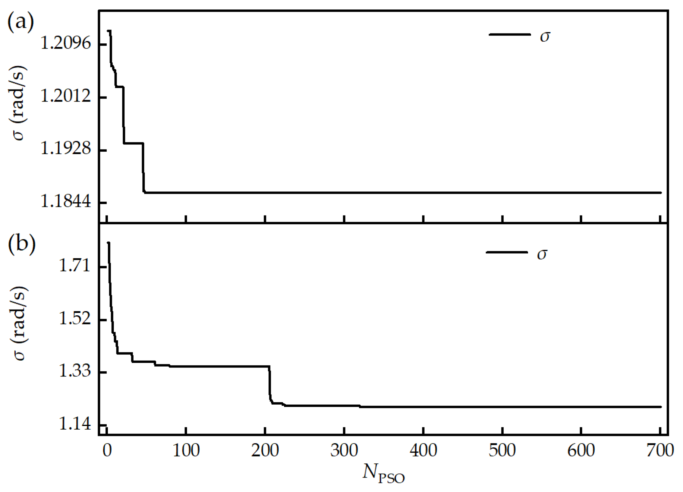
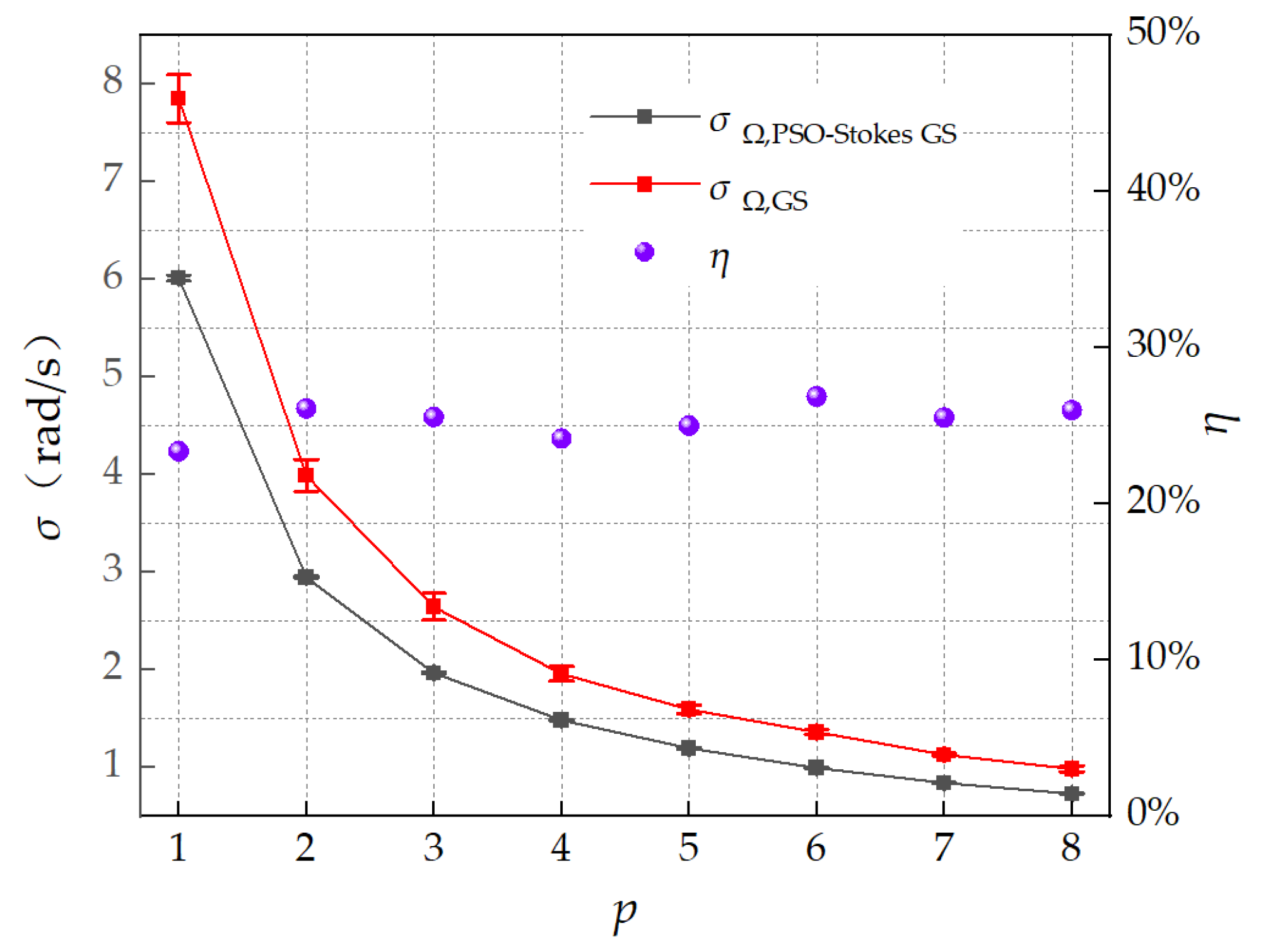
The optimization curves of the velocity measurement accuracy during the iteration process are presented in Figure 8. Because the left- and right-circular components have opposite topological charges, two optimization curves are optimized with the highest and the average velocimetry accuracy of the left and right circular polarized components, respectively, as the fitness functions. The left and right circular polarized components experience a significant decrease in velocity measurement error after 47 and 62 iterations, undergoing several steps of rapid decline. They eventually reach their lowest points after 49 and 320 iterations, stabilizing at 1.207 rad/s and 1.186 rad/s, respectively. After ten operations of calculation, the lowest points are stabilized at 1.192 and 1.184 rad/s in 47 and 353 iterations, with standard deviations of 0.01133 and 0.001124 rad/s, respectively. The difference in velocity measurement accuracy is small, indicating that after optimization, the velocity measurement accuracy of both components is similar. As presented in Table 1, compared to utilizing the conventional GS algorithm, the Stokes-PSO GS algorithm improves the velocity measurement accuracy by 25.93% on average. Compared to the uncompensated scenario, it improves by an average of 29.12%. Finally, the study explores the ability of the Stokes-PSO GS algorithm to improve velocity measurement accuracy for distorted beams at different polarized orders. For polarized vortex beams with opposite topological charges l1, l2 of the left and right circular polarized components, the polarized order p can be represented as p = ( l 1 l 2 ) / 2 . After 20 operations of the Stokes-PSO GS algorithm and comparison with the GS algorithm, as illustrated in Figure 9, it is evident that under different polarized orders, the Stokes-PSO GS algorithm achieves higher mean velocity measurement accuracy (up to 26.89% improvement, with an average improvement of 25.34%) and lower standard deviation (1.121%) compared to the GS algorithm. The improvement rates η are relatively stable, providing further evidence of the stability of the Stokes-PSO GS algorithm. The results indicate that the Stokes-PSO GS algorithm, which utilizes polarization information and particle swarm optimization, can effectively and stably enhance the system’s velocity measurement accuracy for vortex beams propagating through atmospheric turbulence.

5. Discussion

The current research on compensating the distortion vortex beam through turbulence is mainly based on the use of adaptive optics and intelligent optimization algorithms to recover the optical field and improve the OAM purity, except for the introduction of probe beams to detect the distortion wavefront [35]. Rarely research focuses on improving the velocity measurement accuracy of distorted vortex beams after passing through turbulence. As proposed in ref. [23], the GS algorithm is improved by adding additional random phase perturbations in the spatial domain in each iteration, and ref. [26] proposes a model-based wavefront reconstruction method that enables the AO-based CNN algorithm to significantly improve the OAM purity under stronger turbulence intensities. It is worth noting that neither ref. [23] nor ref. [26] introduces new compensation information. Fewer studies have introduced new dimensions and multi-channel compensation information to participate in the algorithm, whereas ref. [36] introduces Fourier-domain information as input information to the Hybrid input–output algorithm (HIOA) to adjust the compensation phase screen in addition to the distorted light intensity, thus achieving a higher OAM purity enhancement (~20% → <70%). It also shows the great potential of introducing new compensation information to enhance the OAM purity. These studies have only focused on the optimization of the OAM purity, whereas this study builds on this by using the OAM spectral information to improve the velocity measurement accuracy. There is a lack of related research introducing the polarization Stokes parameters to assist in improving the optical field and enhancing the rotational velocity accuracy.
In Table 2, our work is compared to several representative studies above. Compared to the algorithms in other works, the highlight of the Stokes-PSO GS algorithm is to introduce the multi-channel polarization Stokes compensation information as references to adjust the phase and amplitude of the pre-compensation phase screen, and further iteratively optimize the screen through the PSO algorithm to obtain better compensation ability. It is the reason that the algorithm boosted the velocity measurement accuracy by 25.93% and increased the OAM purity by 33.76%, compared to the GS algorithm. In addition, the introduction of PSO shapes the stability advantage (σp, Stokes-PSO GS = 0.005675%) of the Stokes-PSO GS algorithm.
In the simulation process of this work, after the preliminary simulation calculations, compared to the genetic algorithm and its variant algorithms which show unstable optimization results, the PSO algorithm is chosen because of its good convergence and stability [37,38]. Severe optical field distortion under excessive turbulence intensity surpasses the compensatory ability of the algorithm, thus limiting the application scope of the algorithm. Moreover, considering the resolution of the phase screen, the parameters need to be set in such a way as to ensure calculation effectiveness and population diversity. The parameters m1, m2, and α of the PSO algorithm have an impact on the convergence of the results. Too large and too small values can cause the random solution to converge slowly or premature convergence to the local optimum. In conclusion, inappropriate parameter values, small population size, and a complex external environment can reduce results reproducibility, resulting in the algorithm’s inability to effectively leverage compensatory ability.
The Stokes-PSO GS algorithm requires the generation of high-quality polarized vortex beams and effective detection of Stokes parameters in the practical experimental process of rotational Doppler velocimetry. The resulting deviation has an impact on the calculation results of the pre-compensated phase screen. Relief can be obtained by improving experimental skills. Additionally, if hardware-accelerated computation methods are not used, the Stokes-PSO GS algorithm requires a long computation time, which still needs to be improved for practical application.
There are many ways to improve the research methodology of this paper in subsequent studies. Adjusting the resolution of the phase screen to a more appropriate level, enlarging the population size, choosing better ways of adjusting parameters (e.g., adaptive adjustment strategy [39]), and imposing constraints on the solution range can improve the global optimization, recover the optical field, enhance the velocimetry accuracy, and control the computation time. Incorporating multi-channel and multi-dimensional information into the algorithm for enhancing compensation, selecting feature areas or setting new evaluation index and other ways to obtain available information are also worth considering. By building a database of optical fields at different turbulence intensities, the introduced compensation information is used to learn with intelligent algorithms, making the algorithm applicable to stronger turbulence. In addition, reducing the background noise interference could further improve the spectral SNR and thus improve the velocity measurement accuracy. The above discussion demonstrates the broad expansion space of the Stokes-PSO GS algorithm.
We will carry out the research work in two aspects. On the one hand, in addition to further optimizing the PSO algorithm to unleash its optimal ability to improve the velocity measurement accuracy, we plan to integrate the adaptive optics compensation, intelligent algorithms, and multi-channel compensation information to improve the compensation ability of the algorithm. This involves adopting a suitable parameter adjustment strategy and reducing computation time. On the other hand, we intend to conduct experiments to improve the algorithm’s effectiveness in actual applications.

6. Conclusions

In summary, the proposed Stokes-PSO GS algorithm’s significant feature lies in its adjustment of the compensation phase and amplitude of the GS phase recovery algorithm’s pre-compensated phase screen based on the Stokes polarization information of the polarized vortex beam. This adjustment enhanced the OAM spectrum purity of the beam’s left and right circular polarized components by the reasonable choice of Stokes compensation information and outstanding optimization of the coefficient matrix with the PSO algorithm. Consequently, the algorithm effectively improved the velocity measurement accuracy. Simulation results demonstrated that the Stokes-PSO GS algorithm enhanced the intensity recovery quality of Stokes parameters by enhancing the uniformly petal-shaped intensity distribution structure. It provides better recovery for both phase singularities and peripheral phase regions of S1 and S2, and its uniformly phase intervals distribution. When applied to a polarized vortex beam with lL = 5 and lR = −5, the algorithm boosted the velocity measurement accuracy by 25.93% and increased the OAM purity by 33.76%, σp, Stokes-PSO GS = 0.005675%, compared to the GS algorithm. Furthermore, under various polarized orders, the velocity measurement accuracy obtained by the Stokes-PSO GS algorithm exhibited an average improvement of 25.34% over the GS algorithm, with a standard deviation of 1.121%. This algorithm demonstrated high stability, excellent optical field recovery quality, and a consistently high improvement rate in velocity measurement accuracy. The method presented in this paper offers researchers a new approach to enhance the compensation effectiveness of distorted optical fields through careful selection and ingenious integration of increasing the dimensions of compensation information with adaptive optics intelligent algorithms to further improve the velocity measurements accuracy. The methodology of this paper is an important inspiration for the future development of compensation strategies that incorporate more multidimensional information and adopt smarter algorithms, as well as for the expansion of their applications, especially for remote free-space rotational velocimetry.

Author Contributions

Conceptualization, H.W. and Z.Z.; methodology, Z.Z.; software, H.W.; validation, H.W., Z.Z., and Y.Z.; formal analysis, H.W.; investigation, H.W.; resources, H.W.; data curation, Y.Z. and R.F.; writing—original draft preparation, H.W.; writing—review and editing, Z.Z.; visualization, H.W.; supervision, Z.Z. and R.F.; project administration, Z.Z. and Q.W.; funding acquisition, Z.Z. and Q.W. All authors have read and agreed to the published version of the manuscript.

Funding

This work was supported by the National Natural Science Foundation of China (Grant No. 62075049) and the Fundamental Research Funds for the Central Universities (FRFCU5710050-722; FRFCU5770500522; FRFCU9803502223; FRFCU5770600723) and the Industry-University Research Cooperation Fund of the Eighth Research Institute of China Aerospace Science and Technology Corporation.

Institutional Review Board Statement

Not applicable.

Informed Consent Statement

Not applicable.

Data Availability Statement

Data underlying the results presented in this paper are not publicly available at this time but may be obtained from the authors upon reasonable request.

Conflicts of Interest

The authors declare no conflict of interest.

Appendix A

Owing to the azimuthal component of the Poynting vector resulting from the rotation of the vortex beam around the optical axis, there was an offset angle γ between the photon’s direction of motion and the optical axis [40]. Upon reflection from a target, this led to a rotational Doppler frequency shift, which can be well explained utilizing the velocity projection model [41,42]. The formula for the rotational Doppler frequency shift in the case of a single-mode vortex beam is:
Δ f = l Ω 2 π ,
Ω represents the rotational velocity of the object. The standard deviation of the spectral peak in laser velocimetry can be expressed as [43]:
σ f = 3 π τ 2 S N R
The standard deviation of angular velocity measurement can be obtained from the error propagation formula as follows:
σ Ω = 6 l τ S N R ,
τ represents the accumulation time of the APD detector, and SNR denotes the signal-to-noise ratio of the velocity measurement system. The signal-to-noise ratio is denoted as S N R = 10 log 10 ( P s i g n a l / P n o i s e ) = 20 log 10 ( A s i g n a l / A n o i s e ) , where   A s i g n a l and A n o i s e represent the spectral amplitudes of the signal and noise components, respectively.
The modal expansion method is commonly employed in studying the rotational Doppler effect of vortex beams. Without any special treatment for the target, the scattered light of various topological charges is approximately uniformly distributed. The received optical field is subjected to angular spectrum analysis, simplifying the optical field and representing it:
E = ε 1 exp ( i 2 π f t ) exp i l 1 Ω t + ε 2 exp ( i 2 π f t ) exp i l 2 Ω t + + ε N exp ( i 2 π f t ) exp i l N Ω t
In the equation, li, for i = 1, 2, 3…, N represents the order of orbital angular momentum contained in the beam after the incident light undergoes angular spectrum dispersion in atmospheric turbulence. εi is the relative power of the li-th order. Based on this, the Fourier transform is performed to extract the Doppler frequency shift values, allowing for the calculation of the object’s rotational velocity and the velocity measurement accuracy.

References

  1. Allen, L.; Beijersbergen, M.W.; Spreeuw, R.; Woerdman, J. Orbital angular momentum of light and the transformation of Laguerre-Gaussian laser modes. Phys. Rev. A 1992, 45, 8185. [Google Scholar] [CrossRef] [PubMed]
  2. Zhang, Z.; Cen, L.; Wang, F.; Zhao, Y. Tiny velocity measurement using the rotating petal-like mode of orbital angular momentum. Opt. Lett. 2021, 46, 4805–4808. [Google Scholar] [CrossRef]
  3. Lavery, M.P.; Speirits, F.C.; Barnett, S.M.; Padgett, M.J. Detection of a spinning object using light’s orbital angular momentum. Science 2013, 341, 537–540. [Google Scholar] [CrossRef] [PubMed]
  4. Anderson, A.Q.; Strong, E.F.; Coburn, S.C.; Rieker, G.B.; Gopinath, J.T. Orbital angular momentum-based dual-comb interferometer for ranging and rotation sensing. Opt. Express 2022, 30, 21195–21210. [Google Scholar] [CrossRef] [PubMed]
  5. Qiu, S.; Ding, Y.; Liu, T.; Liu, Z.; Ren, Y. Rotational object detection at noncoaxial light incidence based on the rotational Doppler effect. Opt. Express 2022, 30, 20441–20450. [Google Scholar] [CrossRef]
  6. Zhang, Y.; Zhang, Z.; Lin, H.; Nie, Z.; Feng, R.; Zhao, Y.; Jia, B. Dual-point noncoaxial rotational Doppler effect towards synthetic OAM light fields for real-time rotating axis detection. Light Adv. Manuf. 2023, 4, 27. [Google Scholar] [CrossRef]
  7. Zhou, H.-L.; Fu, D.-Z.; Dong, J.-J.; Zhang, P.; Chen, D.-X.; Cai, X.-L.; Li, F.-L.; Zhang, X.-L. Orbital angular momentum complex spectrum analyzer for vortex light based on the rotational Doppler effect. Light Sci. Appl. 2017, 6, e16251. [Google Scholar] [CrossRef]
  8. Qiu, S.; Liu, T.; Ren, Y.; Li, Z.; Wang, C.; Shao, Q. Detection of spinning objects at oblique light incidence using the optical rotational Doppler effect. Opt. Express 2019, 27, 24781–24792. [Google Scholar] [CrossRef]
  9. Zhang, Z.; Cen, L.; Zhang, J.; Hu, J.; Wang, F.; Zhao, Y. Rotation velocity detection with orbital angular momentum light spot completely deviated out of the rotation center. Opt. Express 2020, 28, 6859–6867. [Google Scholar] [CrossRef]
  10. Ding, Y.; Liu, T.; Liu, Z.; Qiu, S.; Xu, L.; Ren, Y. Detection of a spinning object with circular procession using an optical vortex beam. Opt. Lett. 2022, 47, 2398–2401. [Google Scholar] [CrossRef]
  11. Deng, J.; Li, K.F.; Liu, W.; Li, G. Cascaded rotational Doppler effect. Opt. Lett. 2019, 44, 2346–2349. [Google Scholar] [CrossRef]
  12. Sha, Q.; Wang, W.; Liu, T.; Liu, Z.; Qiu, S.; Ren, Y. Analysis of rotational velocity measurement accuracy and signal-to-noise ratio of balanced detection based on vortex beam. Infrared Laser Eng. 2021, 50, 20210616-1–20210616-9. [Google Scholar]
  13. Guo, K.; Lei, S.; Lei, Y.; Zhou, H.; Guo, Z. Research on Detecting Targets’ Accelerations Based on Vortex Electromagnetic Wave in Non-Line-of-Sight Scenario. IEEE Sens. J. 2023, 23, 4078–4084. [Google Scholar] [CrossRef]
  14. Guo, K.; Lei, S.; Lei, Y.; Zhou, H.; Guo, Z. Study on detection accuracy of targets’ accelerations based on vortex electromagnetic wave in keyhole space. Chin. Phys. B 2023. [Google Scholar] [CrossRef]
  15. Guo, H.; Qiu, X.; Qiu, S.; Hong, L.; Lin, F.; Ren, Y.; Chen, L. Frequency upconversion detection of rotational Doppler effect. Photonics Res. 2022, 10, 183–188. [Google Scholar] [CrossRef]
  16. Yao, A.M.; Padgett, M.J. Orbital angular momentum: Origins, behavior and applications. Adv. Opt. Photonics 2011, 3, 161–204. [Google Scholar] [CrossRef]
  17. Aftab, M.; Choi, H.; Liang, R.; Kim, D.W. Adaptive Shack-Hartmann wavefront sensor accommodating large wavefront variations. Opt. Express 2018, 26, 34428–34441. [Google Scholar] [CrossRef]
  18. Zhou, S.; Zhang, Q.; Gao, R.; Chang, H.; Xin, X.; Li, S.; Pan, X.; Tian, Q.; Tian, F.; Wang, Y. High-accuracy atmospheric turbulence compensation based on a Wirtinger flow algorithm in an orbital angular momentum-free space optical communication system. Opt. Commun. 2020, 477, 126322. [Google Scholar] [CrossRef]
  19. Fu, S.; Zhang, S.; Wang, T.; Gao, C. Pre-turbulence compensation of orbital angular momentum beams based on a probe and the Gerchberg–Saxton algorithm. Opt. Lett. 2016, 41, 3185–3188. [Google Scholar] [CrossRef] [PubMed]
  20. Song, L.; Lam, E.Y. Fast and robust phase retrieval for masked coherent diffractive imaging. Photonics Res. 2022, 10, 758–768. [Google Scholar] [CrossRef]
  21. Li, M.; Li, Y.; Han, J. Gerchberg–Saxton algorithm based phase correction in optical wireless communication. Phys. Commun. 2017, 25, 323–327. [Google Scholar] [CrossRef]
  22. Dedo, M.I.; Wang, Z.; Guo, K.; Sun, Y.; Shen, F.; Zhou, H.; Gao, J.; Sun, R.; Ding, Z.; Guo, Z. Retrieving performances of vortex beams with GS algorithm after transmitting in different types of turbulences. Appl. Sci. 2019, 9, 2269. [Google Scholar] [CrossRef]
  23. Chang, H.; Yin, X.-l.; Cui, X.-z.; Zhang, Z.-c.; Ma, J.-x.; Wu, G.-h.; Zhang, L.-j.; Xin, X.-j. Adaptive optics compensation of orbital angular momentum beams with a modified Gerchberg–Saxton-based phase retrieval algorithm. Opt. Commun. 2017, 405, 271–275. [Google Scholar] [CrossRef]
  24. Dedo, M.I.; Wang, Z.; Guo, K.; Guo, Z. OAM mode recognition based on joint scheme of combining the Gerchberg–Saxton (GS) algorithm and convolutional neural network (CNN). Opt. Commun. 2020, 456, 124696. [Google Scholar] [CrossRef]
  25. Cao, J.; Zhao, X.; Li, Z.; Liu, W.; Gu, H. Modified artificial fish school algorithm for free space optical communication with sensor-less adaptive optics system. J. Korean Phys. Soc. 2017, 71, 636–646. [Google Scholar] [CrossRef]
  26. Li, Z.; Su, J.; Zhao, X. Atmospheric turbulence compensation with sensorless AO in OAM-FSO combining the deep learning-based demodulator. Opt. Commun. 2020, 460, 125111. [Google Scholar] [CrossRef]
  27. Kumar, N.; Khandelwal, V. Compensation of wavefront aberration using oppositional-breeding artificial fish swarm algorithm in free space optical communication. J. Opt. 2022, 52, 1370–1380. [Google Scholar] [CrossRef]
  28. Gao, Y.; Guan, L.; Wang, T.; Sun, Y. A novel artificial fish swarm algorithm for recalibration of fiber optic gyroscope error parameters. Sensors 2015, 15, 10547–10568. [Google Scholar] [CrossRef]
  29. Li, Z.; Cao, J.; Zhao, X.; Liu, W. Atmospheric compensation in free space optical communication with simulated annealing algorithm. Opt. Commun. 2015, 338, 11–21. [Google Scholar] [CrossRef]
  30. Sun, T.; Hu, J.; Zhu, X.; Xu, F.; Wang, C. Broadband Single-Chip Full Stokes Polarization-Spectral Imaging Based on All-Dielectric Spatial Multiplexing Metalens. Laser Photonics Rev. 2022, 16, 2100650. [Google Scholar] [CrossRef]
  31. Fu, S.; Gao, C.; Wang, T.; Zhang, S.; Zhai, Y. Simultaneous generation of multiple perfect polarization vortices with selective spatial states in various diffraction orders. Opt. Lett. 2016, 41, 5454–5457. [Google Scholar] [CrossRef]
  32. Arlt, J.; Dholakia, K.; Allen, L.; Padgett, M. The production of multiringed Laguerre–Gaussian modes by computer-generated holograms. J. Mod. Opt. 1998, 45, 1231–1237. [Google Scholar] [CrossRef]
  33. Tatarski, V.I. Wave Propagation in a Turbulent Medium; Courier Dover Publications: Mineola, NY, USA, 2016. [Google Scholar]
  34. Lane, R.; Glindemann, A.; Dainty, J. Simulation of a Kolmogorov phase screen. Waves Random Media 1992, 2, 209. [Google Scholar] [CrossRef]
  35. Kishikawa, H.; Kishimoto, H.; Sakashita, N.; Goto, N.; Liaw, S.-K. Pilot beam-assisted adaptive compensation for atmospheric turbulence in free-space optical transmission of beams carrying orbital angular momentum. Jpn. J. Appl. Phys. 2020, 59, SOOD03. [Google Scholar] [CrossRef]
  36. Yin, X.; Chang, H.; Cui, X.; Ma, J.-X.; Wang, Y.-J.; Wu, G.-H.; Zhang, L.; Xin, X. Adaptive turbulence compensation with a hybrid input–output algorithm in orbital angular momentum-based free-space optical communication. Appl. Opt. 2018, 57, 7644–7650. [Google Scholar] [CrossRef]
  37. Van den Bergh, F.; Engelbrecht, A.P. A cooperative approach to particle swarm optimization. IEEE Trans. Evol. Comput. 2004, 8, 225–239. [Google Scholar] [CrossRef]
  38. Hsieh, S.-T.; Sun, T.-Y.; Liu, C.-C.; Tsai, S.-J. Efficient population utilization strategy for particle swarm optimizer. IEEE Trans. Syst. Man Cybern. Part B (Cybern.) 2008, 39, 444–456. [Google Scholar] [CrossRef] [PubMed]
  39. Wei, B.; Xia, X.; Yu, F.; Zhang, Y.; Xu, X.; Wu, H.; Gui, L.; He, G. Multiple adaptive strategies based particle swarm optimization algorithm. Swarm Evol. Comput. 2020, 57, 100731. [Google Scholar] [CrossRef]
  40. Padgett, M.; Allen, L. The Poynting vector in Laguerre-Gaussian laser modes. Opt. Commun. 1995, 121, 36–40. [Google Scholar] [CrossRef]
  41. Belmonte, A.; Torres, J.P. Optical Doppler shift with structured light. Opt. Lett. 2011, 36, 4437–4439. [Google Scholar] [CrossRef] [PubMed]
  42. Ding, Y.; Ding, Y.; Qiu, S.; Liu, T.; Ren, Y. Rotational frequency detection of spinning objects at general incidence using vortex beam (Invited). Infrared And Laser Eng. 2021, 50, 20210451–20210457. [Google Scholar]
  43. Jelalian, A.V. Laser Radar Systems; Artech House Publishers: Norwood, MA, USA, 1992. [Google Scholar]
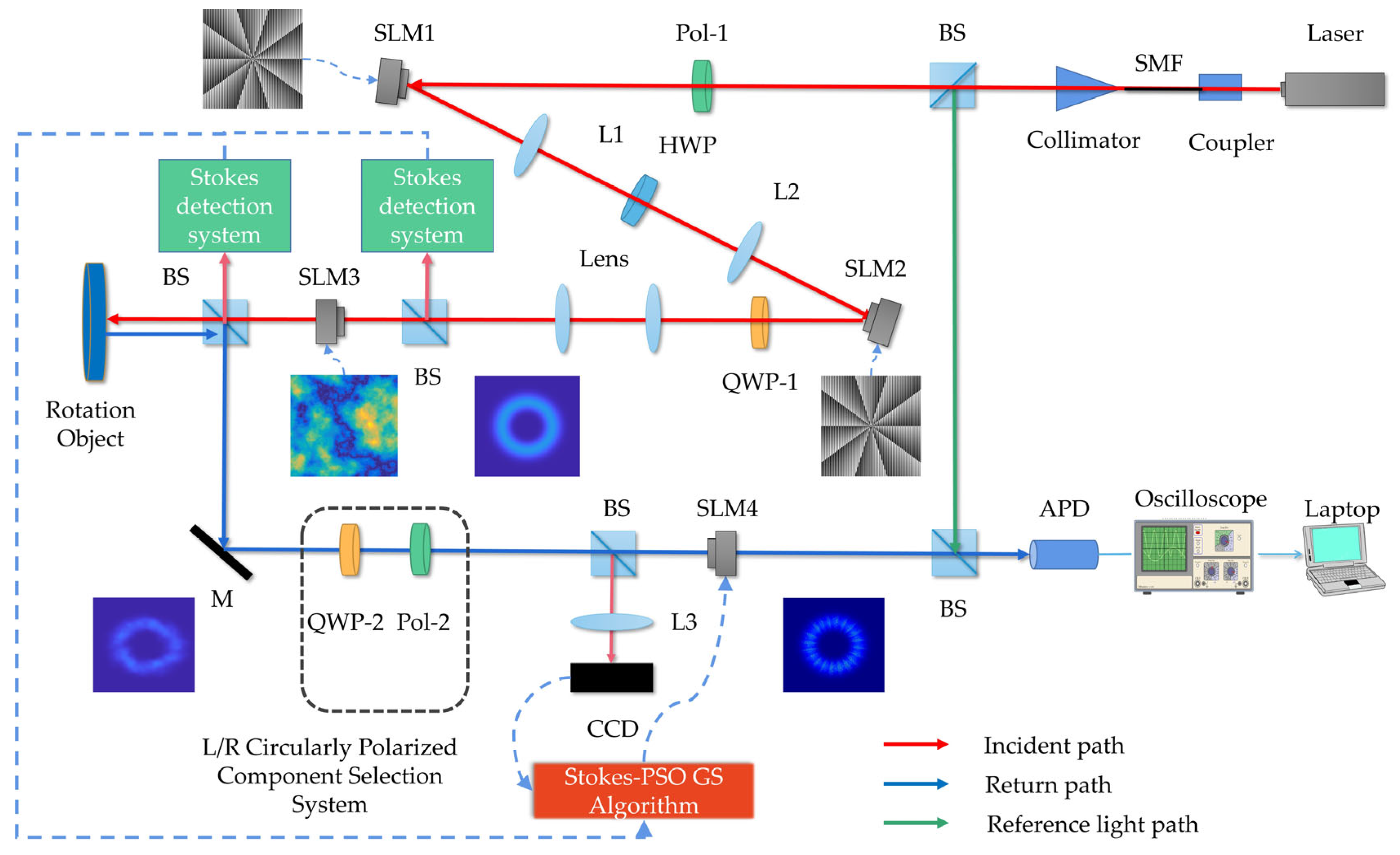
Figure 1. System design diagram.
Photonics 10 01293 g001
Figure 2. Stokes-PSO GS Algorithm Flowchart.
Photonics 10 01293 g002
Figure 3. S1 and S2 components phase diagram of polarized vortex beam obtained by (a,d) non-turbulence, (b,e) Stokes-PSO GS algorithm compensation, and (c,f) GS algorithm compensation. Note that S1 and S2 phases recovered by the Stokes-PSO GS algorithm show a more significant improvement in singularities (marked by red circle for convenient and clear comparison) and peripheral regions compared to the GS algorithm.
Photonics 10 01293 g003
Figure 4. Matrix Γ obtained through PSO optimization. This is used to modulate the fluctuation degree of the pre-compensated phase screen.
Photonics 10 01293 g004
Figure 5. Pre-compensated phase screens for left and right circular polarized components, obtained by (a,b) GS algorithm and (c,d) Stokes-PSO GS algorithm. Note that the Stokes-PSO GS algorithm shows a clear Stokes phase splitting based on the phase screen obtained by the GS algorithm.
Photonics 10 01293 g005
Figure 6. (ad): Stokes parameters in non-turbulence. (eh): Stokes parameters after compensation by Stokes-PSO GS algorithm. (il): Stokes parameters after compensation by GS algorithm. Note that the Stokes parameters recovered by the Stokes-PSO GS algorithm are characterized by a clear uniformly petal-shaped intensity enhancement.
Photonics 10 01293 g006
Figure 7. (a) Orbital angular momentum helical spectra of polarized vortex beam’s left and right circularly polarized components after compensation employing the Stokes-PSO algorithm. (b) Orbital angular momentum helical spectra of lR = −5 component of polarized vortex beam after compensation employing the Stokes-PSO GS algorithm and conventional GS algorithm. Note that the beams recovered from the Stokes-PSO GS algorithm have higher OAM purity and stabilization compared to the GS algorithm but have a small OAM distribution around the opposite topological charge.
Photonics 10 01293 g007
Figure 8. Velocity measurement accuracy optimization curves, utilizing (a) highest and (b) average velocity measurement accuracy for left and right circular polarized components as fitness functions.
Photonics 10 01293 g008
Figure 9. Graph depicting the relationship between polarized order p of beam and velocity measurement accuracy σ after compensation adopting the GS algorithm and Stokes-PSO GS algorithm, along with improvement rate η in velocity measurement accuracy compared to GS algorithm. Note that the recovered beam of the Stokes-PSO GS algorithm has a higher and more stable rotational velocity measurement accuracy.
Photonics 10 01293 g009
Table 1. Velocity measurement accuracy of a beam of uncompensated, GS compensated, Stokes-PSO GS compensated, σΩ, σΩ, GS and σΩ, Stokes-PSO GS, and improvement rate η1, η2 of σΩ, Stokes-PSO GS compared to σΩ and σΩ, GS.
σΩσΩ, GSσΩ, Stokes-PSO GSη1 η 1 ¯ η2 η 2 ¯
1.6761.587 a1.184 a29.36% a29.12%25.39% a25.93%
1.621 b1.192 b28.88% b26.47% b
Note: a and b represent (a) highest and (b) average velocity measurement accuracy for left and right circular polarized components, respectively, which are employed to calculate velocity measurement accuracy.
Table 2. Comparison of previously published works with this work on the OAM purity enhancement in atmospheric turbulence using an intelligent algorithm.
ItemsRef. [23]Ref. [26]Ref. [36]Our Work
AlgorithmSpatial phase perturbation (SPP) GSAO and CNNAO and HIOAStokes-PSO GS
C n 2 5 × 10⁻¹⁵ m−2/31 × 10−13 m−2/33 × 10−14 m−2/31 × 10−14 m−2/3
l3−53lL= 5, lR = −5
OAM purity improvement
(w/o comp d→comp)
<20% → <50% c19% → 61%~20% → <70% c11.51% → 72.93%
Othersz = 100 m
λ = 1550 nm
w = 0.01 m
z = 1.2 km
λ = 1550 nm
w = 0.02 m
z = 500 m
λ = 1550 nm
w = 0.0157 m
zST = 200 m
λ = 532 nm
w = 0.003 m
Note: c represents a specific value not provided in the text. <: less than, ~: approximately; d represents without compensation.
Disclaimer/Publisher’s Note: The statements, opinions and data contained in all publications are solely those of the individual author(s) and contributor(s) and not of MDPI and/or the editor(s). MDPI and/or the editor(s) disclaim responsibility for any injury to people or property resulting from any ideas, methods, instructions or products referred to in the content.