Abstract
The law of the polarization state of Raman fiber amplifier switch in single-core feedback structures is unknown. In this paper, two kinds of optical paths with single-core feedback structures are constructed, namely the Raman amplified Faraday rotating mirror single-core feedback structure (RFA-FRMOP) and the Raman amplified ordinary flat mirror single-core feedback structure (RFA-RMOP). In the process of optical signal amplification involving Raman fiber amplifiers, the polarization dependent gain (PDG) generated by Raman switches is affected by the polarization state, and RFA-FRMOP shows better stability. Surprisingly, polarization analysis of the RFA-FRMOP structure shows that both the ellipticity angle and the long-axis azimuth of the output feedback structure changed less than that of the signal entering the feedback structure. The consistency of the long-axis azimuth variation is the main characteristic of the RFA-FRMOP structure. It is found that the variation of the azimuth of the long axis of the RFA-FRMOP structure is obviously greater than that of the ellipticity. These conclusions provide a theoretical basis for the polarization dependent application of Raman fiber amplifiers in single-core feedback structures.
1. Introduction
Raman fiber amplifier (RFA) is a very useful signal amplifier in communication engineering. With the continuous development of wavelength division multiplexing in optical fiber communication, Raman fiber amplifier, which is indispensable in long-distance transmission, has been the focus of research. The Raman effect in fiber is a nonlinear phenomenon that results from molecular vibration, and is responsible for transferring energy from the pump wave to the Stokes wave with the frequency redshift. In single-mode fiber, the Raman gain usually depends on the relative polarization state between the pump and Stokes. The study of the polarization state during Raman switching has become an important problem. Kawakami et al. used a multi-pumped laser source depolarizer to suppress strong noise in a forward-pumped Raman amplifier []. Zhang et al. investigated spontaneous Raman scattering in low-mode fibers: dependence on polarization and spatial patterns [] Therefore, it is very meaningful to study the polarization correlation in Raman amplification.
The Faraday rotating mirror (FRM) consists of a 45° Faraday rotator and a mirror, which makes the Faraday rotator widely used in many polarization studies []. Kiselev et al. have disclosed a method for obtaining polarization-insensitive phase-only modulation using a Faraday rotating mirror that preserves the state and polarization of light modulated using a controlled birefringent medium []. Li et al. proposed and demonstrated a fiber loop-fading sensor based on S fiber taper cascaded Faraday rotating mirror for measuring refractive index []. Zhang et al. propose a polarization-insensitive cyclic delay self-heterodyne measurement method that effectively reduces polarization-induced fading without any active polarization control through uniquely combining Faraday rotating mirrors in an interferometer []. Lin et al. used a non-reciprocal phase shifter consisting of two quarter-wave plates and a Faraday rotator to introduce the phase bias between back-propagating beams in a nonlinear amplifying ring mirror []. A 1.7 µm doped tm ultrafast fiber laser was fabricated. Shi et al. designed a spectral optimized non-polarized tilted fiber Bragg grating surface plasmon resonance sensor using a Faraday rotating mirror []. Lee et al. propose a polarization diversity loop based fiber-interleaving filter to provide polarization control over the free spectral range []. Because of the shortcomings of traditional optical fibers in interferometry, especially the practical limitations of not being able to lay a straight line single-axis, a single-core feedback structure is proposed. It is characterized by the use of only one fiber, [] and the end of the sensing fiber is connected with a mirror, which can be extended all the way down to reflect the light source transmitted to the end of the fiber back to the sensing fiber. This structure is applied to pipeline monitoring and other aspects. Xiao et al. propose a new all-fiber speed interferometer based on an optical feedback delay line using a single-core feedback structure, which fundamentally eliminates the distributed phase modulation noise of the delay line [].
However, the polarization state of Raman amplifiers in this structure has not been studied in detail. Although single-core feedback structures are found to have polarization stability, the specific polarization dependent gain (PDG), polarization angle, and specific parameter changes have not been studied in detail. Therefore, we investigated the polarization state in the Raman amplified Faraday rotating mirror single-core feedback structures, (RFA-FRMOP) and in the Raman amplified ordinary flat mirror single-core feedback structure (RFA-RMOP). In the study of polarization, Poincare sphere was used to analyze the polarization state, as well as calculate the change of the azimuth and ellipticity of the major axis.
2. Measurement Principle
Raman dependent gain in single-mode fibers has been extensively studied, and we can use the following formula to calculate Raman switching gain as polarization dependent gain (PDG) []. PDG of RFA refers to the characteristic that RFA gain changes with the polarization angle of the signal light (SL) and the pump light (PL), which is called the polarization dependent gain of RFA. RFA gain Gr usually refers to the Raman switch gain (Gon-off). Here we use Gon-off to represent PDG, which is the ratio of the output power Prs of the RFA pump light on, and the output power Ps of the RFA pump light off, in dBm, as shown in Formula (1). According to the theoretical model proposed by YASUHIRO AOKI [], the Raman switching gain Gr can also be expressed as a formula related to the pump light and the Raman gain coefficient. Among them, gr is the Raman gain coefficient, which is a constant related to the core material, Pp is the pump optical power, Aeff is the effective core area, which is related to the effective core radius, Leff represents the effective length, which is related to the pump optical loss coefficient and transmission distance. Keff represents the polarization correlation coefficient, which is related to PDG. Thus, the PDG of working light (WL) is polarization-selective.
Gon-off = 10·lg (Prs/Ps) = exp((gr Pp Leff)/(Aeff Keff)),
The Poincare sphere in both switched Raman states, as shown in Figure 1, can represent the polarization state of working light. S0 represents the intensity of polarized working light, and positive S1 represents the horizontal (X-axis direction) linear polarized light component; the positive S2 represents the linearly polarized working light component in the direction of 45°; Positive S3 indicates the right-handed circularly polarized working light component. The negative values of S1, S2, and S3 represent vertical line polarized working light, −45° linear polarized working light, and left-handed circular polarized working light that are orthogonal to above polarized light states. With the polarization analyzer, we can get S1, S2, S3, and DOP.
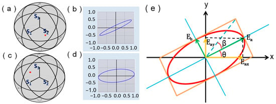
Figure 1.
Poincare sphere represents the polarization state. (a) The coordinate point of the working light polarization state on the Poincare sphere when the Raman fiber amplifier is off; (b) The elliptical shape of the working light polarization state when the Raman fiber amplifier is off; (c) The coordinate point of the working light polarization state on the Poincare sphere when the Raman fiber amplifier is on; (d) The elliptical shape of the working light polarization state when the Raman fiber amplifier is on; (e). Schematic diagram of polarized working light analysis.
When only the polarization state is of interest, usually for S0 normalization process, that is, remove the non-polarized part of the polarized working light. A Poincare sphere can express any polarization state of working light corresponding to a specific Stokes parameter or a point coordinate, then Stokes parameters satisfy Formula (3).
Among them, β represents the ellipticity angle of elliptically polarized working light, which refers to the inverse tangent value of the ratio of the short axis component and the long axis component of the ellipse, as shown in Formula (4); θ represents the azimuth of the long axis of the elliptically polarized working light, that is, the angle formed between the long axis of the ellipse and the X-axis of the fiber, which is numerically equal to the ratio of the components on the y axis and the X-axis, as shown in Formula (5). The diagram of β and θ is shown in Figure 1e.
Assuming that the ellipticity angles before and after the polarization state change are β0 and β, and the azimuth angles are θ0 and θ respectively, then their differences Δβ and Δθ can be used to represent the degree of elliptic shape change, and the angle of elliptic rotation of the elliptically polarized working light, as shown in Formulas (6) and (7).
Δβ = |β − β0|,
Δθ = |θ − θ0|,
We can use the absolute value of the change in angle to describe the change in polarization state.
3. Optical Path Structure
The optical path structure we used to study the polarization state change in the single-core feedback structure through Raman switching is shown in Figure 2. We set up two sets of optical path structures, RFA-FRMOP and RFA-RMOP, to measure the signal power and polarization state in and out of the feedback structure.
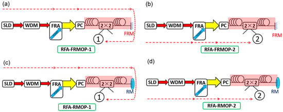
Figure 2.
Optical path structure. (a) Working light measuring device entering a feedback structure in the RFA-FRMOP optical path; (b)Working light measuring device output a feedback structure in the RFA-FRMOP optical path; (c) Working light measuring device entering a feedback structure in the RFA-RMOP optical path; (d) Working light measuring device with output feedback structure in RFA-RMOP optical path.
In the first set of experiments, the signal light (SL, the red arrow in Figure 2) was provided by a Super Light Emitting diode (SLD, the central wavelength is 1550 nm, the power is 8.869 mW), and the signal light was passed through a wavelength division multiplexing filter (WDM) to obtain signal light with a wavelength of 1551–1555 nm. The signal light passed through a Raman fiber amplifier, and propagated to a manually adjusted polarization controller (PC). The pump light (PL, the blue arrow in Figure 2) generated in the amplifier, as well as the signal light, travel in the same direction through the fiber, and the pump wavelength was 1450 nm. The pump current was set at 200 mA, and the pump power was 700 mW. The pump light and signal light passed through the polarization controller at the same time, and turned into working light (WL, the Large yellow arrow in Figure 2) with a wavelength of 1551–555 nm. Then, the working light was amplified using two gain fibers. In the first gain fiber (single-mode fibers, G.625), the signal light propagated in the same direction as the pump wave to generate Raman gain, and the optical signal was enhanced. Then, the working light entered the 2 × 2 coupler, and the working light entering the feedback optical path was measured at the coupler output end 2. The instrument used here was the wavelength division multiplexing filter (1551–555 nm) connected at end 2, then connected to the polarization analyzer (PA) (Keysight N7788-C), as shown in Figure 2b. We obtained the polarization state of the working light before we entered the feedback structure. The working light passing through the 2 × 2 coupler entered the second gain fiber (single-mode fibers, G.625), then was reflected by the Faraday rotating mirror, and then reversed into the second gain fiber. The signal light was amplified twice, reversed into the 2 × 2 coupler, which was received through end 1. The measuring instrument and connection mode of end 1 was the same as that of end 2, as shown in Figure 2a. Thus, we obtained the polarization state of the output feedback structure. In the second group of experiments, the reflector of the device was changed to an ordinary flat mirror (central reflection wavelength is 1550 nm), and other devices were the same as those of the first group, as shown in Figure 2c,d.
4. Experimental Results
The polarization controller (PC) that we used consists of three discs wrapped around a single-mode fiber, all of which could be turned. We set three polarization states for each disk, and the initial state of the three disks was perpendicular to the desktop. It was rotated 0°, rotated 90° to the left, and rotated 90° to the right. A total of 27 polarization-states-change-order (PSCO) could be adjusted (Pi, i = 1, 2, …, 27). We set the first gain fiber length D1, and the second paragraph gain fiber length D2. We set the D1, D2 to 0–60 km, 10–50 km, 20–40 km, 30–30 km, 40–20 km, 50–10 km, 60–0 km for a total of seven kinds of length (D0-60, D10-50, D20-40, D30-30, D40-20, D50-10, D60-0). We measured the switching power (Prs, Ps) in 27 polarization states at ends 1 and 2 of the RFA-FRMOP optical path, and the RFA-RMOP optical path at each length D1-D2. We obtained 1512 polarization power values, and calculated 756 PDG results in the RFA-FRMOP optical path and the RFA-RMOP optical path. The PDG results in the D0-60 and D20-40 state are shown in Figure 3. It can be seen that the variation of scatter distribution of polarized gain of the RFA-FRMOP optical path is similar to that of RFA-RMOP optical path. For example, Figure 3e–h. Since the distribution of D10-50, D20-40, D30-30, D40-20, D50-10, D60-0 is similar to that of D20-40, we will not expand the details, and we will take the mean value of the 27 PDG at the first and second terminals for statistical results, as shown in Figure 3i. The mean polarization-related gain of the first terminal and the second terminal gradually increased and became stable.
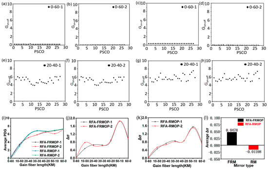
Figure 3.
Polarization-dependent gain. (a) PDG results at end 1 of the RFA-FRMOP optical path in D0-60 state; (b) PDG results at end 2 of the RFA-FRMOP optical path in D0-60 state; (c) PDG results at end 1 of the RFA-RMOP optical path in D0-60 state; (d) PDG results at end 2 of the RFA-RMOP optical path in D0-60 state; (e) PDG results at end 1 of the RFA-FRMOP optical path in D20-40 state; (f) PDG results at end 2 of the RFA-FRMOP optical path in D20-40 state; (g) PDG results at end 1 of the RFA-RMOP optical path in D20-40 state; (h) PDG results at end 2 of the RFA-RMOP optical path in D20-40 state; (i) PDG trend of four ends; (j) σ of RFA-FROMP structure; (k) σ of RFA-ROMP structure; (l) The average Δσ of two types of feedback structures.
Since the PDG is a discrete point, we calculated the population standard deviation σ for the PDG in each case. We plotted it as a curve, and the results of RFA-FRMOP and RFA-RMOP are shown in Figure 3j,k, respectively. In order to more clearly see the difference between the two in terms of stability, we used Δσ (Δσ = σ2 − σ1) to indicate the stability effect of the feedback structure on the signal, and we calculated the values of Δσ at seven distances (Δσ0-60, Δσ10-50, Δσ20-40, Δσ30-30, Δσ40-20, Δσ0-60). The average value of the change in the average global standard deviation (average Δσ) of the feed-structures of RFA-FRMOP and RFA-RMOP was obtained by taking the average value of 7 cases, as shown in Figure 3l. Through the analysis of the degree of dispersion, we can see that the value of RFA-FRMOP is 0.0478, while the value of RFA-RMOP is −0.01598. Compared with RFA-RMOP, RFA-FRMOP has an obvious stabilizing effect on PDG.
For the experiment of polarization state, we measured S1, S2, S3, and DOP of 27 polarization-states-change-order (PSCO) at ends 1 and 2 of the RFA-FRMOP optical path and the RFA-RMOP optical path, respectively, under each length D1-D2. 1512 sets of polarization state values in the RFA-FRMOP optical path and the RFA-RMOP optical path were obtained. 756 ellipticity angular variations Δβ and 756 long-axis azimuth variations Δθ were calculated. The angular ellipticity variation of the the RFA-FRMOP optical path is shown in Figure 4, and the angular ellipticity variation of the RFA-RMOP optical path is shown in Figure 5. The average values of the variations under 7 different distances were taken for statistics, as shown in Figure 4h and Figure 5h. The angular variation of ellipticity in the RFA-FRMOP and RFA-RMOP optical path presents an irregular state.
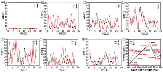
Figure 4.
Ellipticity angle change with polarization state in RFA-FRMOP structure. (a) Changes in Δβ at 1 and 2 ends in the D0-60 state, (b) changes in Δβ at 1 and 2 ends in the D10-50 state, (c) changes in Δβ at 1 and 2 terminals in the D20-40 state, and (d) changes in Δβ at 1 and 2 ends in the D30-30 state, (e) The change of Δβ at ends 1 and 2 in the D40-20 state, (f) the change of Δβ at ends 1 and 2 in the D50-10 state, (g) the change of Δβ at ends 1 and 2 in the D60-0 state, (h) The result of averaging the RFA-FRMOP optical path at different distance states.
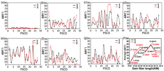
Figure 5.
Ellipticity angle change with polarization state in RFA-RMOP structure. (a) Changes in Δβ at 1 and 2 ends in the D0-60 state, (b) changes in Δβ at 1 and 2 ends in the D10-50 state, (c) changes in Δβ at 1 and 2 ends in the D20-40 state, and (d) changes in Δβ at 1 and 2 ends in the D30-30 state, (e) The change of Δβ at ends 1 and 2 in the D40-20 state, (f) the change of Δβ at ends 1 and 2 in the D50-10 state, (g) the change of Δβ at ends 1 and 2 in the D60-0 state, (h) The result of averaging the RFA-RMOP optical path at different distance states.
Figure 6 shows the azimuth change of the long axis of the RFA-FRMOP optical path. Figure 7 shows the azimuth change of the long axis of the RFA-RMOP optical path. The average value of the variation was taken for statistics, as shown in Figure 6h and Figure 7h. In the RFA-FRMOP optical path, the azimuth change of the long axis presents a consistent change state, and the two curves almost coincide, indicating that the change of the first end is synchronized with the change of the second end.
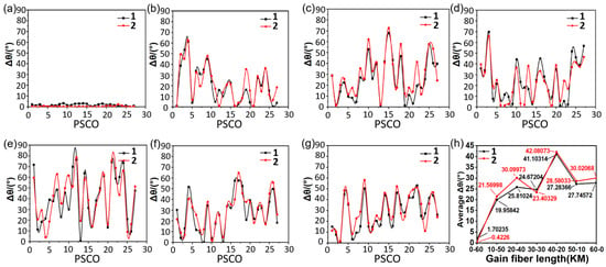
Figure 6.
Major axis azimuth change with polarization state in RFA-FRMOP structure. (a) Changes in Δβ at 1 and 2 ends in the D0-60 state, (b) changes in Δβ at 1 and 2 ends in the D10-50 state, (c) changes in Δβ at 1 and 2 ends in the D20-40 state, and (d) changes in Δβ at 1 and 2 ends in the D30-30 state, (e) The change of Δβ at ends 1 and 2 in the D40-20 state, (f) the change of Δβ at ends 1 and 2 in the D50-10 state, (g) the change of Δβ at ends 1 and 2 in the D60-0 state, (h) The result of averaging the RFA-FRMOP optical path at different distance states.
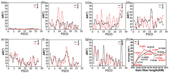
Figure 7.
Major axis azimuth change with polarization state in RFA-RMOP structure. (a) Changes in Δβ at 1 and 2 ends in the D0-60 state, (b) changes in Δβ at 1 and 2 ends in the D10-50 state, (c) changes in Δβ at 1 and 2 ends in the D20-40 state, and (d) changes in Δβ at 1 and 2 ends in the D30-30 state, (e) The change of Δβ at ends 1 and 2 in the D40-20 state, (f) the change of Δβ at ends 1 and 2 in the D50-10 state, (g) the change of Δβ at ends 1 and 2 in the D60-0 state, (h) The result of averaging the RFA-RMOP optical path at different distance states.
In the RFA-RMOP optical path, the azimuth change of the long axis presents a state of irregular change, no obvious pattern was observed.
5. Discussion
In the third part, the optical path structure we have shown is a feedback type. The signal optical transmission direction entering the feedback structure is the same as the pump optical transmission direction, which belongs to the same direction of pumping; the signal optical transmission direction of the output feedback structure is opposite to the pump optical transmission direction, which belongs to the opposite direction of pumping. Therefore, we can refer to the transmission equation of the working light amplified by RFA, which includes both the same direction and opposite direction pumping, as shown in Equation (8) [,,]. Where + and − represent the optical transmission direction, α represents the transmission loss in the fiber, γ is the Rayleigh scattering coefficient. gr (v-ζ) represents the Raman gain coefficient between the frequencies v and ζ. Keff is the polarization correlation coefficient between the pump and the working light, Aeff is the effective mode area, h is the Planck constant, k is the Boltzmann constant, and T is the absolute fiber temperature. The main parameters gr, Aeff, Keff are all associated with Formula (1). Therefore, the PDG tested by our experiment can effectively illustrate the magnification effect of the working light. Moreover, in the experiment, the angle change corresponding to each PDG result were obtained from the polarization analyzer at the same time as Prs and Ps in Formula (1), so the polarization angle change is closely related to PDG.
In the experimental results of the fourth part, we can observe that the Δβ and Δθ measured by the four ends were affected by the change of polarization state, and the polarization state Δβ and Δθ will fluctuate significantly with each change. Since the polarization controller we used is composed of single-mode fiber, and adjusted by manual rotation, we cannot preset the specific change of polarization state. We can measure Δβ and Δθ simultaneously by changing the polarization state several times, so we can measure the angle change produced by switching Raman in some of the same polarization states. We counted the angular variation of ellipticity, and the azimuth of the long axis under the four optical paths in Figure 2, and averaged all points in Figure 4h, Figure 5h, Figure 6h and Figure 7h to get the bar chart in Figure 8. In this way, the overall situation of angle variation in different feedback structured light paths can be explained to a certain extent, and the results are shown in Figure 8. In Figure 8, we can see that FRMOP-Δβ1 is 18.55431 and FRMOP-Δβ2 is 20.56959. This shows that the feedback structure reduces the angular variation of ellipticity, which reflects the stability of FRMOP structure. FRMOP-Δθ1 is 24.03937 and FRMOP-Δθ2 is 25.16819. This shows that the feedback structure makes the long-axis azimuth change smaller, also reflects the stability of FRMOP structure. On the whole, the value of FRMOP-Δβ is smaller than FRMOP-Δθ, indicating that the variation of the ellipticity angle in RFA-FRMOP structure is generally small, indicating that the stability of the ellipticity angle is an important factor in the stability of polarization-related gain. But the RMOP results show no such pattern. This partly explains the results of Figure 3l.
ΔΔβ = |Δβ1 − Δβ2|,
ΔΔθ = |Δθ1 − Δθ2|,
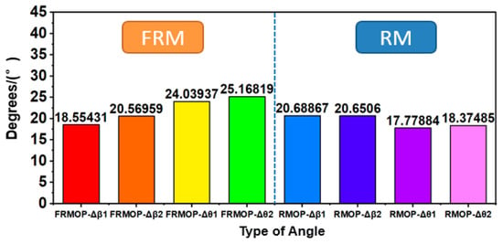
Figure 8.
The average value of the change in ellipticity angle and the change in azimuth of the long axis.
In order to explain the variation rules of polarization parameters in the RFA-FRMOP optical path and the RFA-RMOP optical path shown in Figure 4, Figure 5, Figure 6 and Figure 7, we compared the optical path data of Faraday rotating mirror and ordinary flat mirror, and analyzed the variation relationship between the ellipticity angle and the long-axis azimuth angle difference. By comparing the difference between curve 1 and curve 2, the difference and synchronicity of the changes of the two curves were better reflected. We calculated the difference between the angular change of ellipticity ΔΔβ, and the difference between the azimuth change of the long axis ΔΔθ, and the results shown in Figure 9. Δβ1 represents the angular change in ellipticity of end 1, Δβ2 represents the angular change in ellipticity of end 2, Δθ1 represents the angular change in ellipticity of end 1, and Δθ2 represents the angular change in ellipticity of end 2. As shown in Formulas (10) and (11), The results for ΔΔβ can be seen in Figure 9a, and the results for ΔΔθ can be seen in Figure 9b. Comparing the ordinates of the two figures, we can see that ΔΔβ is about twice as large as ΔΔθ, indicating that the change of Δβ is more chaotic in general, consistent with the situation in Figure 4 and Figure 5, the synchronization and correlation between end 1 and end 2 are low. In Figure 9b, it can be seen that the changes of Δθ are relatively synchronized under the action of both different mirrors. From the black curve, consistent with the situation in Figure 6, it can be seen that the value of ΔΔθ is at the lowest level in the RFA-FRMOP structure, indicating that the angle change shows the most obvious consistent change. By averaging the results of Figure 9a,b, then making a bar chart as shown in Figure 9c, it can be seen that the value of RFA-FRMOP-ΔΔθ is 1.85697, which is also the smallest. This indicates that the variation of Δθ in the RFA-FRMOP structure is very synchronized, which is consistent with the coincidence of 1, 2 curves shown in Figure 6. This also reveals the deep-seated reason for the good PDG stability in Figure 3l. RFA-FRMOP structure, that is, the consistent change of long-axis azimuth variation is an important factor for the PDG stability in the Raman amplification single-core feedback structure based on Faraday rotating mirror.

Figure 9.
Analysis of difference of azimuth change and ellipticity change of long axis. (a) Variation of ΔΔβ with length of gain fiber in RFA-FRMOP and RFA-RMOP structures; (b) The variation of ΔΔθ with the length of gain fiber in RFA-FRMOP and RFA-RMOP structures; (c) Histogram of the mean value of the difference in angle change.
Because the difference between RFA-FRMOP and RFA-RMOP is the difference in the mirrors, this phenomenon is attributed to the rotating effect of the Faraday rotating mirror on the polarized light. We let the point adjacent to FRM on the fiber be A, the working light entering FRM from A be pass light, and the working light reflected from FRM into the fiber be reflect light. The pass optical power can be decomposed into orthogonal P‖pass and P⊥pass, and the reflect optical power can be decomposed into P‖reflect and P⊥reflect, ‖ and ⊥, representing Raman dominant polarization state and orthogonal polarization state respectively. When Raman fiber amplifier is off, this shown in Figure 10a [].

Figure 10.
Polarization changes of RFA-FRMOP. (a) Raman fiber amplifier is off, (b) Raman fiber amplifier is on; A, B, and C in the yellow circle represent a certain location on the fiber.
Due to the characteristics of FRM, the polarization state of the reflect light at point A is the result of the rotation of the pass light polarization state by π/2. If the FRM loss is ignored, the pass light and reflect light component power meet (11).
In Figure 10b, we show FRA when enabled. At this time, due to the polarization gain characteristics of FRA, the light component of the dominant polarization state receives a Raman gain of g‖, and the light component of the orthogonal polarization state receives a Raman gain of g⊥, then the pass light component at A satisfies Equation (12).
After the working light is reflected by FRM, the reflecting light component arriving at A satisfies Equation (13), and the ratio of components satisfies Equation (14) due to polarization rotation.
From Equation (14), it can be found that no matter whether the Raman fiber amplifier is turned on or not, the optical power ratio of the two polarization components of the reflect light reaching A after FRM reflection is the same, and the polarization state will not change at this time. This is consistent with Figure 6. For the problem of the smallest change in ΔΔθ observed in Figure 9c, we made the following additions. The Δθ measured in our experiment is generally greater than the Δβ. The change of polarization state is very sensitive to the outside world. Although we have fixed the entire optical path during the measurement, the polarization state is still affected by temperature, sound vibration, instrument loss, and other small perturbations. For larger Δθ, the proportion of perturbations is small. Therefore, a smaller difference in the variation of long-axis azimuth indicates a higher agreement between the first and second ends of the RFA-FRMOP structure and Equation (14). However, for smaller Δβ, the proportion of perturbations may be large, so we do not see a very clear contrast between RFA-FRMOP and RFA-RMOP in Figure 9a.
6. Conclusions
In general, by studying the polarization state of the RFA-FRMOP optical path and the RFA-RMOP optical path, the experimental conclusion shows that the change consistency of long-axis azimuth is the most prominent feature in the RFA-FRMOP structure. We find that the azimuth change of the major axis is obviously larger than that of the ellipticity. Our experimental results, and theory of the polarization state of the Raman fiber amplifier in single-core feedback structure, can be used in the research and development of sensors, amplifiers, lasers, polarization Scrambler, etc., and provide a basis for the study of the polarization state of these instruments [,,].
Author Contributions
Conceptualization, F.Y. and Y.M.; methodology, F.Y.; software, F.Y. and X.L.; validation, F.Y.; formal analysis, K.J. and Q.X.; investigation, F.Y.; data curation, F.Y.; writing—original draft preparation, F.Y.; writing—review and editing, F.Y.; visualization, Q.X.; supervision, Q.X.; project administration, B.J. All authors have read and agreed to the published version of the manuscript.
Funding
This research received no external funding.
Institutional Review Board Statement
Not applicable.
Informed Consent Statement
Not applicable.
Data Availability Statement
If you need detailed data, please contact Fudan University Optical Fiber Research Center, No. 220, Handan Road, Yangpu District, Shanghai.
Conflicts of Interest
The authors declare no conflict of interest.
References
- Kawakami, H.; Kuwahara, S.; Kisaka, Y. Suppression of Intensity Noises in Forward-pumped Raman Amplifier Utilizing Depolarizer for Multiple Pump Laser Sources. J. Light. Technol. 2021, 39, 7417–7426. [Google Scholar] [CrossRef]
- Zhang, Z.Z.; Cheng, H.T.; Guo, C.; Cui, L.; Zhang, Y.C.; Mo, Q.; Yu, H.; Vasilyev, M.; Li, X.Y. Investigation of Spontaneous Raman Scattering in Few-Mode Fibers: Dependence on Polarization and Spatial Modes. J. Light. Technol. 2021, 39, 6281–6287. [Google Scholar] [CrossRef]
- Sun, L.; Jiang, S.B.; Marciante, J.R. All-Fiber Optical Faraday Mirror Using 56-wt%-Terbium-Doped Fiber. IEEE Photonics Technol. Lett. 2010, 22, 999–1001. [Google Scholar] [CrossRef]
- Kesaev, V.V.; Kiselev, A.D. Phase-only modulation of light. Opt. Lett. 2020, 45, 6703–6706. [Google Scholar] [CrossRef] [PubMed]
- Li, X.Y.; Wang, X.; Niu, P.P.; Zhao, J.F.; Zhang, C.; Gu, E.D. Refractive index measurement using OTDR-based ring-down technique with S fiber taper. Opt. Commun. 2019, 446, 186–190. [Google Scholar] [CrossRef]
- Gao, J.; Jiao, D.D.; Deng, X.; Liu, J.; Zhang, L.B.; Zang, Q.; Zhang, X.; Liu, T.; Zhang, S.G. A Polarization-Insensitive Recirculating Delayed Self-Heterodyne Method for Sub-Kilohertz Laser Linewidth Measurement. Photonics 2021, 8, 137. [Google Scholar] [CrossRef]
- Lin, Z.W.; Chen, J.X.; Li, T.J.; Zhan, Z.Y.; Liu, M.; Li, C.; Luo, A.P.; Zhou, P.; Xu, W.C.; Luo, Z.C. 1.7 mu m figure-9 Tm-doped ultrafast fiber laser. Opt. Express 2022, 30, 32347–32354. [Google Scholar] [CrossRef] [PubMed]
- Lee, S.L.; Kim, J.; Choi, S.; Kim, M.S.; Kim, D.; Lee, Y.W. Polarization-diversified-loop-based optical fiber interleaving filter with polarization-controlled free spectral range. Opt. Commun. 2020, 463, 125345. [Google Scholar] [CrossRef]
- Shi, X.N.; Zhao, W.C.; Zhu, Y.; Shen, C.Y.; Zeng, X.L. Polarization-independent tilted fiber Bragg grating surface plasmon resonance sensor based on spectrum optimization. Opt. Lett. 2023, 48, 3375–3378. [Google Scholar] [CrossRef] [PubMed]
- Jia, B.; Xiao, Q. Method for Monitoring Long-Distance Pipeline of Single-Core Feedback Optical Fiber Interference Structure, Involves Generating Interference Signal Generated by Optical Fiber by Selection of Working Point of Modulating Signal. CN102033226-A; CN102033226-B. 2011-G05571. Available online: https://webofscience.clarivate.cn/wos/alldb/full-record/DIIDW:2011G05571 (accessed on 20 November 2023).
- Hong, G.W.; Lin, P.; Xiao, Q. A Novel all-fiber velocity interferometer based on optic-feedback delay line. Microw. Opt. Technol. Lett. 2012, 54, 1814–1817. [Google Scholar] [CrossRef]
- Stolen, R.H.; Ippen, E.P. Raman gain in glass optical waveguides. Appl. Phys. Lett. 1973, 22, 276–278. [Google Scholar] [CrossRef]
- Aoki, Y. Properties of fiber Raman amplifiers and their applicability to digital optical communication systems. J. Light. Technol. 1988, 6, 1225–1239. [Google Scholar] [CrossRef]
- Kidorf, H.; Rottwitt, K.; Nissov, M.; Ma, M.; Rabarijaona, E. Pump interactions in a 100-nm bandwidth Raman amplifier. IEEE Photonics Technol. Lett. 1999, 11, 530–532. [Google Scholar] [CrossRef]
- Min, B.; Lee, W.J.; Park, N. Efficient formulation of Raman amplifier propagation equations with average power analysis. IEEE Photonics Technol. Lett. 2000, 12, 1486–1488. [Google Scholar]
- Namiki, S.; Emori, Y. Ultrabroad-band Raman amplifiers pumped and gain-equalized by wavelength-division-multiplexed high-power laser diodes. IEEE J. Sel. Top. Quantum Electron. 2001, 7, 3–16. [Google Scholar] [CrossRef]
- Shen, L.J.B.; Xiao, Q. Study on Polarization Dependence of Fiber Optic Raman Amplifier in Single-Core Feedback Structure. J. Fudan Univ. (Nat. Sci.) 2023. [Google Scholar] [CrossRef]
- Nuno, J.; Martins, H.F.; Martin-Lopez, S.; Ania-Castanon, J.D.; Gonzalez-Herraez, M. Distributed Sensors Assisted by Modulated First-Order Raman Amplification. J. Light. Technol. 2021, 39, 328–335. [Google Scholar] [CrossRef]
- Wu, H.Q.; Zhao, J.Q.; Ouyang, D.Q.; Chen, Y.W.; Liu, M.Q.; Lue, Q.T.; Ruan, S.C. Pulse-Profile-Maintaining Characteristics of Gain-Switched Nanosecond Raman Fiber Laser and Amplifier. IEEE Photonics J. 2022, 14, 1545206. [Google Scholar] [CrossRef]
- Huang, J.W.; Chen, Y.C.; Peng, H.K.; Zhou, P.W.; Song, Q.H.; Huang, P.; Xiao, Q.; Jia, B. A 150 km distributed fiber-optic disturbance location sensor with no relay based on the dual-Sagnac interferometer employing time delay estimation. Opt. Commun. 2021, 479, 126420. [Google Scholar] [CrossRef]
Disclaimer/Publisher’s Note: The statements, opinions and data contained in all publications are solely those of the individual author(s) and contributor(s) and not of MDPI and/or the editor(s). MDPI and/or the editor(s) disclaim responsibility for any injury to people or property resulting from any ideas, methods, instructions or products referred to in the content. |
© 2023 by the authors. Licensee MDPI, Basel, Switzerland. This article is an open access article distributed under the terms and conditions of the Creative Commons Attribution (CC BY) license (https://creativecommons.org/licenses/by/4.0/).