Communication

A Simplified Volterra Equalizer Based on System Characteristics for Direct Modulation Laser (DML)-Based Intensity Modulation and Direct Detection (IM/DD) Transmission Systems

1
Wuhan National Laboratory for Optoelectronic, Huazhong University of Science and Technology, Wuhan 430074, China
2
State Key Laboratory of Optical Communication Technologies and Networks, Wuhan 430200, China
3
Accelink Technologies Co., Ltd., Wuhan 430205, China
*
Author to whom correspondence should be addressed.
Photonics 2023, 10(10), 1174; https://doi.org/10.3390/photonics10101174
Submission received: 26 August 2023 / Revised: 30 September 2023 / Accepted: 18 October 2023 / Published: 21 October 2023
(This article belongs to the Special Issue Optical Signal Processing)

Abstract

:
The nonlinear Volterra equalizer has been proved to be able to solve the problem of nonlinear distortion, but it has high computational complexity and is difficult to implement. In this paper, a simplified second-order Volterra nonlinear equalizer designed for intensity modulation/direct detection systems based on direct modulated laser is proposed and demonstrated, taking into account the characteristics of the system. It has been proved that the received signal of direct modulation laser/direct detection system can be expressed in Volterra series form, but its form is too complex, and the device parameters should also be considered. We re-derived it and obtained a more concise form. At the same time, we proposed a method to simplify the second-order Volterra nonlinear equalizer without relying on device parameters. The performance of the proposed Volterra nonlinear equalizer is evaluated experimentally on a 56 Gb/s 4-ary pulse amplitude modulation link implemented by using a 1.55 µm direct modulation laser. The results show that, compared with the traditional Volterra nonlinear equalizer, the receiver sensitivity of the equalizer is only reduced by 0.2 dB at most, but the complexity can be reduced by 50%; compared with diagonally pruned Volterra nonlinear equalizers, the complexity of the equalizer is the same, but the reception sensitivity can be improved by 0.5 dB.

1. Introduction

In recent years, with the rapid growth of demand for 5G, artificial intelligence, VR/AR, cloud computing, multimedia services, and the Internet of Things, the existing short-range optical communication systems have been under increasing pressure. Therefore, people urgently need optical short-range transmission systems with larger capacity and wider extension to withstand the growing traffic. Compared with long-distance networks, these short-range optical communication systems are sensitive to costs due to their huge deployment scale. Therefore, low-cost optical transceivers are required in these short-range optical communication systems [1]. In this regard, the intensity modulation and direct detection (IM/DD) system has attracted many research interests because of its low cost, small floor area, simple configuration, and other advantages [2,3]. In the IM/DD system, the direct modulation laser (DML), the electric absorption modulation laser (EML), and the Mach–Zehnder modulator (MZM) are the main choices for transmitter construction [4,5,6,7]. Compared with the EML and the MZM, the DML has lower cost and smaller floor area [8,9,10]. However, because its electrical signal is directly acting in the laser cavity, it will have greater frequency chirp than the EML and the MZM, and will cause serious nonlinear distortion of the signal in the case of large dispersion [11,12,13]. This will have a great impact on the transmission signal, which will greatly degrade the system performance. In order to overcome this problem, it is necessary to introduce digital signal processing technology. For the current technology, the corresponding high-order nonlinear processing technology has been widely studied for the nonlinear factors in the direct modulation and direct detection. In this regard, the Volterra nonlinear filter has attracted many researchers’ interest because of its good nonlinear recovery ability [14,15,16,17,18,19,20]. The Volterra nonlinear filter has strong recovery capability, but its complexity is also very high, so it cannot be applied in cost-sensitive direct modulation direct detection short-range applications [21]. Simplifying the Volterra nonlinear filter applied in the direct modulation direct detection system is a relatively mainstream research direction at present, which mainly includes two methods: one is to directly adjust the structure of the Volterra nonlinear filter, and remove part of the structure, thus reducing the complexity of the algorithm, such as diagonal trimming of the Volterra nonlinear filter [22]; the other is to preprocess according to the current system characteristics to obtain the structural characteristics of the Volterra nonlinear filter at this time, so as to carry out targeted simplification [17]. For the current two simplification methods, the first method is relatively simple in operation and implementation, but its simplification process may not match the actual system, so there is a risk of causing a significant decline in system performance; while the second method will reduce the system performance less, it is more complex in practical implementation and requires more resources. At the same time, it also needs to know the device parameters, which is not convenient for practical use. According to the second method, this paper proposes a method and corresponding structure to simplify the Volterra nonlinear filter, which can greatly simplify the Volterra nonlinear filter without reducing the system performance. At the same time, it does not need the device parameter information, but only needs the system link parameters, and it is easy to use in practice.
In this paper, we experimentally demonstrated the c-band transmission of PAM-4 signals, but only the receiver equalizer. We use the traditional Volterra nonlinear equalizer, the diagonally pruned Volterra nonlinear equalizer (DP-VNLE), and the simplified Volterra nonlinear equalizer (S-VNLE) to eliminate various signal distortions. We theoretically analyze the influence of the chirp effect, derive the expression of the signal at the receiving end, and obtain a more concise form, thus simplifying the Volterra algorithm. The experimental results show that the performance of the simplified Volterra algorithm is only slightly reduced. Compared with the traditional Volterra algorithm, the reception sensitivity decreases by no more than 0.2 dB, but the complexity can be reduced by more than 50%; the complexity of the simplified Volterra algorithm is the same as that of the diagonally pruned Volterra algorithm, but the reception sensitivity can be improved by more than 0.5 dB. By using the simplified Volterra algorithm, the HD-FEC limit (3.8 × 10⁻³), the 30 km 56 Gbps PAM-4 transmission is realized.

2. Principle

2.1. The Second-Order Beating Terms of DML/DD Systems

In this section, we derive the receiver signal form of the DML/DD system. We find that the adiabatic chirp of the DML will cause the second-order beat term of the received signal after the dispersion fiber transmission. The following is the derivation process:
The normalized light field output by the DML can be expressed as:
E ( t ) = 1 + X ( t ) exp { j φ ( t ) } ,
where E(t) is the normalized light field, X(t) is the signal, and φ is the phase of light field.
The frequency chirp of the DML laser includes not only the phase modulation of the transient chirp, but also the frequency modulation of the adiabatic chirp. Therefore, the frequency chirp of the DML can be expressed as [13]:
Δ f = α 4 π ( 1 P ( t ) d P ( t ) d t t r a n s i e n t   c h i r p + κ P ( t ) a d i a b a t i c   c h i r p ) ,
where α is the linewidth enhancement factor of the direct modulated laser, κ is the adiabatic chirp parameter of the direct modulated laser, and P(t) is the output optical power of the direct modulated laser. The first is the transient chirp of the laser, and the second is the adiabatic chirp of the laser. The phase can be obtained according to its frequency chirp:
φ ( t ) = α 2 ln ( P 0 ) + α 2 ln ( 1 + X ( t ) ) + α κ P 0 t 2 + α κ P 0 2 X ( t ) d t ,
where P0 is the output optical power of the direct modulated laser. By using the trapezoidal rule and ignoring the signal-independent terms, the light field can be expressed as:
E ( t ) = 1 + X ( t ) { 1 + X ( t ) } j α 2 exp { j α κ P 0 t 4 X ( t ) } ,
and Taylor expansion and only second-order terms are retained:
E ( t ) 1 + ( 1 j α 2 X ( t ) j α κ P 0 t 4 X ( t ) ) S 1                           + ( 1 + α 2 8 X 2 ( t ) j + α 2 α κ P 0 t 4 X 2 ( t ) 1 2 ( α κ P 0 t 4 ) 2 X 2 ( t ) ) S 2 ,
where s1 represents the first-order term of E(t) and s2 represents the second-order term of E(t).
Without considering fiber nonlinearity, the resulting system is linear, and the effect of dispersion on the pulse envelope can be modeled by the following partial differential equation [23]:
A ( z , t ) z = j D λ 2 4 π c 2 A ( z , t ) t 2 ,
where A(z,t) is the amplitude of the light field, z is the propagation distance, t is the time variable in the frame moving with the pulse, λ is the wavelength of light, c is the speed of light in vacuum, and D is the dispersion coefficient of the fiber.
According to the above equation, the pulse response of the dispersion fiber is:
h ( z , t ) = c j D λ 2 z exp ( j π c D λ 2 z t 2 ) ,
and written as the discrete form [24]:
h k = c T 2 j D λ 2 z exp ( j π c T 2 D λ 2 z k 2 ) ,
where T is the sampling period and k is the number of sequences.
When the optical signal passes through the dispersive optical fiber, the received optical field is:
| Ψ ( E ( t ) ) | 2 = 1 + 2 { Ψ ( S 1 ) } + [ | Ψ ( S 1 ) | 2 + 2 { Ψ ( S 2 ) } ] ,
where Ψ ( ) is the dispersion effect and { } represents the operation of taking the real part of a complex number.
According to Equation (9), we can obtain the expression of the discrete domain at the receiving end as:
Y n = 1 + k ( ( h k ) X ( n k ) )               + [ 1 + α 2 4 + α 2 κ P 0 T 4 + ( α κ P 0 T 4 ) 2 ] × k l ( ( h k h l ) X ( n k ) X ( n l ) )               [ 1 + α 2 4 + α 2 κ P 0 T 4 + ( α κ P 0 T 4 ) 2 ] × k ( ( h k ) X 2 ( n k ) ) ,
It can be seen from the above formula that the received signal includes not only the DC component and the linear component, but also the second-order beat term caused by dispersion and the chirp.

2.2. Simplified VNLE

According to the derived receiver signal form, which is Equation (10), we can clearly observe that its second-order term is similar to the Volterra series in forms, so we can consider it comprehensively with the Volterra filter to obtain a system-dependent Volterra filter. The second-order term of the obtained Volterra filter structure is:
x 2 = k = 0 N 1 l = 0 N 1 h 2 ( k , l ) X ( n k ) X ( n l ) ,
where i f   h 2 ( k , l ) t h r e s h o l d , h 2 ( k , l ) = 0 ; t h r e s h o l d is the trim threshold and h2(k,l) is the coefficient of the second-order term of the simplified Volterra filter. The specific expression of h 2 ( k , l ) is:
h 2 ( k , l ) = C [ h 2 ( 0 , 0 ) h 2 ( 0 , 1 ) h 2 ( 0 , 2 ) h 2 ( 0 , k ) 0 h 2 ( 1 , 1 ) h 2 ( 1 , 2 ) h 2 ( 1 , k ) 0 0 h 2 ( 2 , 2 ) h 2 ( 2 , k ) 0 0 0 h 2 ( k , k ) ] = C [ B 2 A cos ( π A ) 2 A cos ( 4 π A ) 2 A cos ( k 2 π A ) 0 2 B sin ( π A + π 4 ) 2 A cos ( 3 π A ) 2 A cos ( ( k 2 1 ) π A ) 0 0 2 B sin ( 4 π A + π 4 ) 2 A cos ( ( k 2 2 2 ) π A ) 0 0 0 2 B sin ( k 2 π A + π 4 ) ] ,
where
A = c T 2 D λ 2 z ,
B = A 2 2 A ,
C = 1 + α 2 4 + α 2 κ P 0 T 4 + ( α κ P 0 T 4 ) 2 ,
and c are the speed of light in vacuum, T is the sampling period, D is the fiber dispersion coefficient, λ is the signal optical wavelength, z is the transmission distance, α is the linewidth enhancement factor of the direct modulated laser, κ is the adiabatic chirp parameter of the direct modulated laser, and P0 is the output optical power of the direct modulated laser.
It can be seen from Formulas (12)–(15) that the proposed simplified Volterra filter has two points to be noted: first, its structure changes with the setting of the threshold, and the threshold has a strong correlation with link parameters, so the Volterra filter can take into account the system performance and cost, and can be flexibly adjusted in actual use; secondly, it can be seen from the formula that although it is related to the parameters of the transmitter laser, such as the adiabatic chirp, output power, etc., it can be used as a whole coefficient. Therefore, in practical use, it is only necessary to consider the parameters easily obtained, such as transmission distance, transmission wavelength, corresponding dispersion, etc.

2.3. Comparison of Different Filters

2.3.1. Traditional VNLE

For the current research, many studies have proved that the traditional second-order VNLE (T-VNLE) can be used for signal recovery in DML-based IM/DD systems. Its structure can be expressed as follows [25]:
x ^ ( n ) = m = 0 L 1 1 g 1 ( m ) y ( n m ) x ^ 1 ( n )                         + w = 0 L 2 1 k = 0 L 2 1 w g 2 ( k , w ) y ( n k ) y ( n k w ) x ^ 2 ( n ) ,
where y(n) and x(n) are the nth received and recovered samples, respectively. Lp and gp are the memory length and equalizer coefficients of the p(p = 1, 2) order term, respectively. The first and second terms on the right represent linear FFE and quadratic nonlinear equalizer, respectively. The quadratic term x2 of the T-VNLE is expressed as a linear combination of y(n) and y(nw). Therefore, the coefficient g2(k, w) can be easily obtained using traditional algorithms, including the LMS method with training symbols. We write the coefficient of the second-order term in matrix form as follows:
h 2 ( n ) = [ h 2 ( 0 , 0 ) h 2 ( 0 , 1 ) h 2 ( 0 , N 1 ) 0 h 2 ( 1 , 1 ) h 2 ( 1 , N 1 ) 0 0 h 2 ( N 1 , N 1 ) ]
The implementation complexity of the equalizer is mainly determined by the number of real number multipliers. Therefore, the implementation complexity of traditional second-order VNLE can be expressed as:
c o m p l e x i t y = L 1 + L 2 ( L 2 + 1 )

2.3.2. DP-VNLE

The implementation complexity of the traditional second-order VNLE increases rapidly with the increase in memory length L2, as shown in the above formula. Therefore, it is impractical to use the T-VNLE for cost-sensitive applications. In most practical systems, the coefficient value of the cross-beat term decreases with the increase in w, where w represents the number of diagonal lines retained. Therefore, in order to achieve a balance between complexity and performance, we can set the coefficient of the cross-beat term and reset the smaller part to zero. At this time, the secondary term can be expressed as [22]:
x ^ 2 , D P ( n ) = w = 0 w 1 k = 0 L 2 1 w g 2 ( k , w ) y ( n k ) y ( n k w )
We write the coefficient of the second-order term in matrix form as follows:
H 2 ( n ) = [ h 2 ( 0 , 0 ) h 2 ( 0 , 1 ) 0 0 0 0 h 2 ( 1 , 1 ) h 2 ( 1 , 2 ) 0 0 0 0 h 2 ( 2 , 2 ) h 2 ( 2 , 3 ) 0 0 0 0 h 2 ( 3 , 3 ) h 2 ( 3 , 4 ) 0 0 0 0 h 2 ( 4 , 4 ) ]
The implementation complexity can be expressed as:
c o m p l e x i t y = L 1 + W ( 2 L 2 W + 1 )
The number of taps required is significantly reduced compared with the T-VNLE.

2.3.3. Proposed Simplified VNLE

The DP-VNLE can significantly reduce the computational complexity, but it is based on the assumption that the coefficient value of the cross-beat term far from the main diagonal will be relatively small. But, in reality, such as DML-based IM/DD systems, this is often not the case. This will lead to a decrease in the complexity of the algorithm, but, at the same time, the system performance will also decline correspondingly. Therefore, according to the previous results, we can correspondingly reset the smaller coefficients in the VNLE to zero, thus reducing the complexity of the algorithm without degrading the system performance. The coefficient of the second-order term can be expressed as follows:
x 2 = k = 0 N 1 l = 0 N 1 h 2 ( k , l ) X ( n k ) X ( n l )
where i f   h 2 ( k , l ) t h r e s h o l d , h 2 ( k , l ) = 0 ; t h r e s h o l d is the trim threshold, obtained based on link information.
From it, we can see that its main structure remains the same as the T-VNLE, but some coefficients with smaller effects will be removed according to the threshold based on the current link situation. The threshold has a strong correlation with the link information, which will be explained by examples in the following text.
Because of the existence of the zeroing threshold, the computational complexity at this time is directly related to the zeroing threshold.

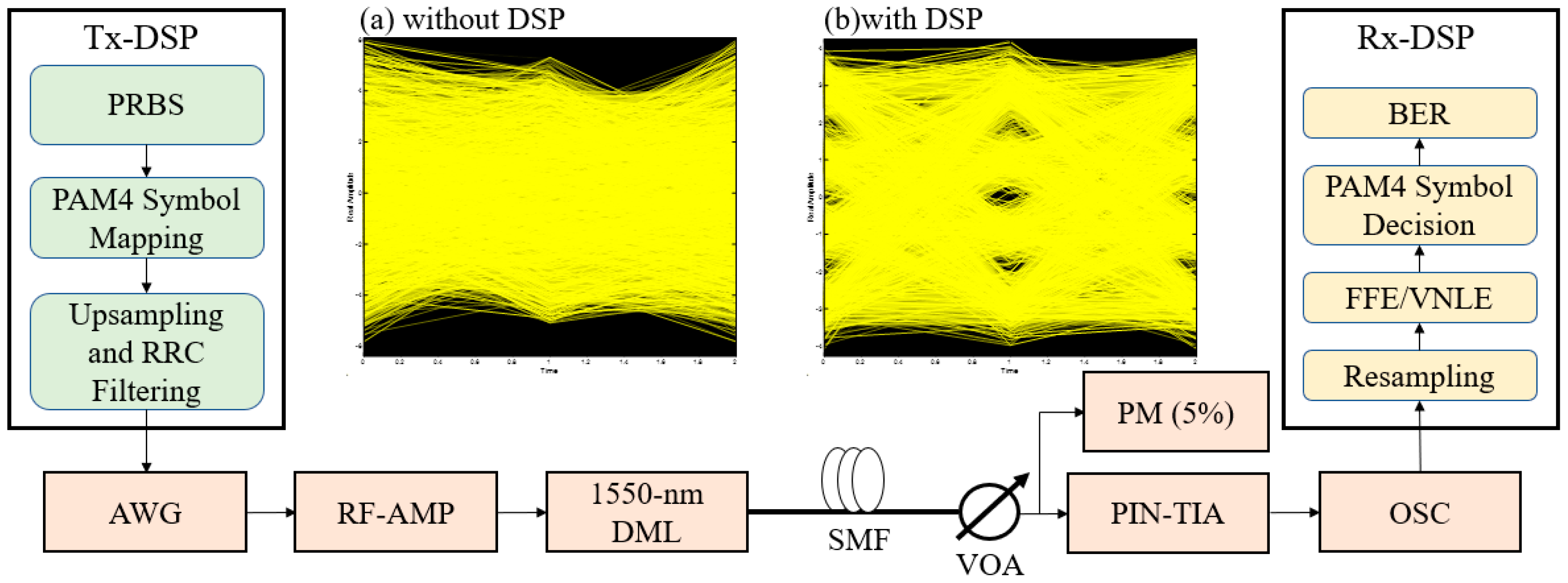
3. Experimental Setup
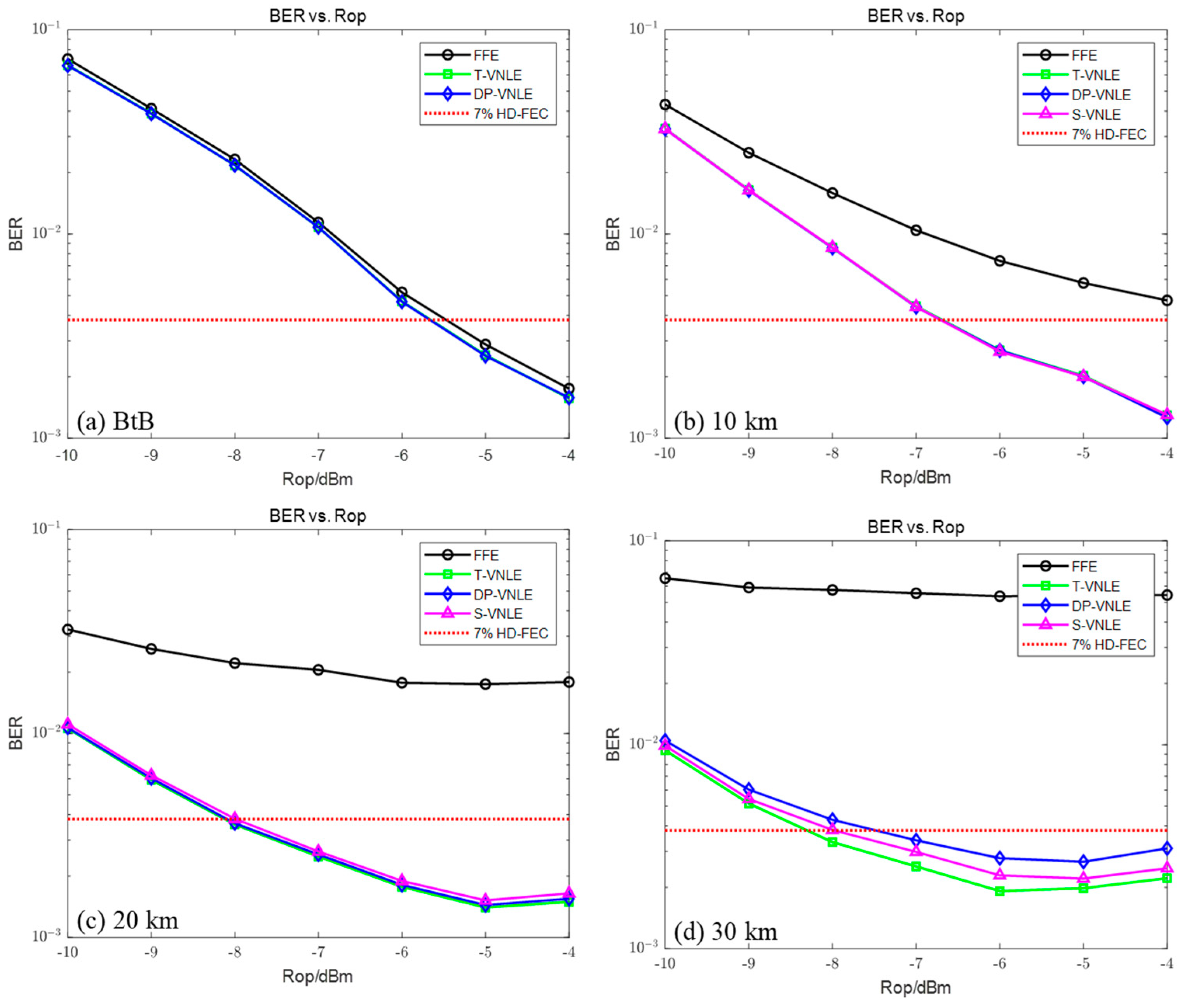
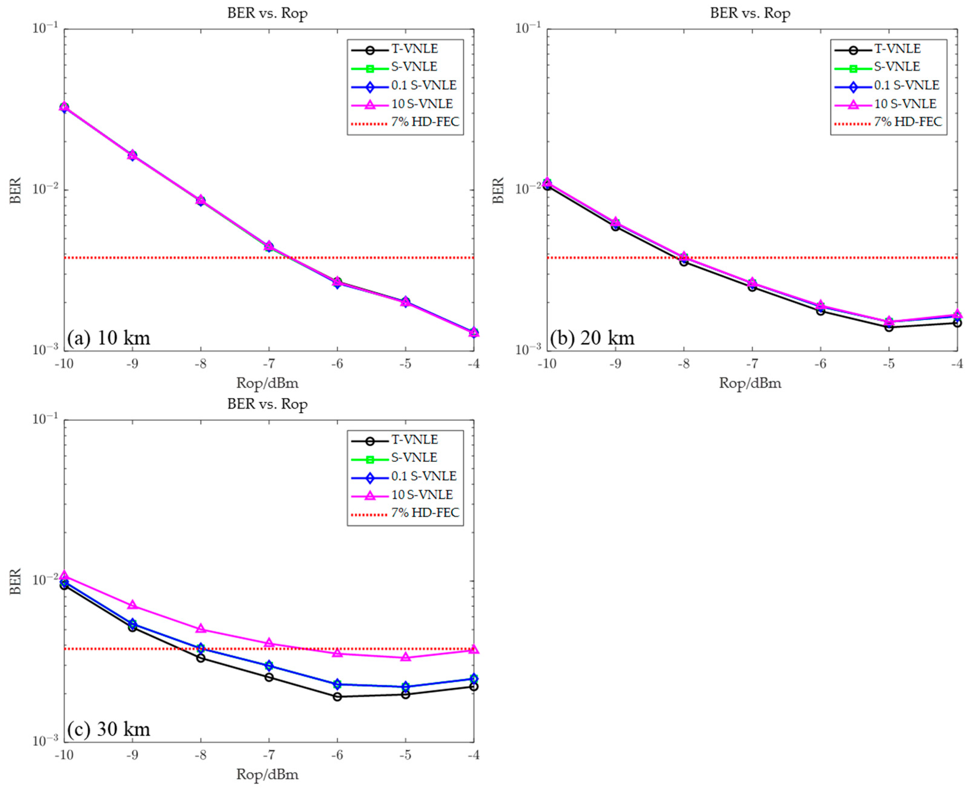
In this paper, 54 Gbit/s PAM-4 signal transmissions are realized over a 30 km SMF in the C-band (1550-nm) using a 10 G class DML, which has a 3 dB bandwidth of around 15 GHz.
The experimental setup for the IM/DD systems is illustrated in Figure 1, in which the PAM signals are generated in MATLAB by using the pseudo-random bit sequences (PRBS) and encoded using gray-coding with the help of the transmitter side offline DSP block. The generated PAM-4 symbols are up-sampled to apply the root-raised cosine (RRC) pulse shaping with a roll-off factor of 0.1 to realize Nyquist pulse shaping and to match the fundamental clock frequency of the arbitrary waveform generator (Keysight M9502A) of 62 GSa/s.
The analog bandwidth of the Keysight ArbWG is 32 GHz, and the peak-to-peak voltage (Vpp) of the ArbWG outputs is optimized at 75 mV. In the experiment, we amplify the output of the ArbWG by using a 16 dB gain RF amplifier with a bandwidth of 25 GHz. Next, the amplified RF signals are used to drive a commercial 1550 nm DML.
After the optical signal from the DML is transmitted through different lengths of optical fiber, the PAM-modulated optical signals are detected by using a 40 GHz photodetector with the responsivity of 0.6 A/W at 1550 nm for optical-to-electrical conversion. However, the photodetector is used to receive OOK signals, so the signal performance of the PAM4 signals will be degraded due to nonlinearity at high power. To measure the sensitivity of the receiver, a VOA is placed before the photodetector for adjusting the received optical power (ROP). Next, the 36 Ghz bandwidth real-time oscilloscope (RTO) operating at 80 GSa/s (The LabMaster 10 Zi-A) captures the received signal. To synchronize the reference clock between the ArbWG and the RTO, the 10 MHz output reference clock of the RTO is used as the reference clock for the ArbWG. Afterward, the captured signal is sent to the receiver side offline DSP block for signal processing.
In the Rx-DSP block, after matched filtering, we resample the PAM-4 signals. Next, the digital PAM-4 signals are sent to the linear/nonlinear equalizers. By using the training sequence of the FFE/VNLE, the tap weight adaptive process is realized, and the equalizer is placed to compensate the linear and nonlinear distortion of the DML. After signal demodulation, the BER is calculated in MATLAB to investigate the performance of the transmission system.

4. Results

We first find the best filter tap number. The results are shown in Figure 2. The length L1 of the linear memory is first determined by running only the linear part of the T-VNLE (i.e., linear FFE). It shows that the bit error rate decreases with the increase in L1, but after L1 = 11, the bit error rate decreases slowly and gradually does not decline. Therefore, we determine that the linear part tap L1 is 15. Then, we measured the BER curve of the traditional second-order VNLE as a function of the memory length L2 with L1 fixed to 15. The performance of nonlinear equalizer improves with the increase in the number of taps, but tends to be stable when it is greater than 13. Although the bit error rate will decline, it has slowed. Therefore, we set the second-order nonlinear partial tap L2 to 13.
Next, we study the performance of the proposed equalizer. Figure 3 shows the BER performance at different transmission distances.
It can be seen that in the back-to-back performance shown in Figure 3a, the performances of all equalizers are similar. The performance of the linear equalizer FFE is only slightly worse than that of the nonlinear equalizer, and the lower error rate limit is not observed. This is because the system performance is mainly limited by linear damage (including the uneven frequency response of devices), and the number of taps of the nonlinear equalizer is more than that of the linear equalizer FFE, so its performance will be slightly better.
In the transmission results of (b) 10 km, (c) 20 km, and (d) 30 km, the FFE algorithm of the linear equalizer always shows the worst performance, and cannot reach 3.8 × 10⁻³ forward error correction (FEC) threshold after 10 km.
It should be noted that the performance of the system after transmission is mainly limited by the waveform distortion caused by the interaction between the adiabatic chirp of the DML and the fiber dispersion. The second-order Volterra series can effectively simulate this nonlinear distortion, so the second-order VNLES can significantly improve the bit error rate. After the transmission of (b) 10 km and (c) 20 km, it can be seen that the performance of different VNLE algorithms is not significantly different because the transmission distance is relatively short at this time and the influence of second-order nonlinearity is small. However, after 30 km transmission, it is obvious that the T-VNLE is the best for signal recovery, but its second-order complexity is as high as 91; for the DP-VNLE, although its complexity is reduced, and the second-order complexity is 46, its performance will also decline significantly, and the difference in reception sensitivity is close to 1 dB; although the performance of the proposed S-VNLE has decreased, it is still better than the DP-VNLE, and the reception sensitivity has decreased by no more than 0.2 dB. The computational complexity of the second-order term in its algorithm is only 46, which is the same as that of the DP-VNLE. Compared with the T-VNLE, it has 49.5% of its computational complexity of the second-order term. The calculation complexity of the second-order terms of the three algorithms at different distances is shown in Figure 4.
Finally, we discuss the related problems of the zeroing threshold. Firstly, set different reset thresholds, set the average value of the calculated coefficients as the default threshold, and also set values greater than and less than the default threshold. For example, set a 10-times average value and a 1/10 average value as the reset threshold, but they are all related to link parameters. Different S-VNLE structures will be obtained. The summary of the second-order tap numbers of different VNLE structures is shown in Table 1. It can be seen that when the zeroing threshold is set to an average value or a smaller 1/10 average value, the structure of the S-VNLE changes little, while when the zeroing threshold is set to a 10-times larger average value, its structure changes with the increase in distance. We believe that this is because with the increase in distance, the degree of dispersion between the second-order coefficients will gradually become smaller, so when the distance becomes longer, the larger zeroing threshold will cause more coefficients to be filtered out, and the corresponding S-VNLE structure will also change greatly. The corresponding BER curve is shown in Figure 5. It can be seen from the results that when the distance is short, different zeroing threshold settings have little impact on the S-VNLE structure. With the increase in the distance, different zeroing threshold settings will lead to different S-VNLE structures. From the bit error rate curve, setting the zeroing threshold as the average value can always achieve the best results. After increasing the zeroing threshold, although the computational complexity will be greatly reduced, the performance will also be degraded. This is because too many coefficient terms are removed, resulting in the S-VNLE equalizer structure not applicable to the current system.

5. Discussion

Nonlinear equalizers are undoubtedly necessary and very effective for DML-based direct modulation detection systems, but different nonlinear equalizers usually bring different effects and costs. Specifically, the VNLE is very effective in recovering signals from DML/DD systems, but, from the derivation above, it can be seen that some coefficient terms are small and can be deleted. Therefore, we have attempted this work and achieved some results. Compared with our proposed S-VNLE and T-VNLE, when the transmission distance is 30 km, the reception sensitivity only decreases by no more than 0.2 dB, but the complexity decreases by more than 50%. The DP-VNLE performs the same or even slightly better than the S-VNLE at short transmission distances, but the reason for its poor performance at longer transmission distances is that in many engineering practices, the coefficients of the VNLE typically exhibit aggregation, with the effective term mainly concentrated in the square term and the coefficients far from the square term being smaller. This is generally the case in DML/DD systems, but there may be some differences. Through our derivation, we found that when the distance is short, this aggregation is more obvious, so the structure of the DP-VNLE exactly matches it. However, the proposed scheme generates interference due to some coefficient terms that are farther from the signal’s own symbol. Therefore, the DP-VNLE has the same or even slightly better performance than the S-VNLE at short transmission distances. When the transmission distance is long, this clustering is no longer obvious, so the structural advantage of the S-VNLE is more obvious, and the signal recovery effect is also better.
In order to balance the performance and the cost of the S-VNLE, different thresholds were attempted to verify the impact of more or less coefficient terms on performance under the proposed simplification approach. When the threshold was raised, more coefficient terms were removed, resulting in a significant decrease in performance. This is because the coefficient terms that contribute to the signal were also removed. When the threshold was lowered, more coefficient terms were retained, but their contribution to the signal was small; therefore, the performance hardly changed. Taking into account the performance and the cost of communication systems, it is reasonable and effective to use the average coefficient as a threshold.

6. Conclusions

We have proposed and demonstrated second-order Volterra nonlinear equalizers specifically designed for DML/DD systems.
The second-order Volterra series expression for the DML/DD system shows that the adiabatic chirp of the DML when combined with fiber chromatic dispersion produces the second-order beating terms between the signal and the time integral of the signal. Since the time integral of the signal can be expressed as a sum of sampled signals, the second-order nonlinear distortions generated by the adiabatic chirp make the coefficients of some cross terms regularly smaller. We reset those cross-beating terms to zero and simplify the second-order Volterra equalizer. The proposed equalizer has a similar implementation complexity to the DP-VNLE, and has better performance.
The performance of the proposed equalizer is evaluated using a 56 Gb/s PAM-4 signal generated from a 1.55 μm DML. The results show that the proposed equalizer outperforms the DP-VNLE. For example, we achieve the sensitivity improvement of 0.5 dB in 30 km transmission experiment when we replace the DP-VNLE with the proposed equalizer. Thus, we believe that the proposed equalizer could be used to lower the implementation cost of DML/DD systems.

Author Contributions

Conceptualization, Z.F. and W.L.; methodology, Z.F.; software, Z.F.; validation, Z.F. and W.L.; formal analysis, Z.F.; investigation, Z.F.; resources, W.L.; data curation, Z.F.; writing—original draft preparation, Z.F.; writing—review and editing, Z.F.; visualization, Z.F.; supervision, W.L.; project administration, W.L., N.L., P.H., M.L., Q.H., L.H. and Y.J.; funding acquisition, W.L. All authors have read and agreed to the published version of the manuscript.

Funding

This research received no external funding.

Institutional Review Board Statement

Not applicable.

Informed Consent Statement

Not applicable.

Data Availability Statement

The data presented in this study are available on request from the corresponding author.

Acknowledgments

I would like to thank Na Li for her support of the experiment and data processing.

Conflicts of Interest

The authors declare no conflict of interest.

References

  1. Xin, H.; Zhang, K.; Li, L.; He, H.; Hu, W. 50 Gbps PAM-4 Over Up to 80-km Transmission With C-Band DML Enabled by Post-Equalizer. IEEE Photon-Technol. Lett. 2020, 32, 643–646. [Google Scholar] [CrossRef]
  2. Fu, Y.; Kong, D.; Bi, M.; Xin, H.; Jia, S.; Zhang, K.; Hu, W.; Hu, H. Computationally efficient 104 Gb/s PWL-Volterra equalized 2D-TCM-PAM8 in dispersion unmanaged DML-DD system. Opt. Express 2020, 28, 7070–7079. [Google Scholar] [CrossRef] [PubMed]
  3. Fu, Y.; Kong, D.; Xin, H.; Jia, S.; Zhang, K.; Bi, M.; Hu, W.; Hu, H. Piecewise Linear Equalizer for DML Based PAM-4 Signal Transmission Over a Dispersion Uncompensated Link. J. Light. Technol. 2019, 38, 654–660. [Google Scholar] [CrossRef]
  4. Plant, D.V.; Morsy-Osman, M.; Chagnon, M. Optical Communication Systems for Datacenter Networks. In Optical Fiber Communication Conference; OSA Technical Digest (online); Optica Publishing Group: Washington, DC, USA, 2017; p. W3B.1. [Google Scholar]
  5. Chang, F.; Bhoja, S. New Paradigm Shift to PAM4 Signalling at 100/400G for Cloud Data Centers: A Performance Review. In Proceedings of the 2017 European Conference on Optical Communication (ECOC), Gothenburg, Sweden, 17–21 September 2017; pp. 1–3. [Google Scholar] [CrossRef]
  6. Zhang, K.; Zhuge, Q.; Xin, H.; Hu, W.; Plant, D.V. Performance comparison of DML, EML and MZM in dispersion-unmanaged short reach transmissions with digital signal processing. Opt. Express 2018, 26, 34288–34304. [Google Scholar] [CrossRef] [PubMed]
  7. He, P.; Sun, M.; Li, W.; Li, N.; Feng, Z.; Zhang, H.; Yao, C.; Sun, L.; He, Z.; Zhu, H.; et al. Demonstration of 112Gb/s PAM-4/6 Transmission Using Low-Complexity Volterra-DFE. In Proceedings of the 2022 Asia Communications and Photonics Conference (ACP), presented at Asia Communications and Photonics Conference, Shenzhen, China, 5–8 November 2022; pp. 919–923, ACP2022. [Google Scholar]
  8. Gao, F.; Zhou, S.; Li, X.; Fu, S.; Deng, L.; Tang, M.; Liu, D.; Yang, Q. 2 × 64 Gb/s PAM-4 transmission over 70 km SSMF using O-band 18G-class directly modulated lasers (DMLs). Opt. Express 2017, 25, 7230–7237. [Google Scholar] [CrossRef] [PubMed]
  9. Zhang, K.; Zhuge, Q.; Xin, H.; Xing, Z.; Xiang, M.; Fan, S.; Yi, L.; Hu, W.; Plant, D.V. Demonstration of 50Gb/s/λ Symmetric PAM4 TDM-PON with 10G-Class Optics and DSP-Free ONUs in the O-Band; Optical Fiber Communications Conference and Exposition (OFC): San Diego, CA, USA, 2018; pp. 1–3. [Google Scholar]
  10. Gao, Y.; Cartledge, J.C.; Yam, S.S.; Rezania, A.; Matsui, Y. 112 Gb/s PAM-4 Using a Directly Modulated Laser with Linear Pre-Compensation and Nonlinear Post-Compensation. In Proceedings of the ECOC 2016 42nd European Conference on Optical Communication, Dusseldorf, Germany, 18–22 September 2016; pp. 1–3. [Google Scholar]
  11. Bergmann, E.; Kuo, C.; Huang, S. Dispersion-induced composite second-order distortion at 1.5 mu m. IEEE Photon-Technol. Lett. 1991, 3, 59–61. [Google Scholar] [CrossRef] [PubMed]
  12. Kim, B.G.; Bae, S.H.; Kim, H.; Chung, Y.C. DSP-based CSO cancellation technique for RoF transmission system im-plemented by using directly modulated laser. Opt. Express 2017, 25, 12152–12160. [Google Scholar] [CrossRef] [PubMed]
  13. Wei, C.-C.; Cheng, H.-L.; Huang, W.-X. On Adiabatic Chirp and Compensation for Nonlinear Distortion in DML-Based OFDM Transmission. J. Light. Technol. 2018, 36, 3502–3513. [Google Scholar] [CrossRef]
  14. Yan, W.; Liu, B.; Li, L.; Tao, Z.; Takahara, T.; Rasmussen, J.C. Nonlinear Distortion and DSP-based Compensation in Metro and Access Networks using Discrete Multi-tone. In European Conference and Exhibition on Optical Communication; OSA Technical Digest (online); Optica Publishing Group: Washington, DC, USA, 2012. [Google Scholar]
  15. Stojanovic, N.; Karinou, F.; Qiang, Z.; Prodaniuc, C. Volterra and Wiener Equalizers for Short-Reach 100G PAM-4 Applications. J. Light. Technol. 2017, 35, 4583–4594. [Google Scholar] [CrossRef]
  16. Xia, C.; Rosenkranz, W. Nonlinear Electrical Equalization for Different Modulation Formats With Optical Filtering. J. Light. Technol. 2007, 25, 996–1001. [Google Scholar] [CrossRef]
  17. Yu, Y.; Choi, M.R.; Bo, T.; He, Z.; Che, Y.; Kim, H. Low-Complexity Second-Order Volterra Equalizer for DML-Based IM/DD Transmission System. J. Light. Technol. 2019, 38, 1735–1746. [Google Scholar] [CrossRef]
  18. Reza, A.G.; Rhee, J.-K.K. Blind nonlinearity mitigation of 10G DMLs using sparse Volterra equalizer in IM/DD PAM-4 transmission systems. Opt. Fiber Technol. 2020, 59, 102322. [Google Scholar] [CrossRef]
  19. Diamantopoulos, N.-P.; Nishi, H.; Kobayashi, W.; Takeda, K.; Kakitsuka, T.; Matsuo, S. On the Complexity Reduction of the Second-Order Volterra Nonlinear Equalizer for IM/DD Systems. J. Light. Technol. 2018, 37, 1214–1224. [Google Scholar] [CrossRef]
  20. Chen, Y.; Wang, Y.; Li, W.; Mei, M.; Feng, Z.; Wu, C.; Sun, L.; Zhu, H.; Zhao, X. 106 Gbit/s PAM4 Transmission Employing a 15 GHz Directly Modulated Laser. In Proceedings of the 2021 Asia Communications and Photonics Conference (ACP), Shanghai, China, 24–27 October 2021. [Google Scholar]
  21. Yu, Y.; Choi, M.R.; Bo, T.; Che, Y.; Kim, D.; Kim, H. Nonlinear Equalizer Based on Absolute Operation for IM/DD System Using DML. IEEE Photon- Technol. Lett. 2020, 32, 426–429. [Google Scholar] [CrossRef]
  22. Batista, E.; Seara, R. On the performance of adaptive pruned Volterra filters. Signal Process. 2013, 93, 1909–1920. [Google Scholar] [CrossRef]
  23. Savory, S.J. Digital filters for coherent optical receivers. Opt. Express 2008, 16, 804–817. [Google Scholar] [CrossRef] [PubMed]
  24. Xu, T.; Jacobsen, G.; Popov, S.; Li, J.; Vanin, E.; Wang, K.; Friberg, A.T.; Zhang, Y. Chromatic dispersion compensation in coherent transmission system using digital filters. Opt. Express 2010, 18, 16243–16257. [Google Scholar] [CrossRef] [PubMed]
  25. Raz, G.; van Veen, B. Baseband Volterra filters for implementing carrier based nonlinearities. IEEE Trans. Signal Process. 1998, 46, 103–114. [Google Scholar] [CrossRef]
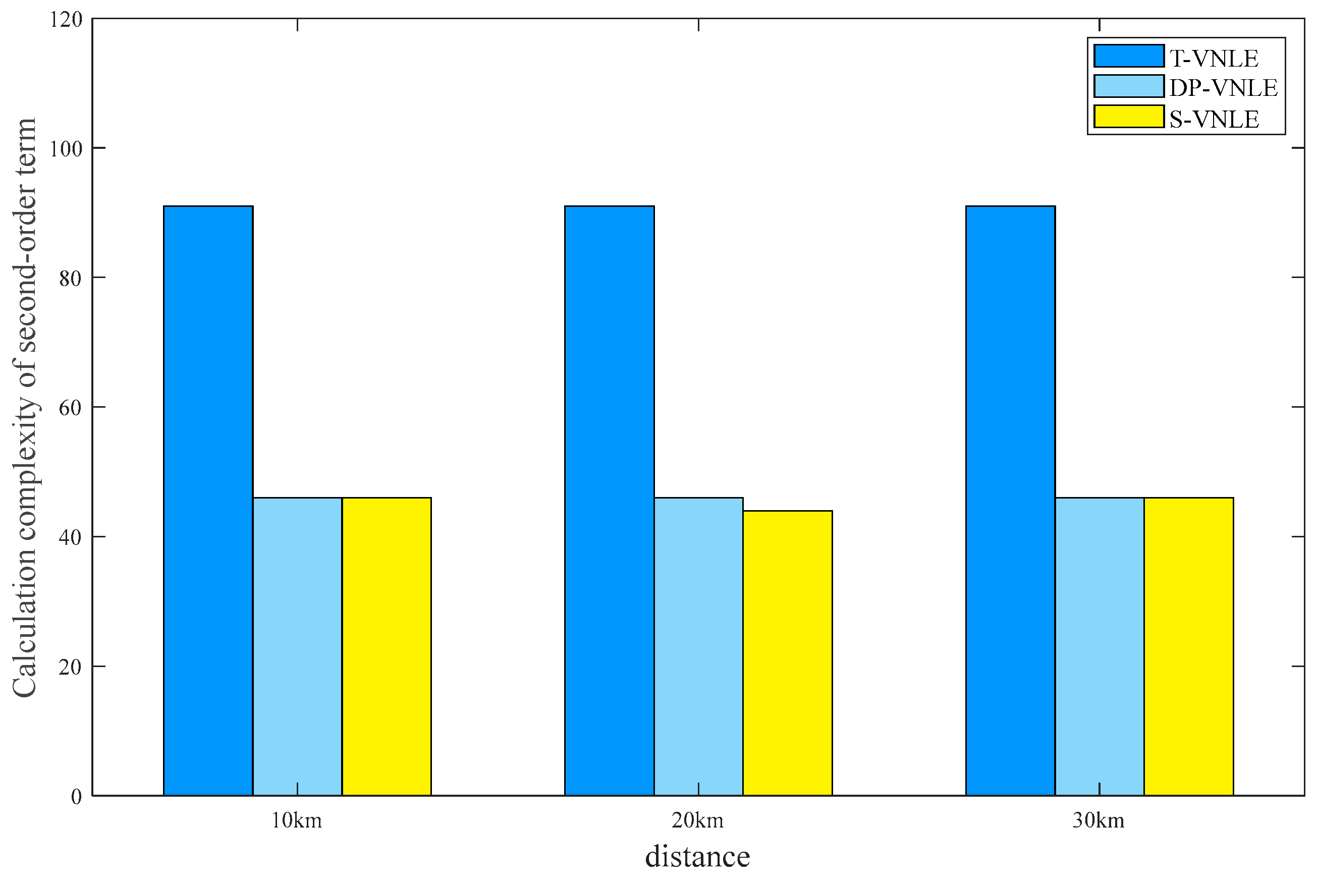
Figure 1. Experimental setup. Eye diagrams after 30 km. SMF transmission; (a) without DSP and (b) with DSP.
Photonics 10 01174 g001
Figure 2. BER performance versus the memory length of linear equalizer, L1, and nonlinear equalizer, L2.
Photonics 10 01174 g002
Figure 3. Measured BER curves after (a) 0, (b) 10, (c) 20, and (d) 30 km transmissions.
Photonics 10 01174 g003
Figure 4. Second-order calculation complexity of three algorithms at different distances.
Photonics 10 01174 g004
Figure 5. BER curves of different algorithms after (a) 10, (b) 20, and (c) 30 km transmissions.
Photonics 10 01174 g005
Table 1. Number of second-order terms of different algorithms.
DistanceT-VNLES-VNLE0.1S-VNLE10S-VNLE
10 km91464358
20 km9144 4443
30 km9146 4635
Disclaimer/Publisher’s Note: The statements, opinions and data contained in all publications are solely those of the individual author(s) and contributor(s) and not of MDPI and/or the editor(s). MDPI and/or the editor(s) disclaim responsibility for any injury to people or property resulting from any ideas, methods, instructions or products referred to in the content.

