Reducing the Crosstalk in Collinear Holographic Data Storage Systems Based on Random Position Orthogonal Phase-Coding Reference

 ,
, 
Abstract
:1. Introduction
2. Configurations and Methods
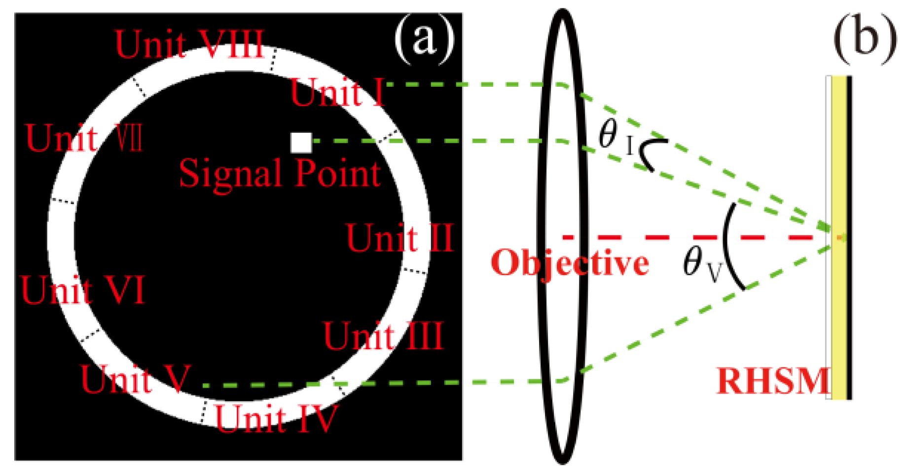
2.1. Configurations
2.2. Methods
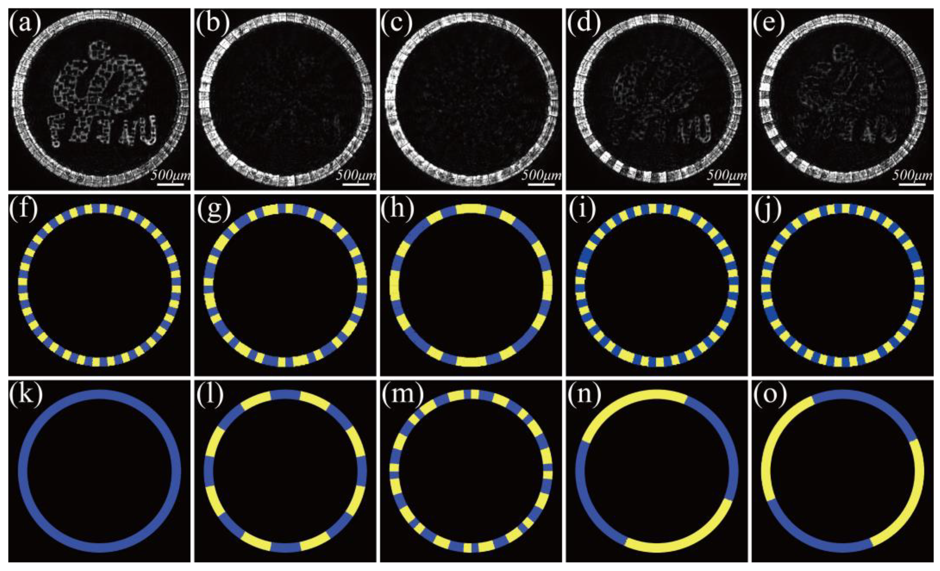
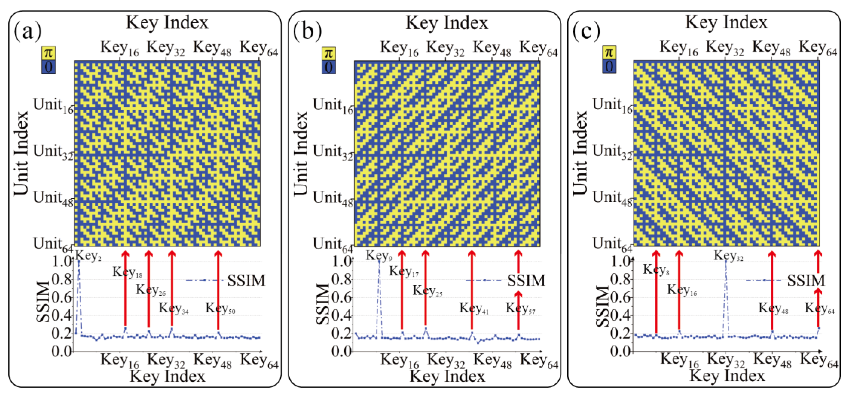
3. Results
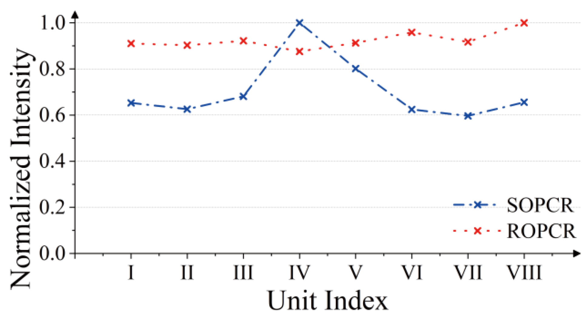
3.1. Crosstalk in Orthogonal Phase-Coding Multiplexing CHDSS with SOPCR
3.2. Use ROPCR to Suppress Crosstalk
4. Discussion
5. Conclusions
Author Contributions
Funding
Institutional Review Board Statement
Informed Consent Statement
Data Availability Statement
Acknowledgments
Conflicts of Interest
References
- Church, G.M.; Gao, Y.; Kosuri, S. Next-Generation Digital Information Storage in DNA. Science 2012, 337, 1628. [Google Scholar] [CrossRef] [PubMed]
- Grass, R.N.; Heckel, R.; Puddu, M.; Paunescu, D.; Stark, W.J. Robust Chemical Preservation of Digital Information on DNA in Silica with Error-Correcting Codes. Angew. Chem. Int. Ed. 2015, 54, 2552–2555. [Google Scholar] [CrossRef]
- Zhang, J.; Gecevičius, M.; Beresna, M.; Kazansky, P.G. Seemingly Unlimited Lifetime Data Storage in Nanostructured Glass. Phys. Rev. Lett. 2014, 112, 033901. [Google Scholar] [CrossRef] [PubMed]
- Wang, H.; Lei, Y.; Wang, L.; Sakakura, M.; Yu, Y.; Shayeganrad, G.; Kazansky, P.G. 100-Layer Error-Free 5D Optical Data Storage by Ultrafast Laser Nanostructuring in Glass. Laser Photonics Rev. 2022, 16, 2100563. [Google Scholar] [CrossRef]
- Heanue, J.F.; Bashaw, M.C.; Hesselink, L. Encrypted holographic data storage based on orthogonal-phase-code multiplexing. Appl. Opt. 1995, 34, 6012–6015. [Google Scholar] [CrossRef] [PubMed]
- van Heerden, P.J. Theory of Optical Information Storage in Solids. Appl. Opt. 1963, 2, 393–400. [Google Scholar] [CrossRef]
- Hao, J.; Lin, X.; Lin, Y.; Chen, M.; Chen, R.; Situ, G.; Horimai, H.; Tan, X. Lensless complex amplitude demodulation based on deep learning in holographic data storage. Opto-Electron. Adv. 2023, 6, 220157. [Google Scholar] [CrossRef]
- Bashaw, M.C.; Heanue, J.F.; Aharoni, A.; Walkup, J.F.; Hesselink, L. Cross-talk considerations for angular and phase-encoded multiplexing in volume holography. J. Opt. Soc. Am. B 1994, 11, 1820–1836. [Google Scholar] [CrossRef]
- Koppa, P. Phase-to-amplitude data page conversion for holographic storage and optical encryption. Appl. Opt. 2007, 46, 3561–3571. [Google Scholar] [CrossRef]
- Matoba, O.; Javidi, B. Encrypted optical storage with wavelength-key and random phase codes. Appl. Opt. 1999, 38, 6785–6790. [Google Scholar] [CrossRef]
- Tan, X.; Matoba, O.; Shimura, T.; Kuroda, K. Improvement in holographic storage capacity by use of double-random phase encryption. Appl. Opt. 2001, 40, 4721–4727. [Google Scholar] [CrossRef] [PubMed]
- Nobukawa, T.; Barada, D.; Nomura, T.; Fukuda, T. Orthogonal polarization encoding for reduction of interpixel cross talk in holographic data storage. Opt. Express 2017, 25, 22425–22439. [Google Scholar] [CrossRef] [PubMed]
- Zhu, L.; Cao, Y.; Chen, Q.; Ouyang, X.; Xu, Y.; Hu, Z.; Qiu, J.; Li, X. Near-perfect fidelity polarization-encoded multilayer optical data storage based on aligned gold nanorods. Opto-Electron. Adv. 2021, 4, 210002. [Google Scholar] [CrossRef]
- Denz, C.; Pauliat, G.; Roosen, G.; Tschudi, T. Volume hologram multiplexing using a deterministic phase encoding method. Opt. Commun. 1991, 85, 171–176. [Google Scholar] [CrossRef]
- Denz, C.; Pauliat, G.; Roosen, G.; Tschudi, T. Potentialities and limitations of hologram multiplexing by using the phase-encoding technique. Appl. Opt. 1992, 31, 5700–5705. [Google Scholar] [CrossRef] [PubMed]
- Kim, Y.; Sim, M.; Moon, I. Secure storage and retrieval schemes for multiple encrypted digital holograms with orthogonal phase encoding multiplexing. Opt. Express 2019, 27, 22147–22160. [Google Scholar] [CrossRef] [PubMed]
- Liu, J.P.; Horimai, H.; Lin, X.; Huang, Y.; Tan, X. Phase modulated high density collinear holographic data storage system with phase-retrieval reference beam locking and orthogonal reference encoding. Opt. Express 2018, 26, 3828. [Google Scholar] [CrossRef]
- Situ, G.H.; Zhang, J.J. Double random-phase encoding in the Fresnel domain. Opt. Lett. 2004, 29, 1584–1586. [Google Scholar] [CrossRef]
- Liao, M.; Zheng, S.; Pan, S.; Lu, D.; He, W.; Situ, G.; Peng, X. Deep-learning-based ciphertext-only attack on optical double random phase encryption. Opto-Electron. Adv. 2021, 4, 200016. [Google Scholar] [CrossRef]
- Zhou, K.; Fan, J.; Fan, H.; Li, M. Secure image encryption scheme using double random-phase encoding and compressed sensing. Opt. Laser Technol. 2020, 121, 105769. [Google Scholar] [CrossRef]
- Liansheng, S.; Cong, D.; Xiao, Z.; Ailing, T.; Anand, A. Double-image encryption based on interference and logistic map under the framework of double random phase encoding. Opt. Lasers Eng. 2019, 122, 113–122. [Google Scholar] [CrossRef]
- Lin, X.; Huang, Y.; Cheng, Y.; Liu, J.; Xu, K.; Li, X.; Tan, X. Inter-page-crosstalk reduction in holographic data storage system through phase modulation in signal region. Jpn. J. Appl. Phys. 2016, 55, 09SA07. [Google Scholar] [CrossRef]
- Chuang, C.-H.; Chen, C.-Y.; Chang, H.-T.; Lin, H.-Y.; Kuo, C.-F. Reducing Defocused-Information Crosstalk to Multi-View Holography by Using Multichannel Encryption of Random Phase Distribution. Appl. Sci. 2022, 12, 1413. [Google Scholar] [CrossRef]
- Makey, G.; Yavuz, Ö.; Kesim, D.K.; Turnalı, A.; Elahi, P.; Ilday, S.; Tokel, O.; Ilday, F.Ö. Breaking crosstalk limits to dynamic holography using orthogonality of high-dimensional random vectors. Nat. Photonics 2019, 13, 251–256. [Google Scholar] [CrossRef]
- Tokoro, M.; Fujimura, R. Single-shot detection of four-level phase modulated signals using inter-pixel crosstalk for holographic data storage. Jpn. J. Appl. Phys. 2021, 60, 022004. [Google Scholar] [CrossRef]
- Mignani, A.G.; Berghmans, F.; Orlov, V.; Shubenkova, E.; Matital, R.P.; Gavril’eva, K.; Fedorov, E.; Gorelaya, A.; Venediktov, V.Y. Approaches to cross-talk noise reduction in modal holographic wavefront sensors. In Proceedings of the Optical Sensing and Detection V, Strasbourg, France, 23–26 April 2018. [Google Scholar]
- Cao, L.C.; Liu, J.Q.; Li, J.H.; He, Q.S.; Jin, G.F. Orthogonal reference pattern multiplexing for collinear holographic data storage. Appl. Opt. 2014, 53, 1–8. [Google Scholar] [CrossRef]
- Li, J.; Cao, L.; Tan, X.; He, Q.; Jin, G. Transmission Type of Collinear Volume Holographic Storage Technology Based on LiNbO3Crystal. Acta. Opt. Sin. 2012, 32, 0409001. [Google Scholar] [CrossRef]
- Pang, Y.; Cao, A.; Wang, J.; Pang, H.; Deng, Q. Simple encoding method of phase-only hologram for low crosstalk full-color multi-plane holographic projection. Opt. Lasers Eng. 2021, 147, 106748. [Google Scholar] [CrossRef]
- Horimai, H.; Tan, X.; Li, J. Collinear holography. Appl. Opt. 2005, 44, 2575–2579. [Google Scholar] [CrossRef]
- Horimai, H.; Tan, X. Advanced Collinear Holography. Opt. Rev. 2005, 12, 90–92. [Google Scholar] [CrossRef]
- Lin, X.; Liu, J.P.; Hao, J.Y.; Wang, K.; Zhang, Y.Y.; Li, H.; Horimai, H.; Tan, X.D. Collinear holographic data storage technologies. Opto-Electron. Adv. 2020, 3, 190004. [Google Scholar] [CrossRef]
- Taketomi, Y.; Ford, J.E.; Sasaki, H.; Ma, J.; Fainman, Y.; Lee, S.H. Incremental recording for photorefractive hologram multiplexing. Opt. Lett. 1991, 16, 1774–1776. [Google Scholar] [CrossRef] [PubMed]
- Horadam, K.J. Hadamard matrices and their applications: Progress 2007–2010. Cryptogr. Commun. 2010, 2, 129–154. [Google Scholar] [CrossRef]
- Chawla, N.V.; Bowyer, K.W.; Hall, L.O.; Kegelmeyer, W.P. SMOTE: Synthetic Minority Over-sampling Technique. J. Artif. Intell. Res. 2002, 16, 321–357. [Google Scholar] [CrossRef]
- Liu, Y.; Fan, F.L.; Tan, X.D. SiO2 NPs-PQ/PMMA Photopolymer Material Doped with a High-Concentration Photosensitizer for Holographic Storage. Polymers 2020, 12, 816. [Google Scholar] [CrossRef] [PubMed]
- Kogelnik, H. Coupled Wave Theory for Thick Hologram Gratings. Bell Syst. Tech. J. 1969, 48, 2909–2947. [Google Scholar] [CrossRef]
- Kim, H.; Lee, Y.H. Cross talk between holograms of finite contrast in a phase-code multiplexing system. Opt. Lett. 2004, 29, 113–115. [Google Scholar] [CrossRef]


Disclaimer/Publisher’s Note: The statements, opinions and data contained in all publications are solely those of the individual author(s) and contributor(s) and not of MDPI and/or the editor(s). MDPI and/or the editor(s) disclaim responsibility for any injury to people or property resulting from any ideas, methods, instructions or products referred to in the content. |
© 2023 by the authors. Licensee MDPI, Basel, Switzerland. This article is an open access article distributed under the terms and conditions of the Creative Commons Attribution (CC BY) license (https://creativecommons.org/licenses/by/4.0/).
Share and Cite
Song, H.; Li, J.; Lin, D.; Liu, H.; Lin, Y.; Hao, J.; Wang, K.; Lin, X.; Tan, X. Reducing the Crosstalk in Collinear Holographic Data Storage Systems Based on Random Position Orthogonal Phase-Coding Reference. Photonics 2023, 10, 1160. https://doi.org/10.3390/photonics10101160
Song H, Li J, Lin D, Liu H, Lin Y, Hao J, Wang K, Lin X, Tan X. Reducing the Crosstalk in Collinear Holographic Data Storage Systems Based on Random Position Orthogonal Phase-Coding Reference. Photonics. 2023; 10(10):1160. https://doi.org/10.3390/photonics10101160
Chicago/Turabian StyleSong, Haiyang, Jianan Li, Dakui Lin, Hongjie Liu, Yongkun Lin, Jianying Hao, Kun Wang, Xiao Lin, and Xiaodi Tan. 2023. "Reducing the Crosstalk in Collinear Holographic Data Storage Systems Based on Random Position Orthogonal Phase-Coding Reference" Photonics 10, no. 10: 1160. https://doi.org/10.3390/photonics10101160
APA StyleSong, H., Li, J., Lin, D., Liu, H., Lin, Y., Hao, J., Wang, K., Lin, X., & Tan, X. (2023). Reducing the Crosstalk in Collinear Holographic Data Storage Systems Based on Random Position Orthogonal Phase-Coding Reference. Photonics, 10(10), 1160. https://doi.org/10.3390/photonics10101160