Abstract
As a function of a circular polarization beam splitter (CPBS), combining a linear polarization beam splitter with a quarter-wave plate results in a polarization error in a circular polarization fiber-optic circuit. To relieve the error, chiral dual-core photonic crystal fiber (DC-PCF) is investigated as a kind of an efficient circular polarization beam splitter by using the chiral plane-wave expansion (PWE) method. On the basis of the competitive effect in polarization and coupling length between the circular asymmetry of the structure and the chirality of the medium, the effects of the structure and the chirality are analyzed. The numerical results demonstrate that a CPBS needs the weak circular asymmetry in its structure and a relatively stronger chirality of the medium. Then, a kind of CPBS based on chiral DC-PCF is designed with weaker chirality, with a central wavelength of 1.55 μm. The simulation shows the superior performance of having a shorter coupling length and a higher extinction ratio. Furthermore, the dual-wavelength of 1.55 μm and 1.30 μm with left-circular polarization can further be separated by the corresponding chiral DC-PCF. The results show promising applications for the circular polarized multiplexer/demultiplexer in fiber laser communication systems.
1. Introduction
Dual-core photonic crystal fiber (DC-PCF), as a kind of beam splitter that can split beams with different polarizations or wavelengths, has gradually attracted more and more attention thanks to the composition of its having only one material and its unusual properties, such as tailored coupling length (CL), spectral bandwidth and extinction ratio (ER) [,,,,], and it can be applied in circuits for fiber laser communication, optical integration and sensing. According to the polarization states of light, the devices can be classified into linearly polarized beam splitters (LPBSs) and circularly polarized beam splitters (CPBSs), which can respectively separate the orthogonally linearly [,,,,] and oppositely circularly polarized light []. Generally, the LPBSs can be realized by introducing orthogonal asymmetry, named circular asymmetry (geometric anisotropy or distribution of materials), into a cross section of the fiber, such as the air hole’s or core’s position [,,], size [,,,,,,], shape [,] or holes filled with some liquid or multiple materials [,,,,,,], and applied in the linearly polarized system to suppress the polarization error or noise [,]. Because of the inherent defects, such as the polarization axis’s imperfectly aligning during welding and stress caused by extrusion or stretching in practical applications, the polarization error and noise would inevitably occur [,]. Research results demonstrate that polarization error and noise can be suppressed, even eliminated, by using a circularly polarized optical fiber system [,,], since the circular birefringence can suppress the linear one in spun optical fiber for higher spun rates []. However, the polarization axis’s imperfectly aligning still remains owing to the use of all-fiber quarter-wave plates and LPBSs as all-fiber CPBSs [,,]. In fact, in the process of producing circularly polarized light, the quarter-wave plates can also introduce the error because of the imperfect interception; however, the CPBS can split the linearly polarized (LP) light to right-handed circularly polarized (RCP) and left-handed circularly polarized (LCP) ones without any additional devices or procedures because the LP light can be viewed as a combination of RCP and LCP ones. Thus, it is necessary to study all-fiber CPBSs formed by the circular polarization–maintaining fibers.
In general, the circular polarization–maintaining fibers can employ chiral structures [,,,,,] or chiral mediums [,,,,] that have axial rotation (twisted or spiral) and/or optical activity [,,,], namely structurally and dielectrically chiral fiber, where the operation wavelength is far less and much larger than the chiral object in size. The former, which has the helically twisted or spun structure, forms a kind of chiral fiber or chiral fiber grating because of the different twist angle [,,,,], which can support one or two-paired circularly polarized modes. Theoretical research results demonstrate that the twisted DC-PCF can be viewed as an all-fiber CPBS, whereas fabricated technology for undergoing symmetric distortions in twisting and drawing poses a challenge []. For the latter, theoretical studies have demonstrated that they can support the circularly polarized modes with single- and multicore [,,,,], in which a left-handed polarization beam can be leaked by single-polarization single-mode fiber that can be the manufactured as an ordinary PCF []. Recently, as a kind of CPBS, the dielectrically chiral DC-PCF can separate the oppositely circularly polarized light with stronger chirality strength []; however, its coupling length is very long. Therefore, in this paper, we will focus on the dielectrically chiral DC-PCF CPBS to optimize its structural parameters for short CL and decrease the dependence on the chirality of the medium.
In this paper, as a kind of CPBS, the dielectrically chiral DC-PCF is first considered with a shorter distance between the two cores. Given the application in practice, the operation wavelengths are selected as 1.55 μm and 1.30 μm, which are easy to be emitted by lasers, such as a quantum dot laser, a fiber laser, a superluminescent diode laser, and so on [,,,,,], and the fiber can achieve propagation with zero dispersion or near-zero dispersion for the two band [,,]. Using the chiral plane-wave expansion (PWE) method [], the effects of the circular asymmetry of the structure and the chirality of the medium are analyzed. From the competition between the circular asymmetry of structure and the chirality of the medium in polarization and CL, a shorter PCF CPBS with a weaker chirality is obtained by optimizing the geometry parameters. Then, as a kind of multiplexer/demultiplexer for circularly polarized (CP) beams is discussed, and the numerical results show that it can split beams at the dual-wavelengths of 1.55 μm and 1.30 μm that are widely used in fiber laser communication systems.
2. Model and Analysis
In order to obtain the shorter CL, having strong coupling between cores is necessary []. Hence, the chiral DC-PCF with a shorter distance between the two cores is considered, as shown in Figure 1, where the two defects (A and B) denote the dual cores; their distance is 2Λ, and Λ and d, respectively, represent the lattice constant and diameter in the air holes. The darker part is annotated as the chiral medium, and the white holes are the air ones. The tailored holes of the diameter of are, respectively, D1 and D2, which can determine the modal linearly birefringence of the fiber to tailor the CL and the corresponding polarization states.
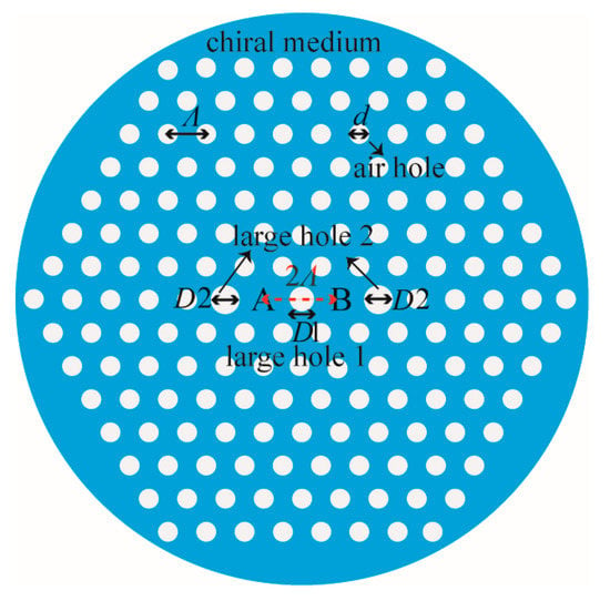
Figure 1.
The schematic diagram of a chiral DC-PCF.
Generally, the fiber has high birefringence when D1/d and D2/d are larger/less than unity; the higher the birefringence, the shorter the CLs. Additionally, when D1/d = 1 and D2/d = 1, the fiber is identical to a conventional DC-PCF, which has slight birefringence because of the asymmetry of the structure. To reduce the dependence on the chirality of the medium, the birefringence should not be too large, because of the competitive effect between the asymmetry of the structure and the chirality of the medium in polarization and CL [].
The Drude–Born–Fedorov’s constitutive relations for the chiral medium, which are employed with D = ε0εr(E + ξ∇ × E) and B = μ0μr(H + ξ∇ × H), are chosen []. ξ represents the chirality strength characterized by its specific rotatory power δ of the medium through δ = −k2n2, where k and n, respectively, denote the wavenumber in a vacuum and the average refractive index of the medium. Hence, the air can be viewed as a chiral medium with δ = 0 (achiral medium).
The coupling characteristics of a chiral DC-PCF are investigated through the chiral plane-wave expansion (PWE) method []
Because polymethyl methacrylate (PMMA) can be doped with a chiral medium or synthesized with a chiral copolymer polymer used to draw polymer PCF [,,], PMMA-doped griseofulvin is chosen as the chiral background of the DC-PCF in the simulation [], where the chirality can be introduced by griseofulvin with the solution-doping technique []. Further, more dilute dopant hardly affects the material dispersion of PMMA, so the formula of material dispersion can be described by the pure PMMA:
where A1 = 0.4963, l1 = 71.8 nm, A2 = 0.6965, l2 = 117.4 nm, A3 = 0.3223 and l3 = 9237 nm []. The optical rotatory dispersion could be expressed by the empirical Boltzmann formula: δ0 = B1/λ2 + B2/λ4, where B1 = 1.46 × 10⁴°·nm4/mm and B2 = 1.82 × 10¹⁰°·nm4/mm are employed []. In this paper, the interesting wavelength is fixed at 1.55 μm, and the corresponding specific rotatory power is δ0 = 0.0092°/mm.
The normalized third Stokes parameter S with weighted intensity is selected for the chiral single-core PCFs [,]:
S3 ranges from −1 to +1, where negative and positive signs, respectively, indicate right-handed polarized (RHP) and left-handed polarized (LHP) states. The |S3| closer to unity means purer right-/left-handed CP (RCP/LCP) ones, and S3 = 0 represents the linearly polarized (LP) one. To ensure that the modes are CP, for convenience, the value of S3 corresponding to the CL is defined as:
where r and l, respectively, mean RHP and LHP modes and S3ei and S3oi, respectively, denote the polarization states of the even and odd i-modes. The |S| for the traditionally circular polarization–maintaining fiber approximately equals to 0.96; thus, the case of |S| > 0.96 is viewed as a purer CP state, in this paper [].
The CL with i-modes of chiral DC-FCF is defined as [,]
where βei, βoi and nei, noi, respectively, indicate the paired propagation constants and the corresponding effective indices of the even and odd i-modes. λ is the working wavelength of light in a vacuum.
Because the length of the coupler is short, the transmission loss can be ignored. According to the coupling equation, when a fundamental i-mode power PAi_in is inputted into core A, after propagating a distance L, the output powers PAi_out in the output port A; thus, normalized output powers PAi can be calculated as follows [,]:
In order to completely split the RHP and LHP light, the total physical length L of the PBS must satisfy the sufficient condition L = mLCr = nLCl, where LCr and LCl, respectively, represent the CLs for the RHP and LHP modes and where m and n are positive integers with opposite parity. Therefore, the coupling length ratio (CLR) is defined as follows [,]:
From the above analysis, it is important to obtain an appropriate CLR. The extinction ratio (ER) characterizes the split ability of light for opposite handedness at the identical output port when both the RCP and LCP beams have the same power incidence to the identical input port [,], and it is defined as
where PAr and PAi are, respectively, the normalized output powers for RHP and LHP light in the identical output port. The larger the value of |ER|, the more thorough the split ability for RHP and LHP light and the better performance of the PBS. The |ER| = 0 indicates that they cannot be separated at all, because the output powers at the identical output port for the two polarized light are the same.
3. Simulation and Discussion
Generally, the lattice constant determines the spacing between the two cores and plays an essential role in the coupling effect. Thus, the effects of the lattice constant are first investigated, as shown in Figure 2, in which d, D2/d and δ are employed as 0.4Λ, 1 and 1000δ0, respectively, and D1/d are, respectively, chosen as 1.4, 1.5 and 1.6. In the figure, the same color denotes the characteristics for the fiber with an identical D1/d, in which the solid and dotted lines respectively indicate the RHP and LHP modes.
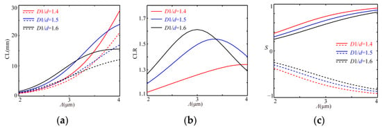
Figure 2.
The variation relations of CLs (a), CLRs (b) and Ss (c) with Λ.
It is clear that all the CLs lengthen with an increase in the Λ (as reference []), in which the CL of r-modes is longer than that of the l-modes for the paired CLs owing to the right chirality of the medium, and all their differences first increase and then decrease. In the region of the small Λ, the paired CLs lengthen and the difference enlarges with an increase in D1/d or Λ thanks to the effect of the (orthogonal) asymmetry. As Λ increases, the CLs lengthen, which is caused by the larger space between the two cores, and because of the circular asymmetry of the cross section, the difference further enlarges. Additionally, with a further increase in Λ, all the mode fields would be localized in the core area where the effect of the orthogonal asymmetry reduces; the effect of chirality effect relatively strengthens; and the paired CLs and their difference lessens, in which the paired CLs decrease and increase for r- and l-modes, respectively. As shown in Figure 2b, the corresponding CLRs first increase and then decrease, in which the maximum values of 1.341, 1.538 and 1.612 emerge at Λ = 4.0 μm, Λ = 3.3 μm and Λ = 3.0 μm for D1/d = 1.4, D1/d = 1.5 and D1/d = 1.6, respectively. A comparison of Figure 2b,c shows that the corresponding S can be obtained with 0.9166/−0.9161, 0.7393/−0.7385 and 0.5726/−0.5719, which means that the larger circular asymmetry of the structure introduced by the larger D1/d leads to a reduction in the paired |S| and an increase in their difference, whereas the paired CLs relatively shorten for the larger D1/d.
In addition, the |S| rise with an increase in the Λ or a decrease in the D1/d. This demonstrates that the realization of CPBS requires increasing the chirality of the medium or decreasing the circular asymmetry of the structure to find a moderate value, such as D1/d = 1.4, where LCr = 28.30 mm and LCl = 21.10 mm, in this case, such that the corresponding CLR can approach to 4/3 by further increasing Λ or δ and ensure that |S| > 0.96, and the corresponding whole length of the PBS may be 80 mm or longer. Thus, its length would be longer than the ordinary LPBS unless there is a medium with stronger chirality and a larger circular asymmetry in its structure, such as the larger D1/d.
Because the closer the core spacing is, the shorter the CL is and the weaker the effect of chirality [], a smaller lattice constant with Λ = 2.0 μm and stronger chirality with δ = 5000δ0 are considered, as shown in Figure 3, in which the relations of CLs (a), CLRs (b) and Ss (c) with D1/d are exhibited, where d is 0.4Λ and D2/d are, respectively, chosen as 1, 1.4 and 1.6. The same color denotes the fiber with identical D2/d, in which the solid and dotted lines respectively indicate the r- and l-modes.
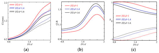
Figure 3.
The variation relations of CLs (a), CLRs (b) and Ss (c) with D1/d.
All the paired CLs lengthen with an increase in the D1/d and a decrease in the D2/d, and their tendencies are the same, in which the CL of the r-modes is longer than that of the corresponding l-modes (see Figure 2a); the paired CLs first bifurcate slowly thanks to the smaller circular asymmetry of the structure (D1/d < 1.2), and then, with an increase in the circular asymmetry of the structure (D1/d > 1.2), the bifurcations rapidly enlarge and decrease after they have reached the maximum. As shown in Figure 3b, the CLRs first slowly rise in the range of D1/d < 1.2, then increase rapidly within 1.2 < D1/d < 1.6 and decrease in the case of 1.75 < D1/d.
From Figure 3c, one can see that all the |S| always lessens with an increase in D1/d, except in the case of D1/d = 1, in which |S| = 1 at D1/d = 1 indicates the weakest circular asymmetry of the structure, and whether D1/d > 1 or D1/d < 1, the value of D1/d away from unity means that the circular asymmetry of the structure strengthens. Thus, all the CLRs are close to unity and the corresponding |S| approaches unity at D1/d < 1.2, which indicates that the CPBS can be realized and its physical length would be very long and that the other region needs a stronger chirality for the medium. For example, the maximum values of CLR with 1.236, 1.362 and 1.376 for D2/d = 1, D2/d = 1.4 and D2/d = 1.6 occur at D1/d ≈ 1.80, D1/d ≈ 1.75 and D1/d ≈ 1.75, so by comparing them to Figure 3c, the S approximately equals to 0.6661/−0.6670, 0.4276/−0.4250 and 0.3911/−0.3886, respectively. This demonstrates that the CPBS can be designed by reducing D1/d and D2/d or increasing Λ and δ. Meanwhile, this suggests that the designed CPBS needs the value of CLR on the left of the maximum value because its |S| is closer to unity.
Figure 4 shows the effect of D2/d on CLs (a), CLRs (b) and Ss (c), where Λ, D1/d and δ are chosen as 2 μm, 1.4 and 5000δ0, respectively, and d/Λ are 0.4, 0.42 and 0.44. The same color describes the fiber with an identical d/Λ and the solid and dotted lines respectively indicate the r- and l-modes.
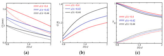
Figure 4.
The variation relations of CLs (a), CLRs (b) and Ss (c) with D2/d.
All the paired CLs shorten with an increase in D2/d or d/Λ thanks to the circular asymmetry of the structure, and their difference rises, whereas the corresponding CLR increases, as shown in Figure 4a,b. The larger air filling rate would distribute more light into the air holes, which decreases the effective indices and their differences in the paired modes; whereas the light localized in the core area can be concentrated in the center of the core, the circular asymmetry of structure is strengthening thanks to the introduction of the tailoring holes, and with an increase in D2/d, the circular asymmetry can further increase; hence, the paired CLs lessen and the CLR rises. This offers a way to reduce the length of the CL and ensure the value of CLR far away from unity to decrease the physical length of the PBS. However, this conflicts with the circular polarization–maintaining property, as shown in Figure 4c, in that with an increase in D2/d or d/Λ, all the |S| are decreasing. The cause is a decrease in the chirality filling rate, as well as the strengthening circular asymmetry of the structure. This demonstrates that designing CPBSs requires increasing the chiral filling rate and decreasing the value of D2/d as it approaches unity, which can ensure that the CLR equals 11/10, 12/11 or some other value close to unity for positive integers with opposite parity to reduce the dependence on the chirality of the medium.
For the case of d/Λ= 0.44 at D2/d = 0.80 and D2/d = 0.85, the CLs for the r-/l-modes are 1.632 mm/1.497 mm and 1.602 mm/1.438 mm; the corresponding CLRs are 1.090 and 1.114 close to 11/10 and 12/11; and the S are, respectively, 0.9222/−0.9226 and 0.8866/−0.8864. For the case of d/Λ = 0.42 around CLR = 11/10 and CLR = 12/11; the values of CLR are equal to 1.102 and 1.116 at D2/d = 1.00 and D2/d = 1.05, the paired CLs are 1.197 mm/1.087 mm and 1.174 mm/1.051 mm with CLR = 1.102 and CLR = 1.117; and the S are 0.8475/−0.8465 and 0.8116/−0.8099, respectively. Additionally, when d/Λ = 0.40, the paired CLs are 0.8550 mm/0.7751 mm and 0.8382 mm/0.7535 mm for D2/d = 1.15 and D2/d = 1.25, and the S are equal to 0.7912/−0.7892 and 0.7282/−7255.
According to the above analysis, the DC-PCF CPBS may be realized with CLR = 11/10 and CLR = 12/11 by increasing the chirality of the medium or tailoring the structural parameters to reduce the circular asymmetry of the structure. Furthermore, around CLR = 11/10 and CLR = 12/11, to reduce the dependence on the chirality, the CPBS can be easily realized with a larger d/Λ, although its filling rate for chirality is smaller; however, its practical length would be long. For the other value of CLR closer to unity, the required chirality of the medium would be weaker, and the length of the CPBS must be longer. The shorter length of the CPBS can be designed with CLR far away from unity unless the chirality of the medium is strong enough.
Figure 5 shows the effect of the filling rate of air (d/Λ), where a larger Λ = 2.5 μm and δ = 5000δ0 are employed to increase the chirality effect, and D1/d and D2/d are, respectively, the same, at 1.4, 1.5 and 1.6.
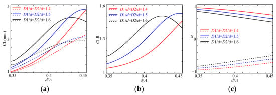
Figure 5.
The variation relations of CLs (a), CLRs (b) and Ss (c) with d/Λ.
In Figure 5a, all the paired CLs have the same variation tendencies, except in the case of D1/d = D2/d = 1.4, thanks to the limitation of the filling rate of air, in which the paired CLs and its differences always rise, and for the other cases, the two-paired CLs and the differences between the paired CLs first increase and then decrease. This is because the larger air holes squeeze the light into the core area to reduce the coupling of the paired modes between the two cores, and the introduction of the tailored holes further enlarges the difference between the paired CLs. By further increasing d/Λ, more light is localized into the core area to further enhance the effect of the tailored holes, such as in Figure 3a and Figure 4a; the differences reduce, as exhibited in Figure 5b; and the lines of the CLRs first rise and then decline.
In addition, with an increase in d/Λ, D1/d or D2/d, all the |S| decrease thanks to a reduction in the filling rate of chirality, as shown in Figure 5c. This indicates that the reduction in the circular asymmetry (smaller D1/d or D2/d) or the filling rate of air would increase the chirality effect. At d/Λ = 0.36, the CLs are, respectively, 1.215 mm/1.154 mm, 1.519 mm/1.378 mm and 1.885 mm/1.597 mm for the paired r-/l-modes; for D1/d = D2/d = 1.4, D1/d = D2/d = 1.5 and D1/d = D2/d = 1.6, the CLRs are, respectively, 1.053, 1.103 and 1.181; and the Ss are, respectively, 0.8968/−0.8950, 0.8405/−0.8382 and 0.7770/−7745. To reduce the dependence on the chirality of the medium, the DC-PCF can be chosen as a CPBS in the case of D1/d = D2/d = 1.4, where the CLR can be designed with 21/20 or with the other values of an integer ratio closer to unity with opposite parity, by further increasing the chirality of the medium or optimizing the structural parameters.
Figure 6 shows the effect of all the tailored holes with the same size, in which the larger Λ is chosen as 2.5 μm, 3 μm and 3.5 μm to reduce the dependence on the chirality of the medium, and d and δ are chosen as 0.4Λ and 5000δ0, respectively.

Figure 6.
The variation relations of CLs (a), CLRs (b) and Ss (c) with D1/d and D2/d.
All the paired CLs and their differences lengthen and then shorten with an increase in D1/d and D2/d, and their maximum values reduce and move to the right with a decrease in Λ. Although the maximum differences for the paired CLs decrease, their ratio increases, as shown in Figure 6b, where they are almost equal at D1/d < 1.5 and D2/d < 1.5, in which they are nearly equal to unity at D1/d < 1.2 and D2/d < 1.2. This suggests that the design of the DC-PCF for the CPBS have to satisfy the conditions of D1/d > 1.2 and D2/d > 1.2; otherwise, the CPBS would be long. When the CLRs with maximum values of 1.471, 1.413 and 1.298 respectively occur at (D1/d=)D2/d = 1.7, (D1/d=)D2/d = 1.6 and (D1/d=)D2/d = 1.55 for Λ = 2.5 μm, Λ = 3 μm and Λ = 3.5 μm, the CLs are, respectively, 2.606 mm/2.147 mm, 7.490 mm/5.300 mm and 12.632 mm/9.728 mm and the corresponding Ss are 0.7810/−0.7775, 0.8715/−0.8687 and 0.9382/0.9364, respectively, in which the third case can be viewed as a nearly CP PBS. This indicates that the CPBS can be manufactured by only optimizing the asymmetry of the structure, strengthening the chirality of the medium or increasing the lattice constant, whereas the practical length of the CPBS would be relatively longer.
In Figure 6c, the values of |S| are larger than 0.96, which respectively emerged at (D1/d=)D2/d = 1.2, (D1/d=)D2/d = 1.3 and (D1/d=)D2/d = 1.42, and the corresponding CLRs are, respectively, smaller at 1.026, 1.058 and 1.191, which means that the CLR can be designed for the third case with 6/5 or 7/6 for a stronger chirality effect, and for two other cases, it should have other values closer to unity for an integer ratio with an opposite parity. In conclusion, the larger Λ can increase the chirality effect and reduce the chirality of the medium, but the length of the CPBS would be long.
To show a reduction in the dependence on chirality and how an appropriate value for CLR is obtained, Figure 7 features the CLs, CLR and Ss for the tailored fiber structure, where the larger Λ with 3.5 μm and a smaller d with 0.36 Λ are selected; the larger D1/d with 1.5 and 1.6 are fixed; and δ is 5000δ0.
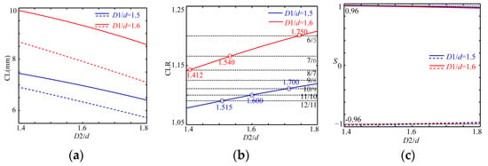
Figure 7.
The variation relations of CLs (a), CLRs (b) and Ss (c) with D2/d for fixed D1/d.
All the CLs are shortened with a decrease in D1/d and an increase in D2/d, which are the same as in Figure 3 and Figure 4. For the case of D1/d = 1.6, the CLRs meet the requirement of the design for the CPBS that approach 8/7, 7/6 and 6/5 at D2/d = 1.412, D2/d = 1.540 and D2/d = 1.750. The corresponding CLs are 9.870 mm/8.635 mm, 9.507 mm/8.148 mm and 8.772 mm/7.304 mm, where the Ss are, respectively, 0.9676/−0.9667, 0.9566/−0.9554 and 0.9342/−9326 for the r- and l-modes, which means that a DC-PCF CPBS can be realized with 69.09 mm with CLR = 8/7 at D2/d = 1.412. Compared to the previous work, the length of the DC-PCF CPBS is 135 mm shorter and the strength of chirality decreases to 46°/mm []. The chirality of the medium can further reduce as long as |S| ≥ 0.96. For the other two values of CLR, the CPBS can be designed with a shorter length as long as it has stronger chirality.
In the case of D1/d = 1.5, the values of CLRs close to 12/11, 11/10 and 10/9 emerge at D2/d = 1.515, D2/d = 1.600 and D2/d = 1.700, respectively; the lengths of the CLs are, respectively, 7.185 mm/6.585 mm, 6.970 mm/6.335 mm and 6.699 mm/6.034 mm, where the Ss are, respectively, 0.9679/−0.9669, 0.9605/−0.9594 and 0.9511/−0.9498; and thus, the DC-PCF CPBS can be obtained with 79.035 mm for CLR = 12/11 and 69.70 mm for 11/10, which are much less than those in the previous work and need a weaker chirality with 46°/mm [], where the chirality strength can be furtherly decreased in the case of CLR = 12/11.
Figure 8 shows the normalized transmission power variation for the RHP and LHP modes along the propagation distance in core A and the corresponding ER for the three CPBSs. After a propagation distance of 69.09 mm and 79.035 mm for the first two CPBSs, the power of the RHP mode is almost completely coupled into core B and the LHP mode remains in core A. Additionally, for the third CPBS, the RHP mode remains in core A, and the LHP mode is fully coupled into core B. Their ERs can respectively reach 160.73 dB, 140.31 dB and 120.00 dB at 1.55 μm, which are larger than those of most LPBSs and the dielectrically chiral DC-PCF CPBS [,] and are far more than of the structurally chiral DC-PCF CPBS [], especially when the first ER is larger than 151.42 dB in the DC-PCF LPBS []. Additionally, the width of the spectra are, respectively, 22 nm, 12 nm and 12 nm when ER > 20 dB, which is smaller than those of most LPBSs and the dielectrically chiral DC-PCF CPBS []; however, it is about twice that of the structurally chiral DC-PCF CPBS []. According to the above analysis, we can know the performance of CPBS 1 is better than that of the other two CPBSs because of the superhigh ER and the wider bandwidth of the spectrum. Furthermore, it demonstrates that the stronger coupling effect can decrease the spectral bandwidth.
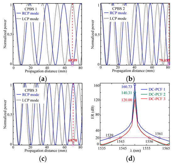
Figure 8.
Normalized power in port A along propagation distance in the chiral PCF CPBSs in (a–c) and the corresponding dependence of the ER on wavelength in (d).
In practical applications of the design, more microstructures can be moderately considered so that the chiral dual-core PCFs have zero or near-zero dispersion around the operation wavelength, so that no additional dispersion is introduced or so that it has a flat dispersion to obtain the wider spectral bandwidth. In addition, it is necessary to consider the mode field of the CPBS to match that of the applied fiber in its design. Otherwise, the loss will be large to decrease the performance of the optic circuit.
Table 1 lists the performance comparison between the proposed and the reported chiral DC-PCF CPBSs. According to Table 1, the CLs for this work are far less than 205.5 mm [] and 24.76 mm [], while the ERs are better than those in the previous work, especially the ER of CPBS 1, which can reach 160 dB, which is higher than that of the reported work. The bandwidth of the spectrum is narrower than 32 nm [], while it is still wider than 11.43 [], especially for CPBS 1, which can reach 22 nm, which is almost twice as much the structurally chiral DC-PCF CPBS []. The chirality strength decreases to 46°/mm, which is far less than that in the previous work [,]. Therefore, the performance of CPBS 1 is better than that of the other two CPBSs. By further optimizing the fiber’s structure or/and enhancing the chirality strength of the medium, the CL would further shorten and the performance would further improve.

Table 1.
Performance comparison between the proposed chiral DC-PCF CPBS and the reported chiral DC-PCF CPBS.
In addition to separating the CP beam with opposite handedness for same wavelengths, the CPBS can also split CP beams with different wavelengths. To ensure that the modes are CP, the structure and medium is employed at above three chiral DC-PCFs, and the dependence of the CL on wavelengths for the LHP mode is considered because the chirality strength is stronger in the shortwave region and because the CL of LHP mode is always shorter than that of the RHP mode for the same wavelength. Figure 9 shows the CLs of the LHP modes with wavelengths for the three chiral DC-PCFs corresponding to Figure 8, which covers the second and third communication window.
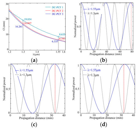
Figure 9.
The variation relation of CLs with wavelengths on the LHP modes for the three DC-PCFs corresponding to Figure 8 in (a) and the normalized power variation along the propagation distance in core A in the three DC-PCFs for λ = 1.55 μm and λ = 1.30 μm in (b–d).
The coupling length also increases by decreasing the operating wavelength with the DC-PCF LPBS [], where the CLs of the LHP modes are, respectively, 8.635 mm, 6.585 mm and 6.335 mm at λ = 1.55 μm and 19.054 mm, 16.867 mm and 16.261 mm at λ = 1.30 μm, and their corresponding ratios are 2.207, 2.561 and 2.460 when approaching 9/4, 5/2, 5/2, which meet the requirement for CLλ1/CLλ2 = odd/even or CLλ1/CLλ2 = even/odd []. This suggests that these fibers can be designed as a multiplexer/demultiplexer for separating the CP beams that approach λ = 1.55 μm and λ = 1.30 μm applied in fiber laser communication systems, and the corresponding physical lengths are, respectively, close to 76.216 mm, 33.734 mm and 32.522 mm, as shown in Figure 9b. The length of the multiplexer/demultiplexer can be made shorter through the further optimization of the structure of the fiber and the chirality of the medium.
4. Conclusions
A kind of efficient CPBS based on chiral DC-PCF was presented and analyzed by using the chiral PWE method, where the shorter distance between the two cores was selected. Based on the competitive effect in CL and the polarization between the circular asymmetry and the chirality of the medium, through the optimization of the structure, the DC-PCF CPBS was obtained for the central wavelength of 1.55 μm. The required chirality strength can decrease to δ = 46°/mm, which is far less than δ = 96°/mm; the CL can shorten to 69.09 mm, which is far less than the previous 205 mm; the width of spectra can reach 22 nm, which can be a little bit narrower than 32 nm when |ER| > 20 dB; and the ER above 160 dB is higher than 120 dB []. This performance of the CPBS was also better than that of the structural CPBS, except that the CL is longer []. Furthermore, on the basis of different wavelengths, the chiral DC-PCFs were discussed as multiplexers/demultiplexers. The simulation demonstrated that the multiplexer/demultiplexer can be perfectly realized for CP beams around 1.55 μm/1.30 μm by further optimizing the structure of the fiber, which has potential applications in circular polarization laser communication systems.
The high-performance circular polarization beam splitter (CPBS) needs a medium with a stronger chirality to tailor the coupling length (CL), extinction ratio (ER) and circular polarization–maintaining characteristics. The chiral medium can be obtained through organic chemical synthesis [,] and the solution-doping technique []. Compared with the structurally chiral CPBS, the chiral dual-core PCF (DC-PCF) can be fabricated as the ordinary achiral one, such as by using the stack-and-draw technique, the drilling method, and so on. With the development of chiral materials and through the further optimization of the fiber structure, the performance of the dielectrically chiral DC-PCF CPBS can be further improved.
The CPBS can be applied in the field of sensors and optical fiber communication as a circular polarization–maintaining device to replace the existing LPBS and quarter-wave plates, to reduce the polarization error/noise and to oppositely split CP light and CP multiplexer/demultiplexer in fiber laser communication systems.
Author Contributions
Conceptualization, S.L. and Y.L.; methodology, S.L.; software, C.J.; validation, S.L.; formal analysis, H.G. and C.J.; investigation, S.L. and H.L.; resources, Y.L. and H.L.; data curation, S.L. and Y.L.; writing—original draft preparation, S.L.; writing—review and editing, S.L.; visualization, Q.S.; supervision, Y.L. and S.L.; project administration, S.L. and Q.S.; funding acquisition, Y.L. All authors have read and agreed to the published version of the manuscript.
Funding
This research was funded by the Fundamental Research Funds for the Central Universities under grant no. 3072022CF0806.
Institutional Review Board Statement
Not applicable.
Informed Consent Statement
Not applicable.
Data Availability Statement
Not applicable.
Conflicts of Interest
The authors declare no conflict of interest.
References
- Saitoh, K.; Sato, Y.; Koshiba, M. Coupling characteristics of dual-core photonic crystal fiber couplers. Opt. Express 2003, 11, 3188–3195. [Google Scholar] [CrossRef]
- Zhang, L.; Yang, C. Polarization splitter based on photonic crystal fibers. Opt. Express 2003, 11, 1015–1020. [Google Scholar] [CrossRef] [PubMed]
- Lin, Z.; Yang, C.; Yu, C.; Luo, T.; Alan, E. PCF-based polarization splitters with simplified structures. J. Light. Technol. 2005, 23, 3558–3565. [Google Scholar]
- Hu, D.; Ping, S.; Chao, L.; Sun, X.; Ren, G.; Xia, Y.; Wang, G. Design and analysis of thermally tunable liquid crystal filled hybrid photonic crystal fiber coupler. Opt. Commun. 2009, 282, 2343–2347. [Google Scholar] [CrossRef]
- Zhang, S.; Yu, X.; Zhang, Y.; Shum, P.; Zhang, Y.; Xia, L.; Liu, D. Theoretical study of dual-core photonic crystal fibers with metal wire. IEEE Photonics J. 2012, 4, 1178–1187. [Google Scholar] [CrossRef]
- Suga-Restrepo, J.E.; Guimares, W.M.; Franco, M. All-fiber circular polarization beam splitter based on helically twisted twin-core photonic crystal fiber coupler. Opt. Fiber Technol. 2020, 58, 102285. [Google Scholar] [CrossRef]
- Jiang, H.; Wang, E.; Zhang, J.; Lei, H.; Mao, Q.; Li, Q.; Xie, K. Polarization splitter based on dual-core photonic crystal fiber. Opt. Express 2014, 22, 30461–30466. [Google Scholar] [CrossRef] [PubMed]
- Xu, Z.; Li, X.; Ling, W.; Liu, P.; Zhang, Z. Design of short polarization splitter based on dual-core photonic crystal fiber with ultra-high extinction ratio. Opt. Commun. 2015, 354, 314–320. [Google Scholar] [CrossRef]
- Sheng, Z.; Wang, J.; Feng, R. Design of a compact polarization splitter based on the dual-elliptical-core photonic crystal fiber. Infrared Phys. Technol. 2014, 67, 560–565. [Google Scholar] [CrossRef]
- Zou, H.; Xiong, H.; Zhang, Y.S.; Ma, Y.; Zheng, J.J. Ultra-broadband polarization splitter based on graphene layer-filled dual-core photonic crystal fiber. Chin. Phys. B 2017, 26, 124216. [Google Scholar] [CrossRef]
- Zi, J.; Li, S.; Wang, G.; An, G.; Fan, Z. Design of ultra-short polarization beam splitter based on liquid-filled photonic crystal fiber. Opt. Quantum Electron. 2016, 48, 233. [Google Scholar] [CrossRef]
- Dou, C.; Jing, X.; Li, S.; Wu, J.; Wang, Q. A compact and low-loss polarization splitter based on dual-core photonic crystal fiber. Opt. Quantum Electron. 2018, 50, 255. [Google Scholar] [CrossRef]
- Xu, Q.; Zhao, Y.; Xia, H.; Lin, S.; Zhang, Y. Ultrashort polarization splitter on dual-core photonic crystal fibers with gold wire. Opt. Eng. 2018, 57, 46104. [Google Scholar] [CrossRef]
- Younis, B.M.; Hameed, M.F.O.; Obayya, S.S.A. Tunable polarization splitter based on asymmetric dual-core liquid photonic crystal fiber. Opt. Quantum Electron. 2021, 53, 51. [Google Scholar] [CrossRef]
- Chu, L.; Liu, M.; Shum, P.; Fu, Y. Simultaneous achievement of an ultrashort length and a high extinction ratio polarization splitter based on the dual-core photonic crystal fiber with Ge20Sb15Se65 glass. Appl. Opt. 2019, 58, 7892–7896. [Google Scholar] [CrossRef] [PubMed]
- Lou, J.; Yang, Y.; Zhang, X.; Qu, Q.; Li, S. Ultra-Short Dual-Core Photonic Crystal Fiber Polarization Beam Splitter with Round Lattice and As2S3-Filled Center Air Hole. Photonics 2022, 9, 36. [Google Scholar] [CrossRef]
- Sanders, G.A.; Demma, N.; Rouse, G.F.; Smith, R.B. Evaluation of polarization maintaining fiber resonator for rotation sensing applications. In Optical Fiber Sensors; Optica Publishing Group: Washington, DC, USA, 1988; p. FBB7. [Google Scholar]
- Wang, X.; He, Z.; Hotate, K. Polarization-noise suppression by twice 90-degree polarization-axis rotated splicing in resonator fiber optic gyroscope. In Proceedings of the Conference on Lasers & Electro-Optics, Baltimore, MD, USA, 2–4 June 2009. [Google Scholar]
- Wang, Z.; Wang, G.; Wang, Z.; Gao, W.; Cheng, Y. Incoherence suppression method of optical noises in resonant fiber optic gyro based on the circularly polarized light propagation mechanism in resonator. Opt. Lett. 2021, 46, 3191–3194. [Google Scholar] [CrossRef]
- Gao, H.; Wang, G.; Gao, W.; Li, S. A chiral photonic crystal fiber sensing coil for decreasing the polarization error in a fiber optic current sensor. Opt. Commun. 2020, 469, 125755. [Google Scholar] [CrossRef]
- Gao, W.; Gao, H.; Xia, X.; Wang, G.; Li, S.; Zhao, Y.; Wang, Y. Design of a dielectric chiral micro-structured fiber applied in a fiber optic current sensor. Opt. Contin. 2022, 1, 271–282. [Google Scholar] [CrossRef]
- Tentroi, D.; Treviño-Martínez, F.; Ayala-Díaz, C.; Mendieta-Jiménez, F.J.; Tentori, D. Birefringence assessment of single-mode optical fibers. Opt Express 2005, 13, 2556–2563. [Google Scholar]
- Kopp, V.I.; Park, J.; Wlodawski, M.; Singer, J.; Neugroschl, D.; Genack, A.Z. Chiral Fibers: Microformed Optical Waveguides for Polarization Control, Sensing, Coupling, Amplification, and Switching. J. Light. Technol. 2014, 32, 605–613. [Google Scholar] [CrossRef]
- Kopp, V.I.; Genack, A.Z. Double-helix chiral fibers. Opt. Lett. 2003, 28, 1876–1878. [Google Scholar] [CrossRef] [PubMed]
- Kopp, V.I.; Churikov, V.M.; Singer, J.; Chao, N.; Neugroschl, D.; Genack, A.Z. Chiral fiber gratings. Science 2004, 305, 74–75. [Google Scholar] [CrossRef] [PubMed]
- Peng, N.; Huang, Y.; Wang, S.B.; Wen, T.; Liu, W.; Zuo, Q.; Wang, L. Fiber optic current sensor based on special spun highly birefringent fiber. IEEE Photonics Technol. Lett. 2013, 25, 1668–1671. [Google Scholar] [CrossRef]
- Li, J.Q.; Su, Q.Y.; Cao, Y.S. Circularly polarized guided modes in dielectrically chiral photonic crystal fiber. Opt. Lett. 2010, 35, 2720–2722. [Google Scholar] [CrossRef]
- Li, S.; Li, J.Q. Chiral photonic crystal fibers with single mode and single polarization. Opt. Commun. 2015, 356, 96–102. [Google Scholar] [CrossRef]
- Li, S.; Li, J.Q.; Cao, Y.S. Guided modes in squeezed chiral microstructured fibers. Opt. Commun. 2015, 341, 79–84. [Google Scholar] [CrossRef]
- Argyros, A.; Straton, M.; Docherty, A.; Min, E.H.; Ge, Z.; Wong, K.H.; Ladouceur, F.; Poladian, L. Consideration of chiral optical fibres. Front. Optoelectron. China 2010, 3, 67–70. [Google Scholar] [CrossRef]
- Min, E.H.; Wong, K.H.; Setijadi, E.; Ladouceur, F.; Straton, M.; Argyros, A. Menthol-based chiral copolymers for polymer optical fibres (POF). Polym. Chem. 2011, 2, 2045–2051. [Google Scholar] [CrossRef]
- Li, S.; Li, Y.; Sun, Q.; Gao, H.; Ji, C.; Lv, H. Circular-polarized beam splitter Based on dielectrically chiral dual-core photonic crystal fiber. Opt. Contin. 2022, 1, 2442–2552. [Google Scholar] [CrossRef]
- Gao, F.; Luo, S.; Ji, H.M.; Yang, X.G.; Liang, P.; Yang, T. Broadband tunable InAs/InP quantum dot external-cavity laser emitting around 1.55 μm. Opt. Express 2015, 23, 18493–18500. [Google Scholar] [CrossRef] [PubMed]
- Jopson, R.M.; Eisenstein, G.; Whalen, M.S.; Hall, K.L.; Koren, U.; Simpson, J.R. A 1.55-μm semiconductor-optical fiber ring laser. Appl. Phys. Lett. 1986, 48, 204–206. [Google Scholar] [CrossRef]
- Zheng, Z.; He, C.; Wen, Y.; Li, H. Performance Tunable Passively Q-switched Fiber Laser Based on Single Wall Carbon Nanotube. Mod. Phys. Lett. B 2022, 36, 2250054. [Google Scholar] [CrossRef]
- Huffaker, D.L.; Park, G.; Zou, Z.; Shchekin, O.B.; Deppe, D.G. 1.3 μm room-temperature gaas-based quantum-dot laser. Appl. Phys. Lett. 1998, 73, 2564–2566. [Google Scholar] [CrossRef]
- Liu, M.; Shi, J.; Ma, D.; Jin, E.; Li, S. 1.3 μm high-power superluminescent diode. Semicond. Photonics Technol. 1995, 1, 67–70. [Google Scholar]
- Wen, Y.; He, C.; Zheng, J.; Fang, Y. Passively Q-switched erbium-doped fiber laser based on carbon nanotube saturable absorber. Proc. SPIE 2022, 12478, 1247810. [Google Scholar]
- Ferrando, A.; Silvestre, E.; Miret, J.J.; Andrés, P. Nearly zero ultraflattened dispersion in photonic crystal fibers. Opt. Lett. 2000, 25, 790–792. [Google Scholar] [CrossRef] [PubMed]
- Wang, W.; Hou, L.T.; Ming, L.; Zhou, G.Y. Design of double cladding nearly zero dispersion flattened nonlinear photonic crystal fiber. Chin. Phys. Lett. 2009, 26, 114205. [Google Scholar]
- Liu, Z.; Hou, L.; Wang, W. Tailoring nonlinearity and dispersion of photonic crystal fibers using hybrid cladding. Braz. J. Phys. 2009, 39, 50–54. [Google Scholar]
- Ishigure, T.; Nihei, E.; Koike, Y. Optimum refractive-index profile of the graded-index polymer optical fiber, toward gigabit data links. Appl. Opt. 1996, 35, 2048–2053. [Google Scholar] [CrossRef]
- Large, M.; Ponrathnam, S.; Argyros, A.; Pujari, N.S.; Cox, F. Solution doping of microstructured polymer optical fibres. Opt. Express 2004, 12, 1966–1971. [Google Scholar] [CrossRef] [PubMed]
- Pan, X.F.; Tao, W.D.; Yan, F.B.; Bai, G.R. Fabrication of PMMA doped with griseofulvin material and its optical rotatory dispersion. Optoelectron. Lett. 2006, 2, 41–43. [Google Scholar] [CrossRef]
Disclaimer/Publisher’s Note: The statements, opinions and data contained in all publications are solely those of the individual author(s) and contributor(s) and not of MDPI and/or the editor(s). MDPI and/or the editor(s) disclaim responsibility for any injury to people or property resulting from any ideas, methods, instructions or products referred to in the content. |
© 2023 by the authors. Licensee MDPI, Basel, Switzerland. This article is an open access article distributed under the terms and conditions of the Creative Commons Attribution (CC BY) license (https://creativecommons.org/licenses/by/4.0/).