Communication

Nitrogen-Doped Nickel Graphene Core Shell Synthesis: Structural, Morphological, and Chemical Composition for Planar Hybrid Solar Cells Application

1
Research and Development Center, Korea Carbon Industry Promotion Agency, 110-11, Banryong-Ro, Deokjin-Gu, Jeonju-Si 54853, Republic of Korea
2
Department of Physics, Kyungpook National University, 80 Daehakro, Bukgu, Daegu 41566, Republic of Korea
3
School of Chemical Engineering, Yeungnam University, 280 Daehak-ro, Gyeongsan 38541, Republic of Korea
*
Author to whom correspondence should be addressed.
These authors contributed equally to this work.
Photonics 2023, 10(1), 18; https://doi.org/10.3390/photonics10010018
Submission received: 2 November 2022 / Revised: 1 December 2022 / Accepted: 21 December 2022 / Published: 24 December 2022
(This article belongs to the Special Issue Recent Progress in Solar Cell Technology and Future Prospects)

Abstract

:
In this study, nitrogen-doped nickel graphene core cells (N-NiGR) are synthesized using the thermal chemical vapor deposition method. The structural, morphological, and chemical composition properties of N-NiGR are investigated using X-ray diffractometry (XRD), transmission electron microscopy (TEM), and X-ray photoelectron spectroscopy (XPS), respectively. N-NiGR has shown potential as a material that can assist charge carrier transportation in the photoactive a layer of planar hybrid solar cell (PHSC) owing to its high charge carrier mobility and stability with the solution process. Here, we investigated for the first time an enhancement of the solar cell efficiency (by up to a 2% increase) in PHSCs by incorporating the charge selective N-NiGR into the device’s photoactive layer. Synthesized N-NiGR with different concentrations are incorporated into the active layer of the devices as charge transport material. The device structure of an ITO-coated glass/Hole transport layer/(PBT7+N-NiGR+SnS)/Electron transport layer/Cathode is fabricated and the maximum power conversion efficiency of the device was observed to be about 4.35%.

1. Introduction

Colloidal quantum dots (Qdots) are wet solution-synthesized nanoparticles of most any semiconductor materials, and their optical electronic properties are tunable by the shape, size, and surfactant. Conventionally, Qdots are prepared as colloids in organic solvents using the hot injection method [1]. Initial investigation of the Qdots-based photovoltaics involved planar hybrid solar cells (PHSCs) of CdSe nanocrystals with conducting polymer poly(3-hexylthiophene) (P3HT) as the p-type material [2]. Recently, many types of Qdots have been synthesized, such as CdS, CdSe, PbS, PbSe, and SnS, and have been used in the development of hybrid solar cells [3,4,5]. Tin sulfide (SnS and SnS2) quantum dots are the first class of solution-processed semiconductor nanoparticles that are used as acceptor materials in thin film solar cells with high-conducting polymers. However, the device efficiency was still low for many reasons, such as the presence of surface-related defects, trap states, and charge trapping [6,7,8]. Low charge carrier mobility and low Ohmic contact between the photoactive layer and the electrodes are the main factors to the underlying low efficiency of device performance. To address these problems, several materials, such as MoO3, NiO, V2O5, and WO3, have been used as hole transport buffer layers (HTBL) [9].
Graphene is an appropriate material to add into a solar cell’s photoactive layer because of its high charge mobility, solution processability, and thermal stability [10,11,12,13].
The incorporation of graphene oxide (GO) (or reduced-GO) as a HTBL system has been applied to organic solar cells [10]. The incorporation of GO (or reduced-GO) into HTBL plays an important role in increasing the power conversion efficiency and stability of the organic polymer solar cells. The authors concluded that the solution-processed GO incorporated into HTBL is a promising interfacial material for use in organic photovoltaics.
When the nitrogen-doped graphene is incorporated in the photoactive layer (N-GR/polymer:PCBM), it provided a penetration pathways of charge carriers through the modulation of the band gap structure, which led to an improvement of the device efficiency [11]. The number of electrons transported in the active layer is higher than the number of holes transported. The incorporation of N-GR for better electron transport makes the overall charge transport more imbalanced, and the extraction of electrons prevented the recombination of electrons and holes.
Recently, nickel graphene (NiGR) core-shell nanostructures were synthesized and added to the composite layer of the inorganic planar hybrid photovoltaic [12,13]. The solar cell device with NiGR showed a better performance because NiGR was used as an electron transport material, supporting electron transport between n-type inorganic materials. The incorporation of NiGR enhanced the power conversion efficiency of the hybrid solar cells owing to the higher charge carrier mobility of the nickel graphene core-shell (NiGR) with carrier charge selectivity.
In this study, nitrogen-doped nickel graphene core-shell (N-NiGR) was synthesized and characterized. The chemical composition of graphene in the NiGR CSNPs was investigated using the Raman spectroscopy technique. The synthesized Ni-NGR was applied to planar hybrid solar cells as an electron transport material. Tin sulfide (SnS) was used as acceptor material and poly [4,8-bis(2-ethylhexyloxyl) benzo[1,2-b:4,5-b′]-dithiophene-2,6-diyl-alt- ethylhexyl-3-fluorothieno[3,4-b] thiophene-2-carboxylate-4,6-diyl] (PBT7) was used as donor material. The device with a structure of ITO-coated glass/PEDOT:PSS/(SnS+N-NiGR+PBT7) /ZnO/E-GaIn was fabricated.

2. Materials and Methods

2.1. Nitrogen-Doped Ni-Graphene Core-Shell Nanoparticles Preparation

The effects of the NH3 flow (0, 150, 200, 250, and 300 sccm) on the formation of graphene shells on Ni NPs were studied to evaluate the properties of the nitrogen-doped core-shell structure. The NiO NPs were selected for a short synthesis time of graphene shell formation of ~1 min at high temperature (~1000 °C). The nitrogen-doped Ni-graphene CSs were synthesized by thermal chemical vapor deposition on NiO NPs using a gas mixture. The gas mixture comprised carbon source gas (C2H2), carrier gas (Ar), reduction gas (H2), and nitrogen doping gas (NH3). An alumina boat (40 mm × 120 mm × 10 mm) loaded with NiO nanoparticles was placed on the side (non-heated cooling zone) of a quartz tube furnace, and the furnace was pumped down to 0.67 Pa. After increasing the temperature up to 1100 °C, a gas mixture of C2H2 (20 sccm), Ar (500 sccm), and H2 (500 sccm) was introduced into the heated furnace. At the same time, to control the nitrogen doping ratio, NH3 was used with volumes of 0, 150, 200, 250, and 300 sccm, respectively. The synthesis time of N-NiGR CSNPs was 60 sec for all synthesis condition. After synthesis, the NiGR NPs were rapidly moved to a cooling zone at room temperature under a gas mixture of H2 and Ar.

2.2. Characterization of Nitrogen-Doped Ni-Graphene CSNPs

The structural property analysis of the nitrogen-doped Ni-graphene CSNPs was performed by X-ray diffraction (PANalytical MPD). The XRD analysis was measured using θ–2θ mode in the range 10° ≤ 2θ ≤ 80° by scanning in increments of 0.01°. The surface bonding states of the nitrogen-doped Ni-graphene CSNPs were performed by X-ray photoelectron spectroscopy (ThermoFisher, KA1149). The Raman analysis (Thermo Scientific Nicolet Almega XR) was performed with 532 nm wavelength incident light and the vibrational properties of the N-NiGR CSNPs were evaluated. The surface morphology and microstructure of the nitrogen-doped Ni-graphene CSNPs were obtained using a transmission electron microscope (FEI Tecnai G2 F20).

2.3. The Electron Transfer Layer Preparation for Planar Hybrid Solar Cells Application

The N-NiGR (at 300 sccm) NPs with different weights were added to 3 mL of chlorobenzene (CB) and stirred overnight. Then, a mixture of SnS+ PBT7 (weight ratio (1:4), loading amount: 10 mg/mL) in CB-N-NiGR NPs solvent was prepared. The composite films ((N-NiGR) + SnS + PBT7) were coated on top of the PEDOT:PSS layer (2000 rpm, 60 s). The planar hybrid device with a structure of glass/ITO/PEDOT:PSS/(PBT7+N-NiGR+SnS)/ZnO/E-GaIn was fabricated. A hole transport layer of PEDOT:PSS (~70 nm) was deposited on the glass/ITO (4000 rpm, 30 seconds) and dried at 100 °C for 30 minutes. The thin layer of (SnS+N-NiGR+ PTB7) was deposited onto the glass/ITO/PEDOT:PSS layers (2000 rpm, 60 seconds) then dried at 140 °C for 30 min to form the composite layers. Finally, the cathode (E-GaIn) was coated using a none vacuum method to complete the cell structure of the Glass/ITO//PEDOT:PSS/(PBT7+N-NiGR+SnS)/ZnO/E-GaIn. The device’s parameters, such as the short circuit density (Jsc), fill factor (FF), open circuit voltage (Voc), and power conversion efficiency (PCE) were measured using a solar simulator (Keithley 69911) under AM1.5G illumination conditions.

3. Results and Discussions

XRD measurements were performed to study the structure and phase composition of synthesized N-NiGR CSNPs samples according to the NH3 flow amount. The XRD pattern results of the nitrogen-doped Ni-graphene CSNPs, synthesized at different NH3 flow amounts, are shown in Figure 1a. Before the graphene CS synthesis of Ni-graphene CSNPs (bottom figure in Figure 1a), the NiO had a phase structure with crystal planes of (111), (200), (220), and (311) corresponding to the peaks of 37.2°, 43.3°, 62.8°, and 75.3°, respectively, which is in accordance with that of the standard spectrum (JCPDS card no. 47-1049). After the graphene CS synthesis of Ni-graphene CSNPs, the characteristic peaks of the NiO planes disappeared, and Ni crystal planes appeared for all Ni-graphene CSNP samples prepared at NH3 flow rate amounts of over 150 sccm. These transformations in the XRD pattern results indicate the changes of crystallinity and phase due to the reduction by H2 annealing at high temperature in NiO NPs [14,15]. The diffraction peaks were located at 44.4°, 51.8°, and 76.3°, which are respectively attributed to the (111), (200), and (220) of Ni planes in the face-centered cubic phase of crystalline Ni (JCPDS card no. 04-0850). When the NH3 (0 sccm) flowed, the Ni-graphene CSNPs was confirmed to be a carbon peak. The diffraction peaks located at 26.5° can be attributed to the (002) crystal plane of the graphitic structure (JCPDS card no. 41-1487); the (002) carbon peak refers to a crystalline carbon structure such as graphite, carbon nanotubes, or graphene sheets [16,17]. The carbon (002) peak was not confirmed by the NH3 flow amount. Figure 1b shows the (111) peak of Ni diffraction peak positions. The XRD diffraction peaks of NH3 flowed Ni-graphene CSNPs showed additional peaks with a negative shift of 0.1° from the pure Ni metal peaks. These additional shift diffraction peaks, which are due to the expansion of the Ni crystal lattice, provide further evidence for the incorporation of N atoms by NH3 into the crystal lattice of the Ni metal [18]. Additional peaks by these N atoms were also confirmed as Ni (200) and (220) peaks.
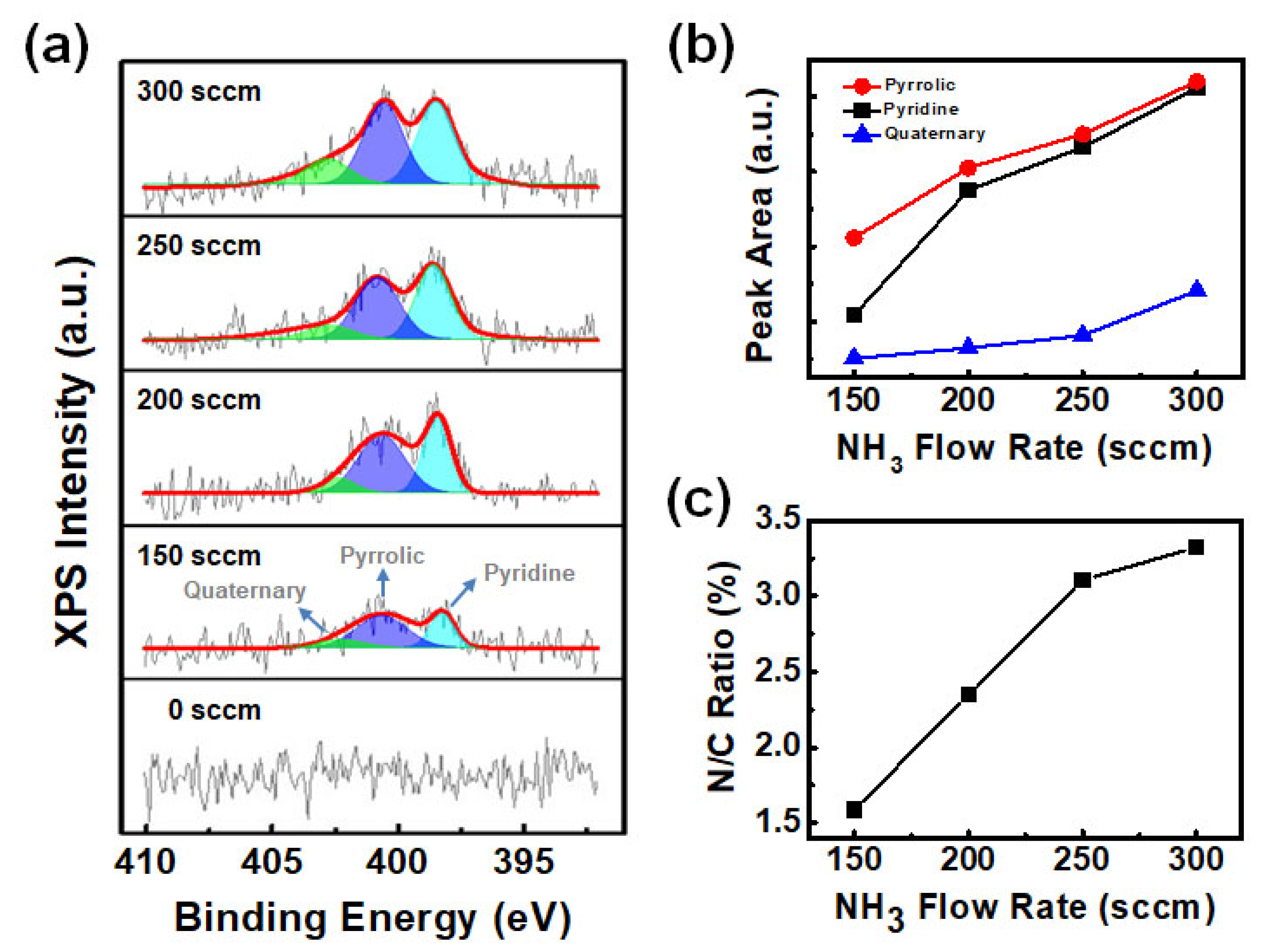
Figure 2 depicts the N 1 s of XPS spectra for the N-NiGR core-shell particles synthesized according to the NH3 flow amount. The N 1 s XPS spectra intensity and area gradually increased with an increasing of NH3 flow amount, as shown in Figure 2a. This means that there are various carbon bonds by nitrogen in the NiGR CSNPs, and there are variations in the contained quantity of each bond upon changing the NH3 flow amount. There are five possible N–C bonding configuration groups of N-doped graphene, and these are classified as quaternary (or graphitic), pyrrolic, oxidated-N, nitrile-N, and pyridine nitrogen bonding [19]. Quaternary carbon bonding is by a nitrogen atom that substitutes for carbon atoms position in the carbon hexagonal rings. The pyrrolic carbon bonding is done by a nitrogen atom that substitutes into the five-membered ring and contributes two p electrons to the π system, while pyridine carbon bonding is by a nitrogen atom that substitutes within the two carbon atoms position at the edges or defects of graphene and contributes one p electron to the π system [20,21]. Under non-NH3 flow amount, the Ni-graphene CSNPs were not confirmed to have all three kinds of nitrogen bonding. The Ni-graphene CSNPs synthesized according to the a NH3 flow amount contain all three types bonding by carbon and nitrogen atoms, as shown in Figure 2b. Among these bonds, pyrrolic and pyridine carbon-nitrogen bonds are noticeably increased in a NH3 flow of over 150 sccm. The ratio of quaternary nitrogen bond increased for a NH3 flow of 300 sccm compared to different NH3 flow amount. Figure 2c shows the total concentration of nitrogen compared to carbon for synthesized NiGR CSNPs according to the NH3 flow amount. The nitrogen concentration in synthesized NiGR CSNPs gradually increased with an increasing NH3 flow amount. This means that synthesized N-NiGR CSNPs have various carbon bonds between carbon and nitrogen atoms, and there are variations in the N/C concentration of each carbon bond upon changing the NH3 flow amount. Thus, the changing of the NH3 flow amount significantly impacts the N-doping concentration of the synthesized Ni-graphene CSNPs.
The purity of graphene layers in the synthesized N-NiGR CSNPs was obtained using the Raman spectroscopy technique. Figure 3 shows the Raman spectroscopy result of the synthesized N-NiGR CSNPs according to the NH3 flow amount. Bands in the range of 2400–3230 cm−1 correspond to the overtone modes of the D- and the G-bands of sp2 carbons bonds. The main components of the carbon material sp2 bond in the Raman spectra was confirmed to be the D-band (~1350 cm−1) and G-band (~1580 cm−1). The vibrations of the six-membered rings in carbon bonds are related to the D-band, whereas the vibrations of the C=C chain clusters are related to the G-band. The 2D bands at ~2700 cm−1 are the result of second-order Raman scattering at almost twice the frequency of the D-band [14,22]. The intensity ratio of D- and G-bands (ID/IG) has been widely used as an indicator of the degree of disorder in various carbon materials. The ID/IG appears in direct proportion to the degree of disorder and is inversely proportional to the crystallinity in carbon materials. Figure 3b shows that ID/IG increases with an increasing NH3 flow amount, indicating a decrease in the degree of crystallinity of the graphene layers in the synthesized N-NiGR CSNPs. This is due to the doping effect in graphene layers by nitrogen atoms. The nitrogen atoms bind to the carbon bonds and result in a decrease in the degree of crystallinity of the graphene layers in the synthesized N-NiGR CSNPs. The intensity ratio of the 2D and G peaks (I2D/IG) depends on the number of graphene layers [14,23]. Typically, the I2D/IG ratio is ~2–3 for monolayer graphene, 2 > I2D/IG > 1 for bilayer graphene, and I2D/IG < 1 for multilayer graphene [14]. An I2D/IG of ~0.8 is reported to correspond to a few-layered graphene [14,24]. The I2D/IG ratio of the N-NiGR CSNPs decreases from 0.79 to 0.43 with an increasing NH3 flow amount (Figure 3c). This indicates that the number of graphene layers increases according to the increasing NH3 flow amount in the synthesized N-NiGR CSNPs.
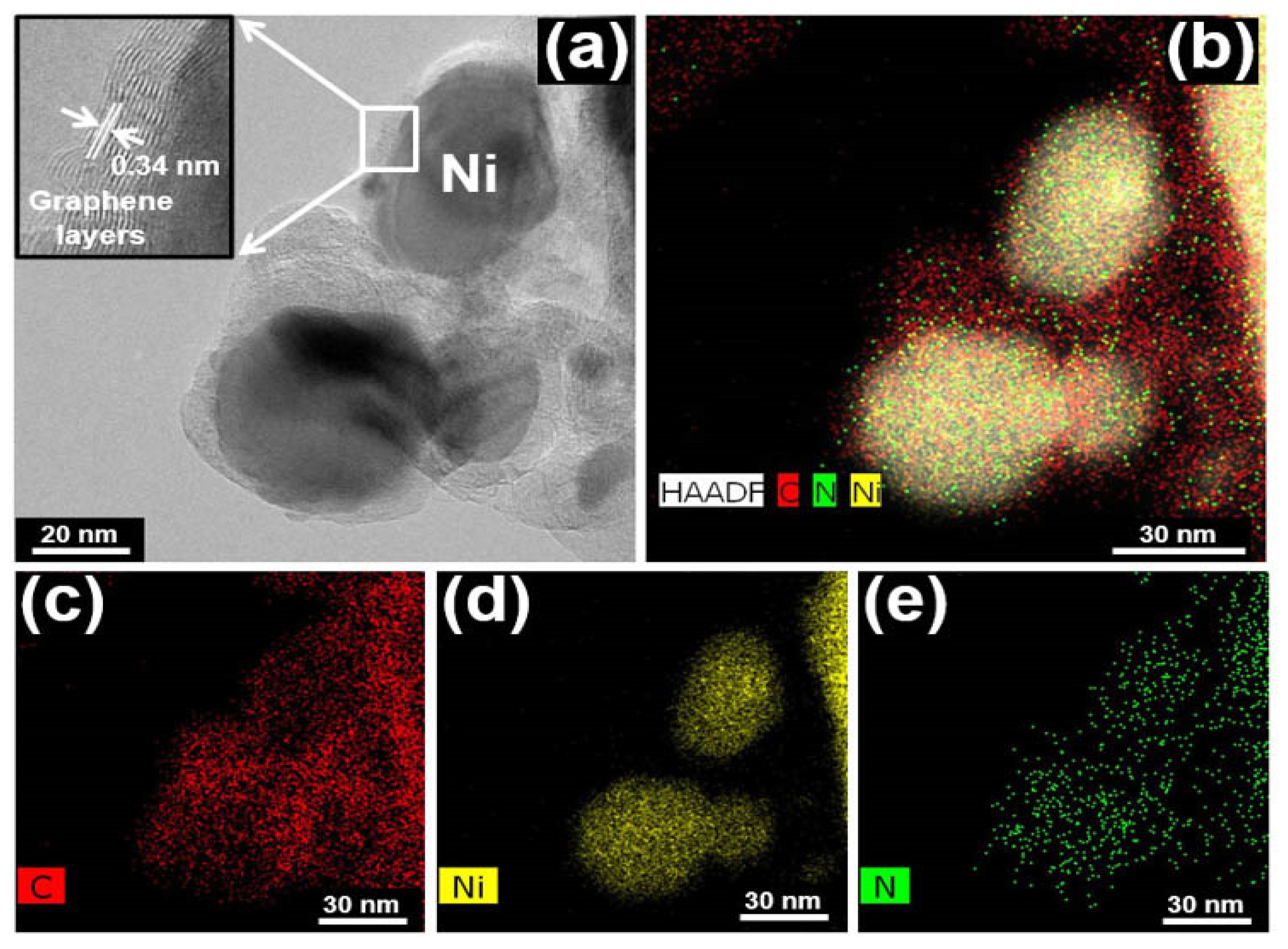
Figure 4 depicts the TEM and C, N, and Ni mapping images of the N-NiGR CSNPs at an NH3 flow amount of 300 sccm. Figure 4a shows a low-resolution image of N-NiGR CSNPs, and the inset of Figure 4a clearly shows a high-resolution image of N-NiGR CSNPs surface. The Ni NP of synthesized N-NiGR CSNP was wrapped with multiple layer (12 layer) graphene. The distance between two graphene layers is approximately 0.34 nm (Figure 4a inner box), which is agreement with the theoretical interlayer distance of (002) planes of hexagonal graphite (d002 = 0.335 nm) [14,25]. The size of Ni NPs inside N-NiGR CSNPs and the number of layers of graphene on the Ni NPs surface were not uniform even in synthesized N-NiGR CSNPs at the same NH3 flow rate.
The transmission electron microscope and high-resolution (HR-TEM) images of Ni-NGR CSNPs are shown in Figure 4a, revealing the successful preparation of high-quality Ni-NGR CSNPs. Figure 4b–e further shows that the elemental mapping of nanostructures confirms the uniformity of the Ni-NGR nanocrystalline structure. The chemical composition and structural properties were investigated in the above results using XPS, Raman, and XRD, and confirm the uniform distribution of N elements throughout the N-NiGR CSNPs.
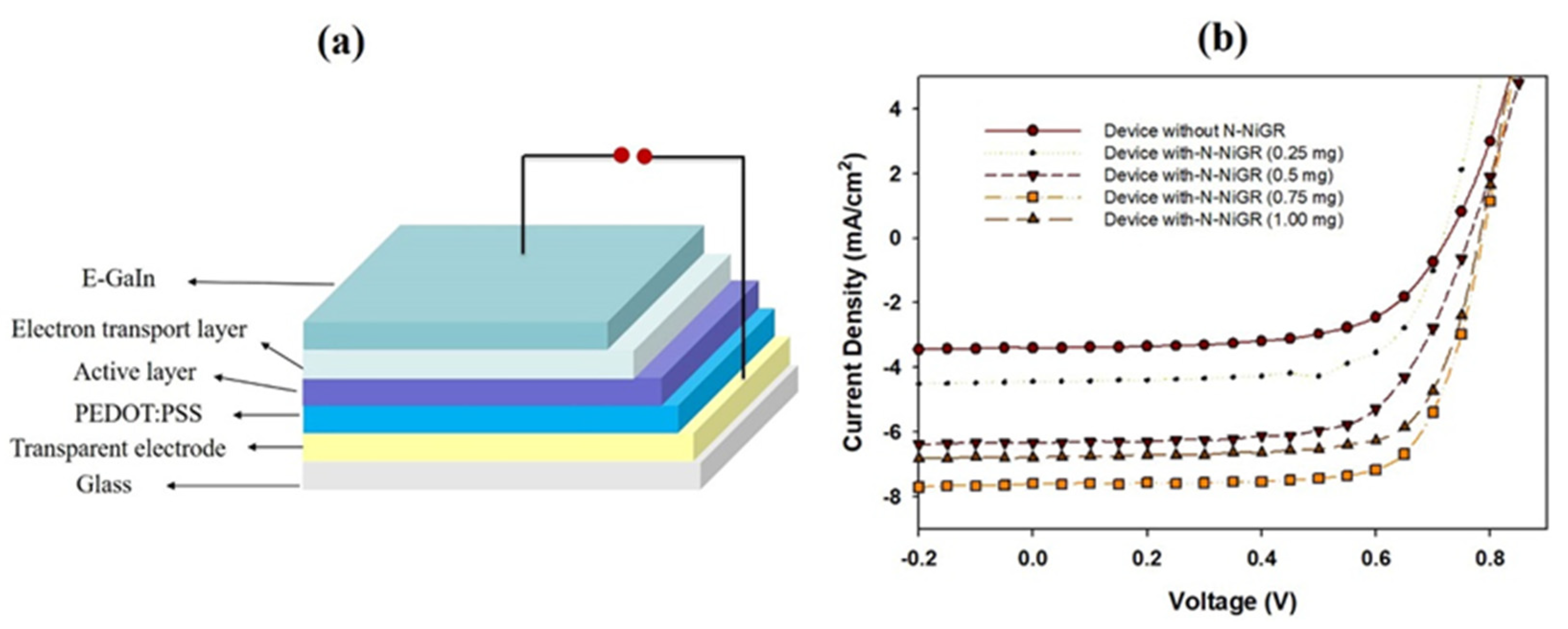
The synthesized N-NiGR NPs with different concentrations were applied to planar hybrid solar cells as electron transport material, as shown in the Figure 5 and Table 1. Figure 5 depicts the J–V curves characterization of the device without and with N-NiGR NPs with different of loading amount (wt%). The cells with a structure of Glass/ITO/PEDOT:PSS/(PBT7 + N-NiGR + SnS)/ZnO/ E-GaIn depict an efficiency of 1.53% (Jsc = 3.40 mA/cm2) for devices without N-NiGR, 2.12% (Jsc = 4.40 mA/cm2) for devices with N-NiGR (0.25 mg of wt.%), 3.78% (Jsc = 6.80 mA/cm2) for devices with N-NiGR (0.5 mg of wt.%), 4.35% (Jsc = 7.60 mA/cm2) for device with N-NiGR (0.75 mg of wt.%), and 3.16% (Jsc = 6.30 mA/cm2) for devices with N-NiGR (1 mg of wt.%).
Figure 5 shows that the efficiencies of the cell were increased from 2.12 to 4.35% as the concentration of N-NiGR varied from 0.25 to 1 mg. The PCE values of these cells were also larger than that of the cell using the (PBT7:SnS) layer without N-NiGR NPs. The results show that the N-NiGR NPs, which functioned as the electron transport material that supported the improvement in the electron transport between the tin sulfide molecules, led to an improvement of the penetration pathway and charge transport rate, and a decrease of the recombination at the electrode, thus, improving the cell performance was improved [11,26,27,28]. The cell PCE was enhanced because of the increase of the current density from 4.40 to 6.30 mA/cm2.
We have fabricated SnS quantum dots solar cells based on an N-NiGR/PBT7/SnS hetero-junction structure with a PCE of up to 4.35%. This is the highest achieved efficiency value of SnS solar cells, compared with a recorded efficiency of 3.0% which was reported by Dong Ding et al. [6]. The performance of the devices was found to be enhanced by the incorporation of N-NiGR, which functions as electron charge transport material. Further, the low band gap polymer as PBT7 was used as light absorption material, which can improve of the optical property of the device’s active layer.

4. Conclusions

The N-NiGR NPs were successfully synthesized, characterized, and applied to the SnS/PBT7 planar hybrid solar cells as electron transport material. The device with N-NiGR NPs showed a larger PCE than the device without N-NiGR NPs. The device with 0.75 mg of N-NiGR NPs showed a highest power conversion efficiency of about 4.35% (Voc = 0.77 (V), Jsc = 7.60 mA/cm2; FF = 72). We believe that the incorporated functionality of charge selectivity in conductive nitrogen graphene gives a better penetration pathway of charge carriers to increase the efficiency of hybrid planar solar cells by further optimizing the device nanostructure. Furthermore, N-NiGR NPs can be used as an electron transport material for other kinds of solar cells, such as organic solar cells and perovskite solar cells, and these are discussed in a future report.

Author Contributions

Writing—Original Draft Preparation, Conceptualization, Data Interpretation, Writing—Review and Editing, N.T.N.T.; Data Curation, Validation, Resource, S.B.K. and Y.J.; Visualization, Formal Analysis, N.H.L.; Supervision, J.H.J.; Project Administration, Funding Acquisition, C.-D.K. All authors have read and agreed to the published version of the manuscript.

Funding

This work was supported by Materials/Parts Technology Development Program (20007170, Development of carbon materials for fuel cell electrode of FCEV), Technology Innovation Program (20006820, Development of automated system for electrochemical exfoliation of synthetic graphite production residue and multifunctional composite) funded by Ministry of Trade, Industry and Energy (MOTIE, Korea). A portion of this work was supported by the Basic Science Research Program through the National Research Foundation of Korea (NRK), funded by the Ministry Education (grant number—NRF-2022R1I1A1A01071414).

Institutional Review Board Statement

Not applicable.

Informed Consent Statement

Not applicable.

Data Availability Statement

Not applicable.

Conflicts of Interest

The authors declare that they have no known competing financial interest or personal relationships that could appear to influence the work reported in this paper.

References

  1. Aldakov, D.; Reiss, P. Safer-by-Design Fluorescent Nanocrystals: Metal Halide Perovskites vs Semiconductor Quantum Dots. J. Phys. Chem. C 2019, 123, 12527–12541. [Google Scholar] [CrossRef] [Green Version]
  2. Huynh, W.U.; Dittmer, J.J.; Alivisatos, A.P. Hybrid Nanorod Polymer Solar Cells. Science 2002, 295, 2425–2427. [Google Scholar] [CrossRef] [PubMed] [Green Version]
  3. Chunyan, Y.; Yingying, S.; Xinjie, L.; Cheng, L.; Junfeng, T.; Jianfeng, L.; Peng, Z.; Yangjun, X. In Situ Growth of Metal Sulfide Nanocrystals in Poly(3-hexylthiophene): [6,6]-Phenyl C61-Butyric Acid Methyl Ester Films for Inverted Hybrid Solar Cells with Enhanced Photocurrent. Nanoscale Res. Lett. 2018, 13, 1–9. [Google Scholar]
  4. Tan, F.; Qu, S.; Wang, L.; Jiang, Q.; Zhang, W.; Wang, Z. Core/shell-shaped CdSe/PbS nanotetrapods for efficient organic–inorganic hybrid solar cells. J. Mater. Chem. 2014, 2, 14502–14510. [Google Scholar] [CrossRef]
  5. Zhang, J.; Gao, J.; Church, C.P.; Miller, E.M.; Luther, J.M.; Klimov, V.I.; Beard, M.C. PbSe quantum dot solar cells with more than 6% efficiency fabricated in ambient atmosphere. Nano Lett. 2014, 14, 6010–6015. [Google Scholar] [CrossRef]
  6. Ding, D.; Rath, T.; Lanzetta, L.; Manuel Marin-Beloqui, J.; Haque, S.A. Efficient hybrid solar cells based on solution processed mesoporous TiO2/Tin (II) sulfide heterojunctions. ACS Appl. Energy Mater. 2018, 1, 3042–3047. [Google Scholar] [CrossRef]
  7. Tan, F.; Qu, S.; Wu, J.; Liu, K.; Zhou, S.; Wang, Z. Preparation of SnS2 colloidal quantum dots and their application in organic/inorganic hybrid solar cells. Nanoscale Res. Lett. 2011, 6, 1–8. [Google Scholar] [CrossRef] [Green Version]
  8. Guo, Y.; Wang, X.; Lei, H.; Tan, Z.; Chen, J. Characterization of evaporated tin sulfide and its application for hybrid solar cell. Mater. Lett. 2019, 251, 234–237. [Google Scholar] [CrossRef]
  9. Gao, Y.; Yip, H.L.; Hau, S.K.; O’Malley, K.M.; Cho, N.C.; Chen, H.; Jen, A.K.Y. Anode modification of inverted polymer solar cells using graphene oxide. Appl. Phys. Lett. 2010, 97, 251. [Google Scholar] [CrossRef]
  10. Negash, A.; Demeku, A.M.; Molloro, L.H. Application of reduced graphene oxide as the hole transport layer in organic solar cells synthesized from waste dry cells using the electrochemical exfoliation method. New J. Chem. 2022, 46, 13001–13009. [Google Scholar] [CrossRef]
  11. Jun, G.H.; Jin, S.H.; Lee, B.; Kim, B.H.; Chae, W.S.; Hong, S.H.; Jeon, S. Enhanced conduction and charge-selectivity by N-doped graphene flakes in the active layer of bulk-heterojunction organic solar cells. Energy Environ. Sci. 2013, 6, 3000–3006. [Google Scholar] [CrossRef]
  12. Chang, D.W.; Choi, H.J.; Filer, A.; Baek, J.B. Graphene in photovoltaic applications: Organic photovoltaic cells (OPVs) and dye-sensitized solar cells (DSSCs). J. Mater. Chem. 2014, 2, 12136–12149. [Google Scholar] [CrossRef]
  13. Truong, N.T.N.; Lam, N.H.; Reddy, V.R.M.; Tamboli, M.S.; Kim, C.D.; Park, C. Core-shell nickel-graphene nanoparticles for efficient tin sulfide/polymer bulk hetero-junction solar cells. J. Mater. Sci. Mater. Electron. 2021, 32, 24575–24583. [Google Scholar] [CrossRef]
  14. Kim, C.D.; Truong, N.T.N.; Pham, V.T.H.; Jo, Y.; Lee, H.R.; Park, C. Conductive electrodes based on Ni–graphite core–shell nanoparticles for heterojunction solar cells. Mater. Chem. Phys. 2019, 223, 557–563. [Google Scholar] [CrossRef]
  15. Manukyan, K.V.; Avetisyan, A.G.; Shuck, C.E.; Chatilyan, H.A.; Rouvimov, S.; Kharatyan, S.L.; Mukasyan, A.S. Nickel oxide reduction by hydrogen: Kinetics and structural transformations. J. Phys. Chem. C. 2015, 119, 16131–16138. [Google Scholar] [CrossRef]
  16. Zhao, X.; Ando, Y. Raman spectra and X-ray diffraction patterns of carbon nanotubes prepared by hydrogen arc discharge. Jpn. J. Appl. Phys. 1998, 37, 4846–4849. [Google Scholar] [CrossRef]
  17. Morimoto, N.; Kubo, T.; Nishina, Y. Tailoring the oxygen content of graphite and reduced graphene oxide for specific applications. Sci. Rep. 2016, 6, 1–8. [Google Scholar] [CrossRef] [Green Version]
  18. Shen, J.; Zheng, X.; Peng, L.; Waterhouse, G.I.; Tan, L.; Yang, J.; Li, L.; Wei, Z. Heteroatom Modification of Nanoporous Nickel Surfaces for Electrocatalytic Water Splitting. ACS Appl. Nano Mater. 2020, 3, 11298–11306. [Google Scholar] [CrossRef]
  19. Kim, C.D.; Lee, H.R.; Kim, H.T. Effect of NH3 gas ratio on the formation of nitrogen-doped carbon nanotubes using thermal chemical vapor deposition. Mater. Chem. Phys. 2016, 183, 315–319. [Google Scholar] [CrossRef]
  20. Wang, H.; Maiyalagan, T.; Wang, X. Review on recent progress in nitrogen-doped graphene: Synthesis, characterization, and its potential applications. ACS Catal. 2012, 2, 781–794. [Google Scholar] [CrossRef]
  21. Zainal Ariffin, N.H.; Mohammad Haniff, M.A.S.; Syono, M.I.; Ambri Mohamed, M.; Hamzah, A.A.; Hashim, A.M. Low-Temperature Nitrogen Doping of Nanocrystalline Graphene Films with Tunable Pyridinic-N and Pyrrolic-N by Cold-Wall Plasma-Assisted Chemical Vapor Deposition. ACS Omega 2021, 6, 23710–23722. [Google Scholar] [CrossRef] [PubMed]
  22. Stankovich, S.; Dikin, D.A.; Dommett, G.H.; Kohlhaas, K.M.; Zimney, E.J.; Stach, E.A.; Piner, R.D.; Nguyen, S.T.; Ruoff, R.S. Graphene-based composite materials. Nature 2006, 442, 282–286. [Google Scholar] [CrossRef]
  23. Kumar, R.; Mehta, B.R.; Bhatnagar, M.; Mahapatra, S.; Salkalachen, S.; Jhawar, P. Graphene as a transparent conducting and surface field layer in planar Si solar cells. Nanoscale Res. Lett. 2014, 9, 1–9. [Google Scholar] [CrossRef] [PubMed] [Green Version]
  24. Le, H.D.; Ngo, T.T.T.; Le, D.Q.; Nguyen, X.N.; Phan, N.M. Synthesis of multi-layer graphene films on copper tape by atmospheric pressure chemical vapor deposition method. Adv. Nat. Sci. Nanosci. Nanotechnol. 2013, 4, 035012. [Google Scholar]
  25. Ju, Z.; Zhang, S.; Xing, Z.; Zhuang, Q.; Qiang, Y.; Qian, Y. Direct synthesis of few-layer F-doped graphene foam and its lithium/potassium storage properties. ACS Appl. Mater. Interfaces 2016, 8, 20682–20690. [Google Scholar] [CrossRef]
  26. Wang, Y.; Kurunthu, D.; Scott, G.W.; Bardeen, C.J. Fluorescence quenching in conjugated polymers blended with reduced graphitic oxide. J. Phys. Chem. C 2010, 114, 4153–4159. [Google Scholar] [CrossRef]
  27. Yang, N.; Zhai, J.; Wang, D.; Chen, Y.; Jiang, L. Two-dimensional graphene bridges enhanced photoinduced charge transport in dye-sensitized solar cells. ACS Nano 2010, 4, 887–894. [Google Scholar] [CrossRef]
  28. Liscio, A.; Veronese, G.P.; Treossi, E.; Suriano, F.; Rossella, F.; Bellani, V.; Rita, R.; Paolo, S.; Palermo, V. Charge transport in graphene–polythiophene blends as studied by Kelvin Probe Force Microscopy and transistor characterization. J. Mater. Chem. 2011, 21, 2924–2931. [Google Scholar] [CrossRef]
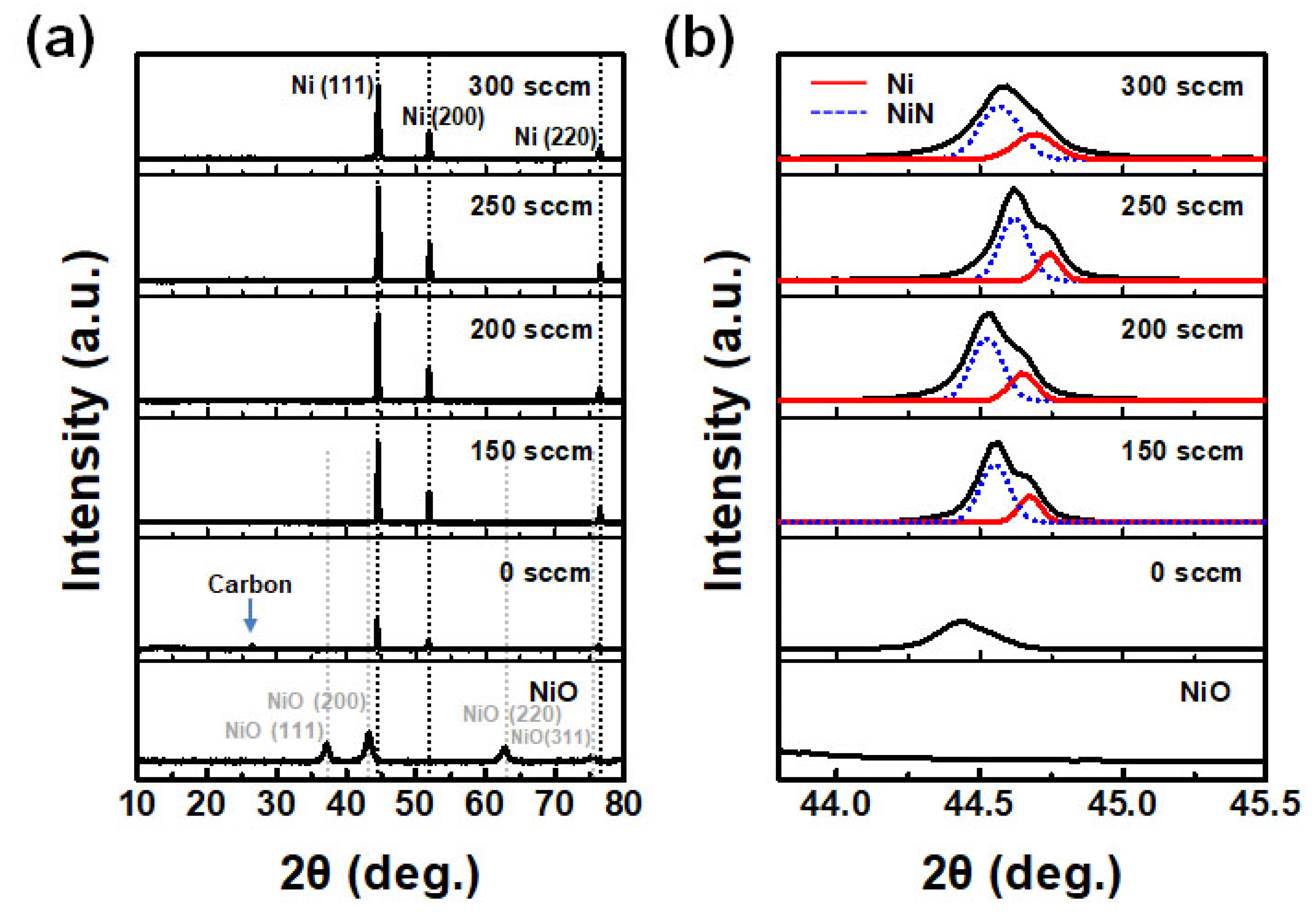
Figure 1. (a) XRD patterns of the nitrogen-doped Ni-graphene CSNPs synthesized at different NH3 flow amounts and (b) magnification and peak separation of Ni (111) peak positions in Figure 1a.
Photonics 10 00018 g001
Figure 2. (a) N 1 s XPS spectra of the nitrogen-doped Ni-graphene CSNPs, (b) peak area according to nitrogen bonding, and (c) N/C ratio for different NH3 flow amounts.
Photonics 10 00018 g002
Figure 3. (a) Raman peaks of the synthesized nitrogen-doped Ni-graphene CSNPs with different NH3 flow amounts, (b) the intensity ratio of the D- and G-bands, ID/IG, and (c) the intensity ratio of the 2D- and G-bands, I2D/IG.
Photonics 10 00018 g003
Figure 4. (a) High resolution (H-TEM) image, and (be) elemental mapping of the N-doped Ni-graphene CSNPs for an NH3 flow amount of 300 sccm.
Photonics 10 00018 g004
Figure 5. (a) Cell’s structure of Glass/ITO/PEDOT:PSS/(SnS + PBT7 + N-NiGR)/ZnO/ EGaIn and (b) the J-V curves of the cell without and with N-NiGR NPs with different of concentration (wt.%).
Photonics 10 00018 g005
Table 1. Device parameters such as PCE (power conversion efficiency), Voc (open circuit voltage), Jsc (short circuit current density), and FF (fill factor) from J–V characteristics without and with different of N-NiGR concentration under illumination at 100 mW/cm2.
Device StructureJsc
(mA/cm2)
Voc
(V)
FF
(%)
Eff
(%)
Without N-NiGR3.410.7361.701.53
With N-NiGR (0.25 mg)4.420.7367.02.12
With N-NiGR (0.5 mg)6.800.7771.23.78
With N-NiGR (0.75 mg)7.610.7772.14.35
With N-NiGR (1.00 mg)6.320.7766.43.16
Disclaimer/Publisher’s Note: The statements, opinions and data contained in all publications are solely those of the individual author(s) and contributor(s) and not of MDPI and/or the editor(s). MDPI and/or the editor(s) disclaim responsibility for any injury to people or property resulting from any ideas, methods, instructions or products referred to in the content.