Abstract
We present a novel bidirectional WDM-based optical access network featuring reconfigurable capacity assignment. The architecture relies on the PolMUX technique allowing a compact, flexible, and bandwidth-efficient router in addition to source-free ONUs and color-less ONUs for cost/complexity minimization. Moreover, the centralized architecture contemplates remote management and control of polarization. High-quality transmission of digital signals is demonstrated through different routing scenarios where all channels are dynamically assigned in both downlink and uplink directions.
1. Introduction
Nowadays, wavelength division multiplexing (WDM)-based optical access networks are considered the most promising solution in order to offer broadband access connections to a worldwide increasing number of customers since all benefits of optical fiber technology are fully exploited and capacity-per-user can be very high [1,2,3,4]. Nevertheless, issues like large bandwidth, easy upgradability and service transparency come often with high complexity and costs especially when multiple optical network units (ONUs) are deployed throughout the network.
To address these limitations, the dynamical capacity reconfiguration is an advanced strategy that provides an efficient sharing of the available bandwidth resources avoiding any waste of capacity in case of fluctuations of the traffic loads. The use of flexible wavelength routers to dynamically assign a different number of WDM channels depending on the actual ONUs demand has been previously proposed in [5,6,7,8,9]. However, in most cases, either a large and costly number of components or limitations to the ONUs upgrading may render feasibility and scalability a rather complicated and costly task.
Moreover, the polarization multiplexing (PolMUX) technique has been recently presented [10,11] as a potential candidate for future optical networks, also providing converged signals transmission over a colorless DWDM passive optical network [12]. As the authors previously demonstrated in [13], the PolMUX approach can be implemented at the central office (CO) transceiver to generate two orthogonally polarized downstream and upstream optical carriers using the same wavelength. Therefore, the PolMUX technique can be used as a light-source centralization strategy to perform the uplink transmission with source-free and color-less ONUs. As a main advantage, this technique guarantees minimal overall network complexity and fabrication costs compared to other alternatives [14,15,16,17], where bandwidth limitations, high injection powers, expensive optical devices or extra light sources may constitute a disadvantage.
In this paper, the authors propose a novel WDM optical access network combining dynamic channels assignment and polarization multiplexing (PolMUX) technique. Network reconfigurability is realized by means of a very compact and bandwidth-efficient wavelength router based on AWG and optical switching technology. In this work, the integration of the PolMUX technique into a reconfigurable network architecture will bring significant advantages since the bandwidth-per-channel required by the router for wavelength distribution between the CO and each ONU is halved. It leads to a substantial optimization of capacity resources and increases simultaneously the scalability and flexibility of the network enabling more users. Moreover, the PolMUX strategy allows an effective implementation of source-free and color-less ONUs with a functionally simple and identical structure, using a single optical fiber for both downlink and uplink transmission. Furthermore, in this contribution, we demonstrate centralized polarization management and control operations, which overcomes the major drawback of the PolMUX approach relying on the tracking and control of the polarization required at each ONU [17]. In addition, an emphasis is required on the main goal of this work, which is to demonstrate the flexibility of a capacity reconfigurable full-duplex transmission system using the PolMUX technique. This goal has been successfully accomplished by using moderate transmission rates compared with previous reports as [4] or [10], due to limitations on the available equipment for signal generation, but without loss of generality. In our system, optical channels are transparent to modulation format and transmission rate up to the modulator bandwidth so performance characterization is directly extensible to 40 Gb/s per channel.
This paper is structured as follows. Section 2 provides a detailed description of the full-duplex reconfigurable PolMUX-based optical access network. The integration of the PolMUX technique into the reconfigurable node is demonstrated through different wavelength routing scenarios where all WDM PolMUX channels are dynamically allocated by the router depending on the ONU demand. In Section 3, the transmission performance of the network is tested by distributing SCM digital signals [17,18,19] and propagated over 10 km of single mode fiber (SMF). Finally, the main conclusions are summarized in Section 4.
2. Network Architecture
2.1. Description
Figure 1 illustrates the block diagram of the proposed WDM optical access network with dynamic and bidirectional capacity assignment based on the PolMUX principle. According to a conventional passive optical network (PON) topology, the principal blocks of the network architecture are the central office (CO), the optical link, the remote node (RN) and a group of optical network units (ONUs) remotely located.
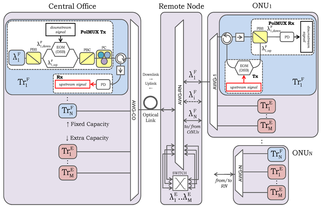
Figure 1.
Full-duplex reconfigurable PolMUX-based WDM optical access network.
Figure 1.
Full-duplex reconfigurable PolMUX-based WDM optical access network.
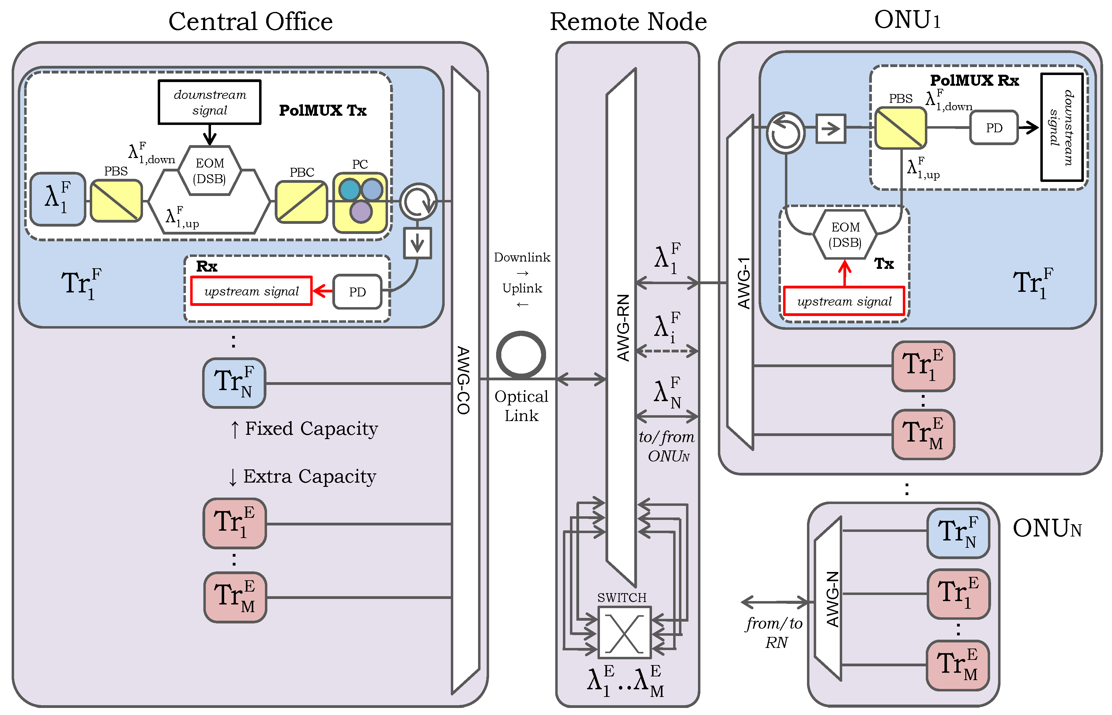
The CO contains a set of optical transceivers. A number N of them (from Tr1F to TrNF) is reserved to the fixed capacity channels assignment whereas a number M of them (from Tr1E to TrME) is reserved to the extra capacity channels assignment. The architecture of all transceivers is identical. Each transceiver is composed by a PolMUX transmitter (PolMUX Tx) and a simple receiver (Rx) structure. In the PolMUX Tx, a single optical source provides an optical wavelength λ1F carrier which is split in two signals by a polarization beam splitter (PBS). In such a way, two orthogonally polarized optical fields are generated at the same wavelength. One of them, λF1,down is chosen as the optical downlink carrier and, thus, it is externally modulated by the downstream signal using an electro-optical modulator (EOM). The other carrier, λF1,up is left as a continuous wave (CW) and takes the role of uplink carrier. Both optical carriers are multiplexed into a polarization beam combiner (PBC) and injected into the network. Therefore, in the CO, a number (M+N) transceivers provide a pair of optical PolMUX carriers for the downlink and uplink transmission.
Every pair of PolMUX carriers at the output of its correspondent transceiver are multiplexed by means of a [N+M]In × [1]Out Arrayed Waveguide Grating (AWG-CO) wavelength multiplexer/demultiplexer. Thus, all combined fixed and extra wavelengths are propagated in downlink direction through the optical fiber link.
The RN is based on a very compact and flexible wavelength router based on a cyclic [N+M]In × [N+M]Out AWG where N and M are the number of fixed and extra capacity channels respectively [6]. The network capacity is dynamically reconfigured in both downlink and uplink directions by means of an [M]In × [N+M-1]Out optical switch, being M the number of extra capacity channels.
In the downlink direction, the AWG-RN performs a demultiplexing operation feeding each ONU with its correspondent set of PolMUX wavelengths. Symmetrically, in uplink direction, the AWG-RN multiplexes and forwards the uplink wavelengths from each ONU back to the CO. A number of N ports of the AWG-RN are always used to provide the bidirectional routing of the N wavelengths. In this way a fixed unitary capacity assignment is assured for each ONU. In addition, depending on the actual service demand, all ONUs are allowed to increase their total bandwidth by a number of extra channels. In fact, when extra capacity is required, the reconfiguration state of the optical switch can be varied dynamically in order to enable a maximum number of M ports of the AWG-RN and, thus, supply the M extra capacity wavelengths. The extra wavelengths are launched back from the optical switch to the input ports of the AWG-RN and emerge from the output ports assigned to the demanding ONU. Thanks to the PolMUX approach, each pair of downlink and uplink carriers fills the same spectral portion. In turns, the spectral efficiency of the AWG-RN is doubled. Therefore, the spectral characteristics of the RN described above are better exploited than the one of the remote routers proposed in [5,6,7,8,9].
In the system depicted in Figure 1, all ONUs are identically composed by an optical AWG and a set of (M+1) optical transceivers structured in two principal parts: the PolMUX receiver (PolMUX Rx) and the transmitter (Tx). The first ONU transceiver is reserved to the associated fixed capacity wavelength, λ1F. Here, operations such as the photodetection and demodulation of the downlink carrier, λF1,down as well as the modulation and back-propagation of the uplink wavelength, λF1,up are realized once the two optical PolMUX carriers have been separated by the PBS. The remaining M transceivers perform the same operations but with the extra capacity wavelengths. The (M+1) channels are multiplexed back through a [1]In × [M+1]Out AWGi located at ONU i. Note that, the maximum number of ONUs deployed in the network agrees exactly with the number of fixed capacity wavelengths supplied by the CO, which is N. Owing to the integration of the PolMUX scheme into the network, all ONUs present an identical architecture where all receiving and transmitting operations are performed with a minimized number of components in a way perfectly compatible with the reconfigurable architecture of the network. We remark also the main advantage brought by the integration of the PolMUX strategy into the network, which is the fact that all ONUs keep source-free, while the CO centralizes and provides all downlink and uplink carriers.
Furthermore, in the proposed network configuration, the tracking and control of polarization is also centralized, as a main difference to the previous proposal in [6]. The device employed to perform such polarization tracking and control is the automatic polarization controller (PC) which is now inserted into each CO transceiver rather than its correspondent ONU. Experimentally, the functionality of the PC is to set a certain polarization extinction ratio (PER) between the two PolMUX carriers and to keep the maximum degree of orthogonality between them during the propagation. This condition is mandatory for the success of the PolMUX technique and must be verified just when the two PolMUX carriers are finally separated at the ONU.
In [6] it was demonstrated that when the PER is kept to levels higher than 30 dB, the quality of downstream and upstream demodulated signals is widely acceptable. Based on the last assertion, a logical position of the PC would be the ONU. However, the location of the PC can be moved from the ONU to the CO without modifying the transmission performances of the PolMUX system. It is based on the following consideration. When the PC is located at the CO, it is capable of setting the required PER between the PolMUX carriers combined before the downlink propagation. Besides this operation, the PC can be also used to supervise and, in case of polarization misalignments, rectify the state of polarization (SoP) of the uplink optical carrier received after the round trip. In fact, once the upstream signal is received at the CO, its quality can be always taken as “feedback” information about the degree of orthogonality of the two PolMUX carriers received remotely at the ONU.
This assumption is supported by the fact that the PolMUX scheme generates two optical carriers in orthogonal SoP at the CO. In other words, a good/bad quality of the upstream signal demodulated at the CO means automatically that also the downstream signal has been demodulated correctly/incorrectly at the ONU. Under this condition, each of the two positions of the PC are conceptually equivalent since the orthogonality between the PolMUX carriers can be always monitored and maintained either locally at the ONU or remotely at the CO taking the SoP of the uplink carrier as reference.
However, the location of the PC is very critical from a practical point of view. Indeed, the insertion of a PC increases the complexity and cost of each ONU and constrains the operator to locally perform the monitoring and control of the polarization as well as all the operations required in case of polarization misalignments, which is a significant drawback in optical access networks where multiple ONUs are deployed. In contrast, the installation of all PCs at the CO avoids inventory and management issues at the ONU favoring the practical implementation of the network.
2.2. Wavelengths Plan and Characteristics of the Routing Components
In order to provide an experimental validation, the proposed network architecture in Figure 1 has been implemented using a number of 4 and 2 fixed and extra capacity wavelengths, respectively. The four fixed wavelengths identified as λ1F, λ2F, λ3F and λ4F and the two extra wavelengths, λ2E and λ2E are all emitted by a ITU 0.8 nm-spacing WDM grid multi-wavelength optical source operating in the third transmission window. The AWGs employed in the CO and in each of the four ONUs are [40]In × [1]Out and [1]In × [40]Out respectively with a larger number of ports than required for availability reasons. The AWG-RN is a cyclic [18]In × [18]Out AWG. All AWGs are thermally controlled for matching and stabilization into the ITU grid. Since in our experimental setup M + N = 6, the AWG-RN widely satisfies the number of input and output ports required, with high capacity to accommodate new more channels. The optical switch is a [8]In × [8]Out prism switch providing channel selection between a pair of input and output fibers with ultra-low insertion loss. Finally, the transmission is run over 10 km of SMF.
Figure 2 shows the wavelength plan measured at the AWG-CO output ports for fixed and extra capacity channels. The first four ports of the AWG-RN are assigned to the fixed capacity wavelengths between the CO and ONUs 1 to 4. The last two ports, 17 and 18, are reserved to route the extra wavelengths λ2E and λ1E respectively. Note that, the accommodation of the extra wavelengths keeps available the central part of the AWG-RN spectral grid for further addition of new wavelengths. This approach shows the great flexibility and scalability of the network to manage higher number of ONUs and/or higher reconfiguration capacity.
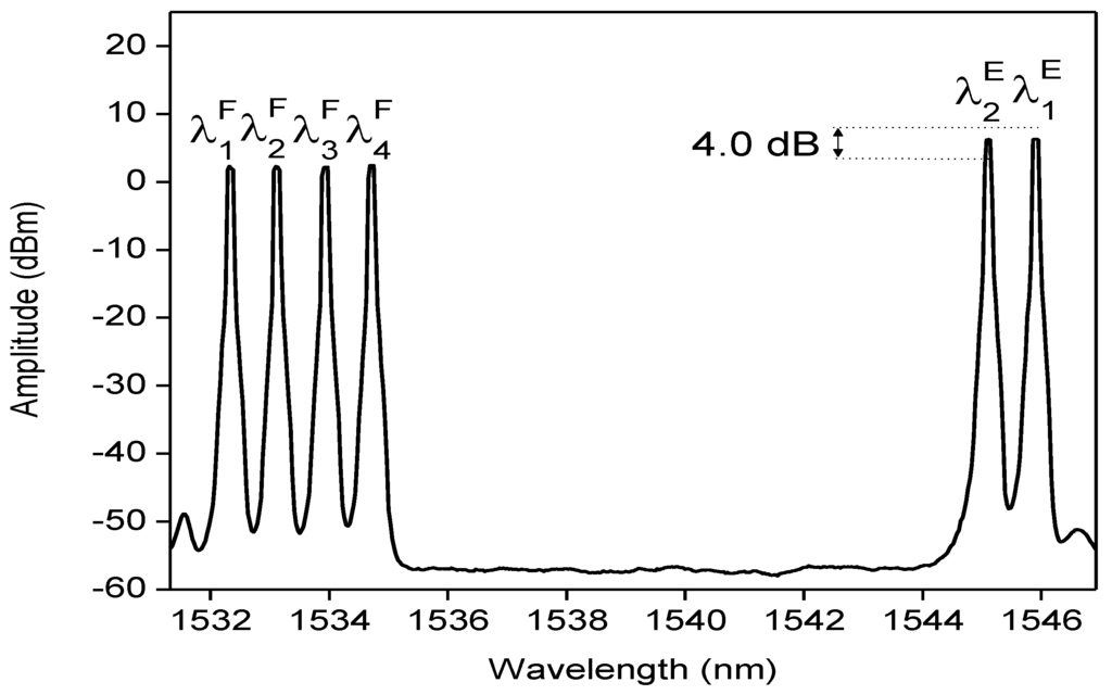
Figure 2.
Wavelength spectrum measured at the output of the AWG-CO.
Figure 2.
Wavelength spectrum measured at the output of the AWG-CO.
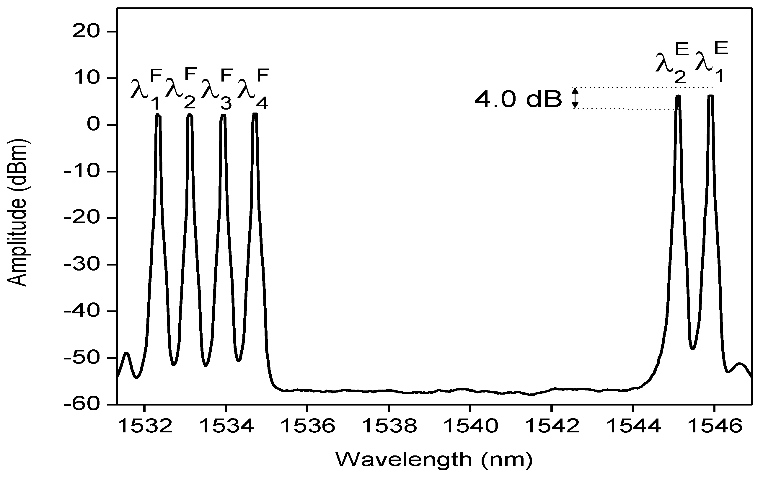
The optical input power of the extra capacity channels was set 4 dB higher than the optical input power of the fixed channels in order to pre-compensate the insertion loss of the AWG-RN (≈3.5 dB) and the optical switch (≈0.5 dB). In this way, the optical power of both fixed and extra wavelengths in the receiver are roughly the same, allowing a better comparison between them and a more realistic evaluation of the network performance. The optical losses undergone by all wavelengths at the AWG-CO output are around 7 dB, as shown in Figure 2, mainly due to the AWG-CO and the polarization components in the CO.
2.3. Definition of the Routing Scenarios
As previously explained, apart from the fixed channel assignment, the router described in Figure 1 is capable to dynamically provide a number of extra channels. Experimentally, such traffic reconfiguration can be implemented and evaluated through different routing scenarios where extra service demand from one or more ONUs implies that one or more extra channels must be routed to them. Taking into account the wavelength plan of Figure 2, and, with no loss of generality, we have implemented two different routing scenarios whose schematic representation is given in Table 1.
In the first scenario the extra wavelengths, λ1E and λ2E, are assigned to ONU3, emulating the case of maximum capacity demand from one single ONU. In the second scenario λ1E is assigned to ONU1 whereas λ2E is routed to ONU2. The second scenario is a clear example of network resource-sharing between two different ONUs. In both scenarios, a fixed capacity service is always assured by routing all fixed wavelengths to their corresponding ONUs. The optical spectra measured at the input of each ONU are given in Figure 3 for (a) scenario 1 and (b) scenario 2, respectively.

Table 1.
Experimental routing scenarios.
| Scenario 1 | Scenario 2 | |||||||||||
|---|---|---|---|---|---|---|---|---|---|---|---|---|
| Fixed λs | Extra λs | Fixed λs | Extra λs | |||||||||
| ONU1 | ||||||||||||
| ONU2 | ||||||||||||
| ONU3 | ||||||||||||
| ONU4 | ||||||||||||
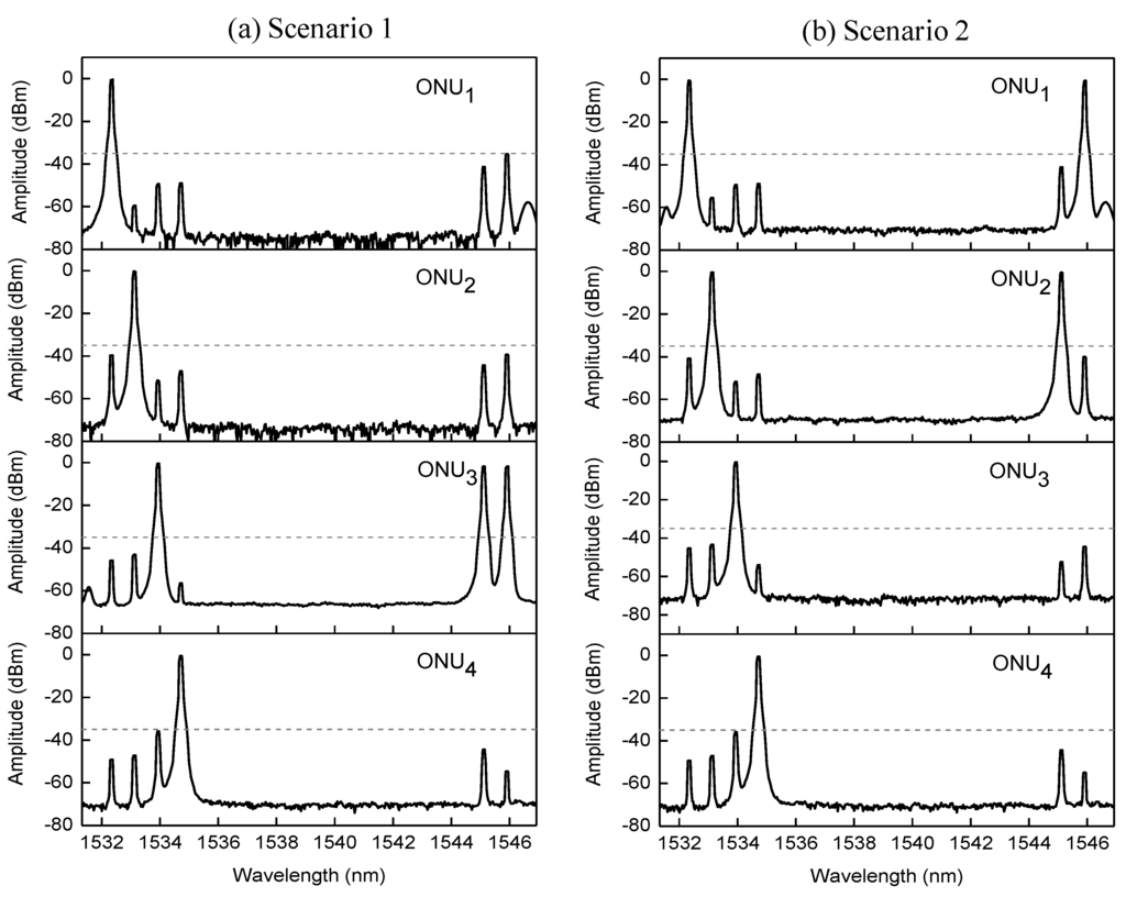
Figure 3.
Optical spectra measured at the AWG-RN outputs in downlink direction for (a) scenario 1; (b) scenario 2.
Figure 3.
Optical spectra measured at the AWG-RN outputs in downlink direction for (a) scenario 1; (b) scenario 2.
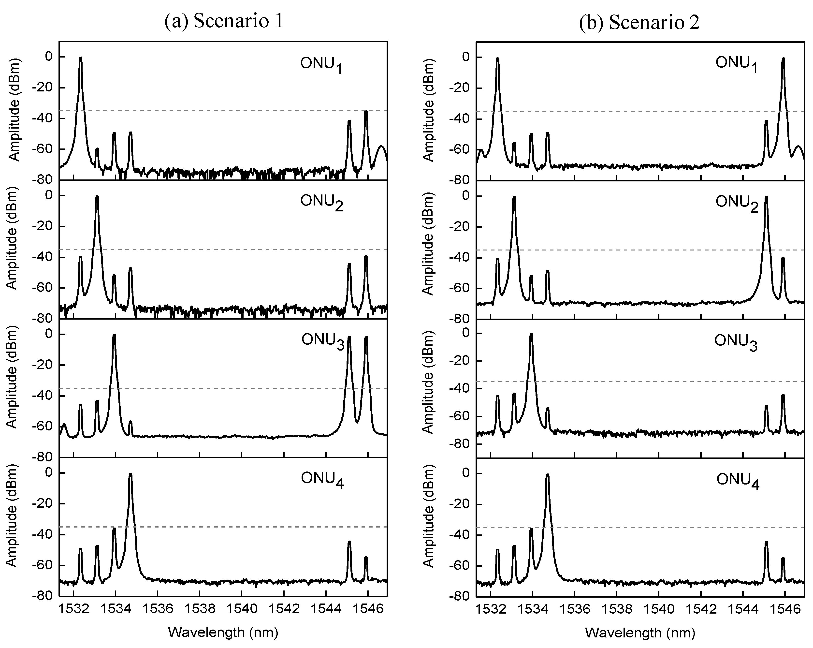
In Figure 3a the two extra wavelengths are both routed to ONU3 and they emerge from the AWG-RN with the same optical amplitude level than the fixed wavelengths due to the optical power precompensation explained above. Note that the amplitude level of all the three wavelengths present in this ONU is reduced by an amount of 3.5 dB with respect to the level in Figure 2, due to the AWG-RN loss. In Figure 3b the extra wavelength λ1E is received by ONU1 while the extra wavelength λ2E is routed to the adjacent ONU2 according to the second scenario. Again, all fixed and extra wavelengths show equalized optical power and losses due to the AWG-RN.
Independently of the scenario, it can be also observed that each ONU, apart from the corresponding set of wavelengths, receives also a small amount of optical power from other adjacent channels. This power leakage is due to the unavoidable inter-channel crosstalk at the AWG-RN and, depending on the filtering characteristics of the AWG-RN, it may vary from band to band. However, the crosstalk level is kept always higher than 35 dB (see dashed line of Figure 3) and does not affect significantly the routing operations.
3. Experimental Evaluation of Network Performance
We have tested the full-duplex and simultaneous transmission of all fixed and extra channels over 10 km of SMF. The optical switch has been configured according to the two scenarios defined above. The orthogonality between all PolMUX carriers in terms of PER has been set to 30 dB by means of all PCs installed at the CO. The PER is defined as the difference in dB between the maximum amplitudes of the PolMUX carriers. The down- and upstream traffic is provided by an electrical vector signal generator implementing the SCM scheme. We have established a maximum 10% error vector magnitude (EVM) criterion.
3.1. Degradation of Fixed and Extra Capacity Channels
In the experimental setup each fixed wavelength transports 5 Mb/s QPSK data modulating its own 10 GHz electrical subcarrier. To differentiate the fixed service from the extra service, each extra capacity channel transports 10 Mb/s 64- QAM data modulating its own 5 GHz electrical subcarrier.
Figure 4 plots the downlink EVM (a) and the uplink EVM (b) as a function of the received electrical power for the fixed channel assignment in both scenarios, also showing the optical back to back.
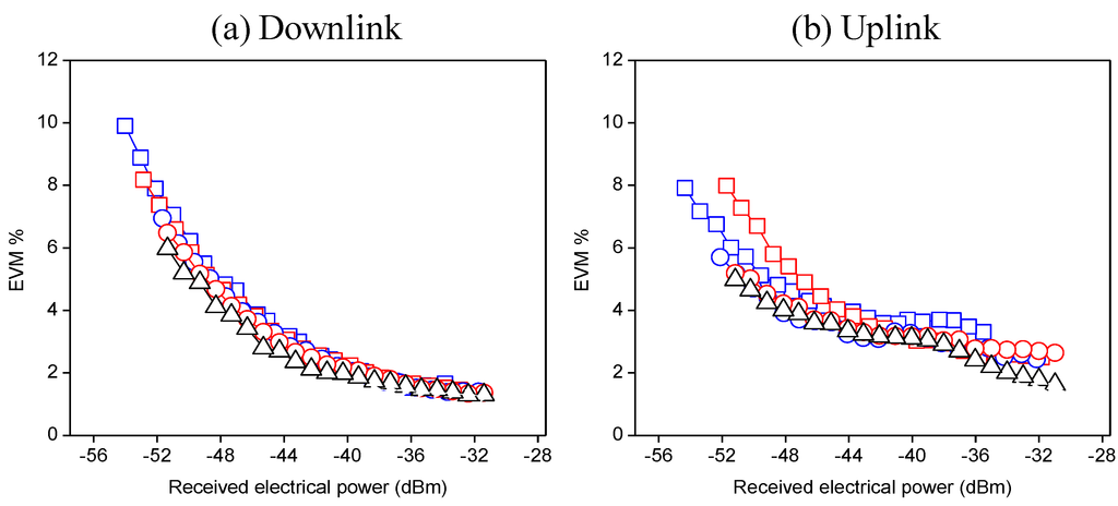
Figure 4.
EVM vs. received electrical power for fixed channels. [Scenario 1 (  ) and 2 (
  )]. [Scenario 1 (
  ) and 2 (
  )].Optical back-to-back (∆). (a) Downlink and (b) uplink propagation.
 ) and 2 (
  )]. [Scenario 1 (
  ) and 2 (
  )].Optical back-to-back (∆). (a) Downlink and (b) uplink propagation.
Figure 4.
EVM vs. received electrical power for fixed channels. [Scenario 1 (  ) and 2 (
  )]. [Scenario 1 (
  ) and 2 (
  )].Optical back-to-back (∆). (a) Downlink and (b) uplink propagation.
 ) and 2 (
  )]. [Scenario 1 (
  ) and 2 (
  )].Optical back-to-back (∆). (a) Downlink and (b) uplink propagation.
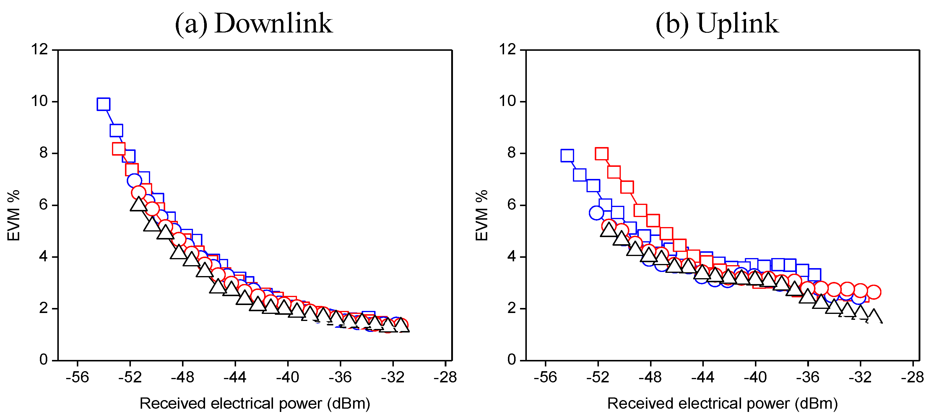
Figure 4a shows an expected improvement of the received signal quality with the received electrical power. In a range of 20 dBm and, independently of the scenario, the EVM reached at ONU1 and ONU3 goes from minimum values of 1.4% up to maximum values not exceeding 10%.
Therefore, both ONUs demodulate their respective downstream signals with an acceptable quality which becomes especially high for electrical powers higher than −37 dBm. Comparing the same channel in the two scenarios, we observe small EVM fluctuations due to a different amount of crosstalk induced by the adjacent channels. On the other hand, the fluctuations between channel 1 and 3 are due to the power distribution of the AWG employed in the RN which depends on the specific band, and also to small differences between the AWGs employed in ONU1 and ONU3 regarding their optical power distribution. The results obtained are very close to the back-to-back curve and become practically indistinguishable, especially when the received power increases.
Analogous considerations can be made for the results of the uplink transmission shown in Figure 4b. Again, at the CO transceiver, the quality of the demodulated signals carried by channel 1 and 3 improves with the electrical power and never exceeds the maximum EVM criterion. Note that, although not included in the plots for the sake of simplicity, similar results have been measured also for the signals carried by wavelengths λ2F and λ4F.
The quality of those signals carried by the extra channels λ1E and λ2E has been also evaluated. Figure 5a,b show the downlink and uplink EVM degradation of these extra services, respectively.
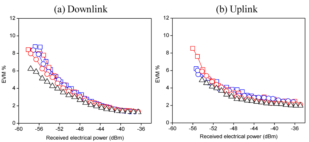
Figure 5.
EVM vs. received electrical power for extra capacity wavelengths. λ1E [Scenario 1 (  ) and 2(
  )]. λE [Scenario 1(
  ) and 2(
  )].Optical back-to-back (∆). (a) Downlink and (b) uplink propagation.
 ) and 2(
  )]. λE [Scenario 1(
  ) and 2(
  )].Optical back-to-back (∆). (a) Downlink and (b) uplink propagation.
Figure 5.
EVM vs. received electrical power for extra capacity wavelengths. λ1E [Scenario 1 (  ) and 2(
  )]. λE [Scenario 1(
  ) and 2(
  )].Optical back-to-back (∆). (a) Downlink and (b) uplink propagation.
 ) and 2(
  )]. λE [Scenario 1(
  ) and 2(
  )].Optical back-to-back (∆). (a) Downlink and (b) uplink propagation.
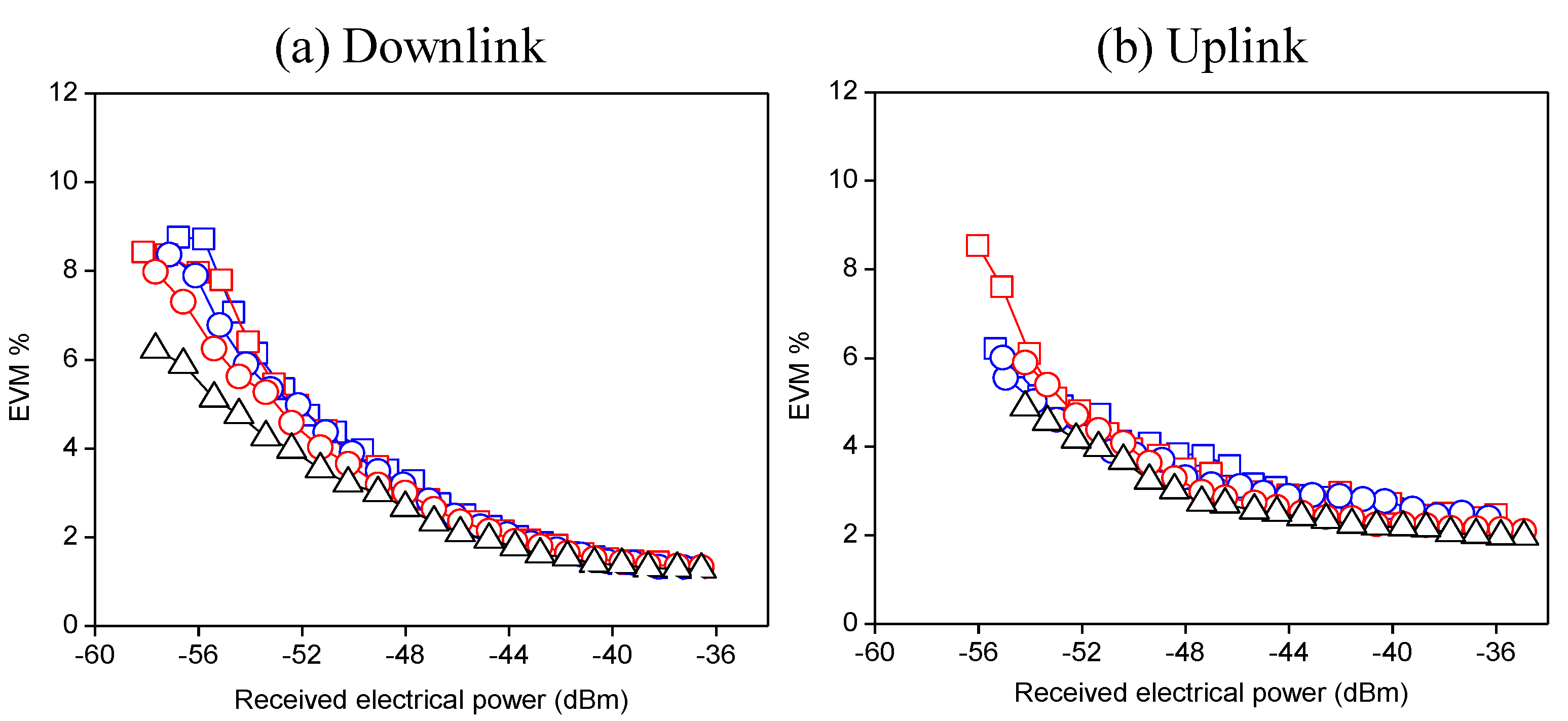
As in the previous case, Figure 5a shows minimum EVM’s around 1.3% and maximum EVM not higher than 8% in a power range of 20 dBm. This result is independent of the scenario especially when the received power is higher than −38 dBm where all curves overlap each others. We remark that the extra capacity channels do not affect each other neither when they are routed to the same ONU (scenario 1) nor when they are routed to adjacent ONUs (scenario 2). It is also notable the fact that even in case of using extra capacity wavelengths in the network, all curves are very close to the back-to-back one showing a negligible degradation introduced by the proposed system also when services are dynamically assigned. Figure 5b shows very similar EVM measurements for the uplink transmitted signals. Therefore, according to experimental results shown in Figure 4 and Figure 5, the network performances do not vary significantly with respect to a fixed capacity routing when extra capacity is assigned to one or more ONUs.
3.2. Impact of the Electrical Subcarrier Frequency
In this subsection, the network performance has been analyzed in terms of the electrical subcarrier frequency in order to validate the adaptability of the network in SCM schemes to an increase of the spectral efficiency.
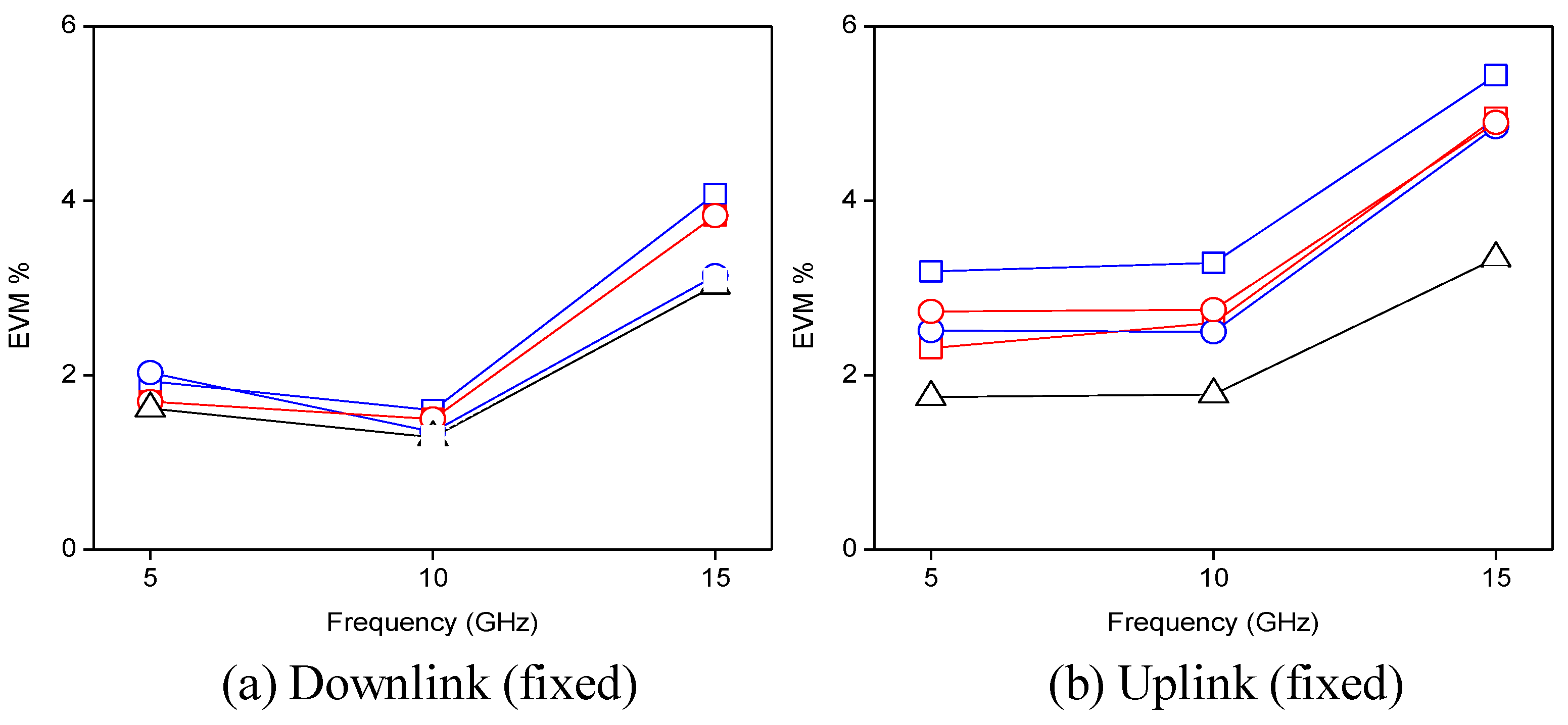
Figure 6 plots the downlink (a) and the uplink (b) EVM measurements as a function of the electrical subcarrier frequency for an input electrical power of 12 dBm which has been set as reference level to achieve an acceptable photodetected power.
Although all fixed wavelengths have been transmitted and measured in the actual test, to avoid redundancy of information we show only the results related to the fixed capacity distribution of wavelengths λ1F and λ3F. In particular, the EVM curves refer to the degradation of digital signals carried by λ1F in both scenarios including the back-to-back curve. In this test each fixed wavelength transports 5 Mb/s QPSK data modulated onto different subcarrier frequency while the extra capacity channels λ1E and λ2E transport 10 Mb/s 64-QAM data modulating subcarriers set to a fixed value of 5 GHz.
Figure 6 shows EVM fluctuations around 2% and 3% for the two subcarriers, 5 GHz and 10 GHz, onto channels 1 and 3 independently on the implemented scenario. At the highest subcarrier frequency under test, 15 GHz, the EVM worsens to 3.1%–4.0% and 4.8%–5.4% in the downlink and uplink directions, respectively. This EVM increase is due to the EOMs bandwidth. However, even in the worst case, the EVM is always largely below 10%. It demonstrates the versatility of the network to support the SCM scheme.
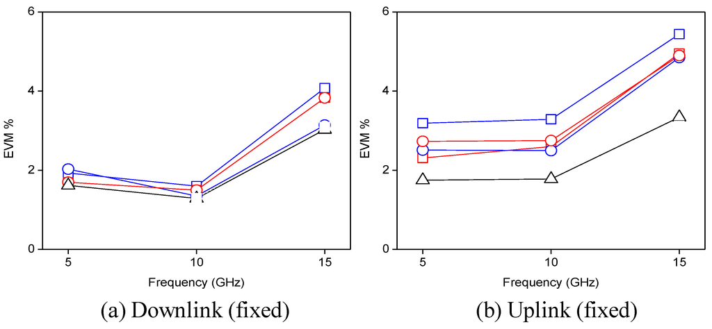
Figure 6.
EVM vs. SCM frequency for (a) downlink and (b) uplink transmission in different routing scenarios considering fixed channels λ1F [scenario 1 (  ) and 2 (
  )] and λ3F [scenario 1 (
  ) and 2 (
  )]. Optical back-to-back (∆). Note: both extra capacity wavelengths λ1E and λ2E carry 10 Mb/s 64-QAM data over 5 GHz SCM tones.
 ) and 2 (
  )] and λ3F [scenario 1 (
  ) and 2 (
  )]. Optical back-to-back (∆). Note: both extra capacity wavelengths λ1E and λ2E carry 10 Mb/s 64-QAM data over 5 GHz SCM tones.
Figure 6.
EVM vs. SCM frequency for (a) downlink and (b) uplink transmission in different routing scenarios considering fixed channels λ1F [scenario 1 (  ) and 2 (
  )] and λ3F [scenario 1 (
  ) and 2 (
  )]. Optical back-to-back (∆). Note: both extra capacity wavelengths λ1E and λ2E carry 10 Mb/s 64-QAM data over 5 GHz SCM tones.
 ) and 2 (
  )] and λ3F [scenario 1 (
  ) and 2 (
  )]. Optical back-to-back (∆). Note: both extra capacity wavelengths λ1E and λ2E carry 10 Mb/s 64-QAM data over 5 GHz SCM tones.
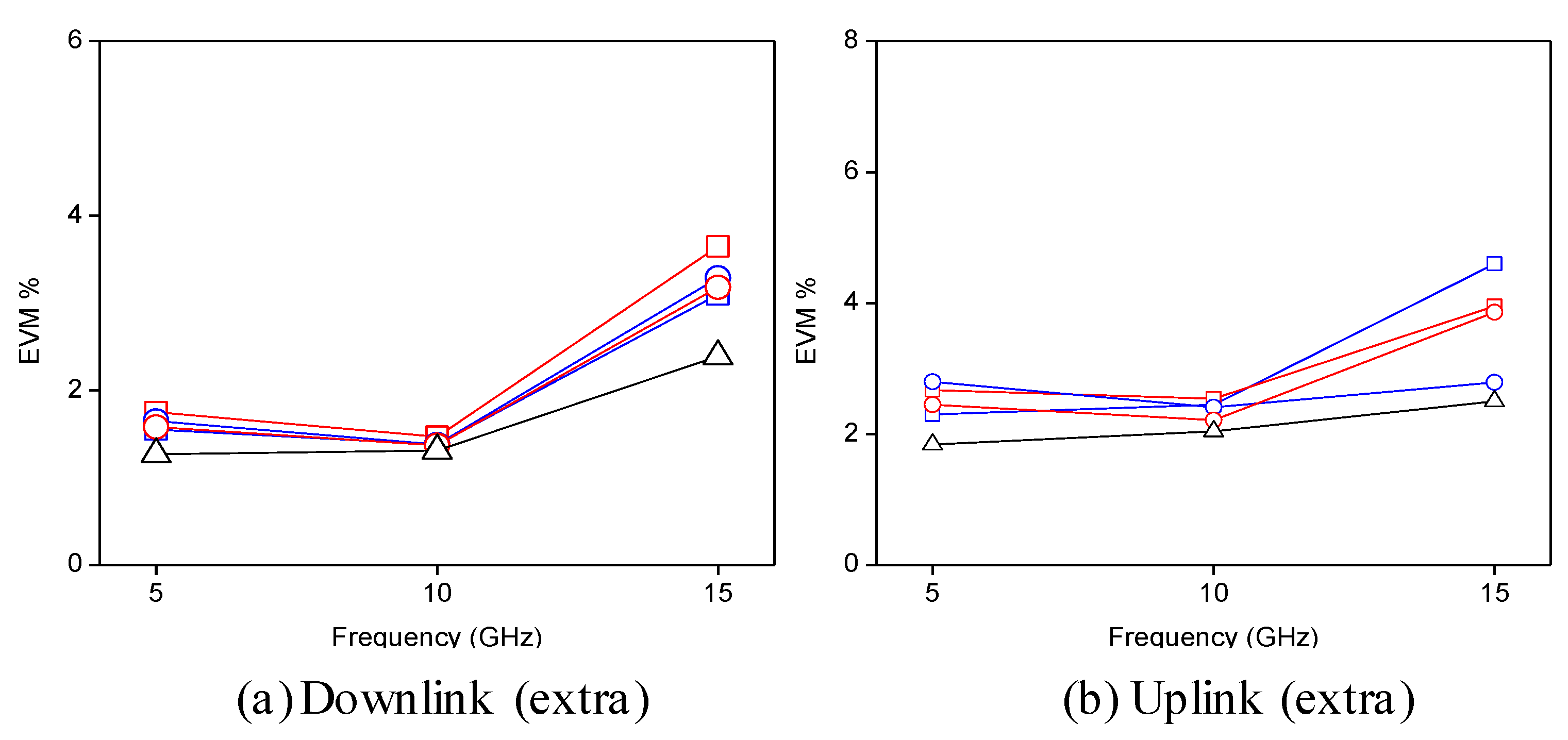
With regard to the extra services demand, Figure 7a,b show the experimental results measured for extra wavelengths λ1E and λ2E. In this second test, both extra channels are carrying 10 Mb/s 64-QAM data modulating electrical subcarriers at the corresponding frequency while all the fixed wavelengths are carrying 5 Mb/s QPSK data modulated onto SCM tones set to a fixed value of 10 GHz.
Similarly to Figure 6, the EVM values never exceeded the maximum established level. Therefore we conclude that the signal quality under variable network capacity assignment is transparent to the electrical subcarrier frequency.
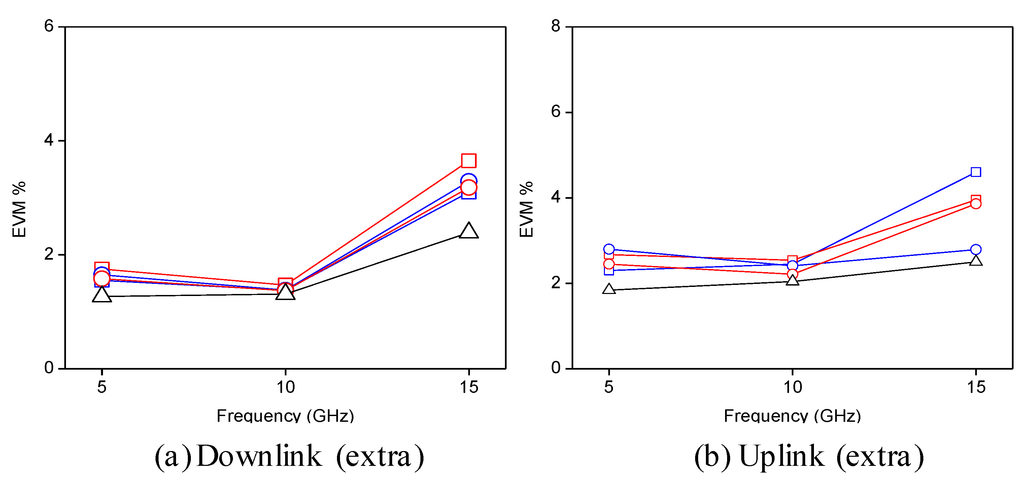
Figure 7.
EVM vs. SCM frequency for (a) downlink and (b) uplink transmission in different routing scenarios considering extra channels λ1E [scenario 1 (  ) and 2 (
  )] and λ2E [scenario 1 (
  ) and 2 (
  )]. Optical back-to-back (∆). Note: all fixed capacity wavelengths carry 5 Mb/s QPSK data over 10 GHz SCM tones.
 ) and 2 (
  )] and λ2E [scenario 1 (
  ) and 2 (
  )]. Optical back-to-back (∆). Note: all fixed capacity wavelengths carry 5 Mb/s QPSK data over 10 GHz SCM tones.
Figure 7.
EVM vs. SCM frequency for (a) downlink and (b) uplink transmission in different routing scenarios considering extra channels λ1E [scenario 1 (  ) and 2 (
  )] and λ2E [scenario 1 (
  ) and 2 (
  )]. Optical back-to-back (∆). Note: all fixed capacity wavelengths carry 5 Mb/s QPSK data over 10 GHz SCM tones.
 ) and 2 (
  )] and λ2E [scenario 1 (
  ) and 2 (
  )]. Optical back-to-back (∆). Note: all fixed capacity wavelengths carry 5 Mb/s QPSK data over 10 GHz SCM tones.
4. Conclusions
In this paper, we have proposed and experimentally demonstrated a full-duplex reconfigurable WDM optical access network integrating the optical PolMUX technique. The PolMUX scheme uses light polarization as a degree of freedom to multiplex into the same channel the optical downlink and uplink carriers provided by a single optical source. This principle brings multiple advantages when integrated into a reconfigurable network environment. The PolMUX scheme allows the centralization of the entire wavelengths provisioning, polarization tracking and control at the central office. As the experimental results shows, the systems provides a high stability for both up and downlink. The key for the stability remains in the proposed centralized architecture which permits the remote management and control of polarization form the CO. Note that the main disadvantage in conventional systems is the requirement of automatic PC for each ONU, which is expensive and not really reliable in practical when high capacity is required. Keeping the ONUs color-less, source-free and polarization independent reduces considerably both the network complexity and cost at the same time. In these conditions, scalability and wavelength upgrading can be implemented by means of adding new light-sources at the CO without significant changes in the network infrastructure and especially in the RN and ONU architectures. Moreover, we have demonstrated that the PolMUX scheme is highly compatible with all routing operations performed for both fixed and reconfigurable capacity assignment. The PolMUX scheme allows the RN to be spectral efficient with no waste of bandwidth. The evaluation of network performance has been carried out considering the full-duplex transmission of different services through different routing scenarios where extra capacity wavelengths have been assigned dynamically to different ONUs according to the actual demand. In all cases the EVM of the demodulated channels always verifies the conventional requirements independently of the scenario and direction of propagation. We have also demonstrated that the network is also compatible with the SCM technique in the electrical domain since the signal quality is almost transparent to variations of the electrical subcarrier frequency apart from bandwidth limitations of the experimental equipment. In this way, the spectral efficiency of the network can be further increased with a substantial improvement of the network flexibility.
Acknowledgments
This work was supported by the national project TEC2011-26642 funded by the Ministerio de Economía y Competitividad. Also, The authors wish to acknowledge the financial support given by the Generalitat Valenciana under the Research Excellency Award Program GVA PROMETEO 2013/012 Next Generation Microwave Photonic technologies.
Author Contributions
Our work is a product of the intellectual environment of the whole team, all members have contributed in various degrees to the research concept, and to the experiment design: JM and BO worked on the conception and design of the study, JM performed a great part of the analysis and interpretation of data, FG contributed to the design of the study and the acquisition of data and all authors participated in drafting the article and revising it critically for important intellectual content.
Conflict of Interest
The authors declare no conflict of interest.
References
- Banerjee, A.; Park, Y.; Clarke, F.; Song, H.; Yang, S.; Kramer, G.; Kim, K.; Mukherjee, B. Wavelength-division-multiplexed passive optical network (WDM PON) technologies for broadband access: A review. J. Opt. Netw. 2005, 4, 737–758. [Google Scholar] [CrossRef]
- Lee, C.; Sorin, W.V.; Kim, B.Y. Fiber to the Home Using a PON Infrastructure. IEEE J. Lightwave Technol. 2006, 24, 4568–4583. [Google Scholar] [CrossRef]
- Kazovsky, L.G.; Shaw, W.-T.; Gutierrez, D.; Cheng, N.; Wong, S.-W. Next-Generation Optical Access Networks. IEEE J. Lightwave Technol. 2007, 25, 3428–3442. [Google Scholar]
- Guo, Q.; Tran, A.V. Wavelength-reused WDM access network supporting 40 Gb/s downlink and 10 Gb/s uplink. In Proceedings of the Optical Fiber Communication Conference (OFC) 2013, Anaheim, CA, USA, 17–21 March 2013. paper NTh4F.2.
- Hsueh, Y.; Rogge, M.S.; Yamamoto, S.; Kazovsky, L.G. A Highly Flexible and Efficient Passive Optical Network Employing Dynamic Wavelength Allocation. IEEE J. Lightwave Technol. 2005, 23, 277–286. [Google Scholar] [CrossRef]
- Ortega, B.; Mora, J.; Puerto, G.; Capmany, J. Symmetric reconfigurable capacity assignment in a bidirectional DWDM access network. Opt. Express 2007, 15, 16781–16786. [Google Scholar] [CrossRef]
- Urban, P.J.; Huiszoon, B.; Roy, R.; de Laat, M.M.; Huijskens, F.M.; Klein, E.J.; Khoe, G.D.; Koonen, A.M.J.; de Waardt, H. High-Bit-Rate Dynamically Reconfigurable WDM-TDM access network. J. Opt. Commun. Netw. 2009, 1, A143–A159. [Google Scholar] [CrossRef]
- Schrenk, B.; Lazaro, J.A.; Polo, V.; Prat, J. Multi-operability in WDM-PONs with electrically reconfigurable RSOA-Based optical network units. In Proceedings of the Access Networks and In-house Communications (ANIC) 2010, Karlsruhe, Germany, 21–24 June 2010. paper ATuB4.
- Tran, N.; Tangdiongga, E.; Okonkwo, C.; Jung, H-D.; Koonen, T. Flexibility Level Adjustment in Reconfigurable WDM-TDM Optical Access Networks. IEEE J. Lightwave Technol. 2012, 30, 2542–2550. [Google Scholar]
- Sleiffer, V.; van den Borne, D.; Veljanovski, V.; Kuschnerov, M.; Hirano, M.; Yamamoto, Y.; Takashi, J.; Sander, L.; de Waardt, H. Transmission of 448-Gb/s dual-carrier POLMUX-16QAM over 1230 km with 5 flexi-grid ROADM passes. In Proceedings of the 2012 and the National Fiber Optic Engineers Conference Optical Fiber Communication Conference (OFC), Los Angeles, CA, USA, 4–8 March 2012. paper OW4C.3.
- Chen, Z.; Yan, L.; Pan, W.; Luo, B.; Guo, Y.; Jiang, H.; Yi, A.; Sun, Y.; Wu, X. Transmission of multi-polarization-multiplexed signals: Another freedom to explore? Opt. Express 2013, 21, 11590–11605. [Google Scholar] [CrossRef]
- Shao, T.; Yao, J. Millimeter-Wave and UWB over a Colorless WDM-PON Based on Polarization Multiplexing Using a Polarization Modulator. IEEE J. Lightwave Technol. 2013, 31, 2742–2751. [Google Scholar] [CrossRef]
- Grassi, F.; Mora, J.; Ortega, B.; Capmany, J. Centralized light-source optical access network based on polarization multiplexing. Opt. Express 2010, 18, 4250–4245. [Google Scholar]
- Jia, Z.; Yu, J.; Ellinas, G.; Chang, G. Key Enabling Technologies for Optical–Wireless Networks: Optical Millimeter-Wave Generation, Wavelength Reuse, and Architecture. IEEE J. Lightwave Technol. 2007, 25, 3542–3471. [Google Scholar] [CrossRef]
- Zhang, F.; Fu, S.; Wu, J.; Xu, K.; Lin, J.; Shum, P. A Wavelength-Division-Multiplexed Passive Optical Network with Simultaneous Centralized Light Source and Broadcast Capability. IEEE Photon. J. 2010, 2, 445–453. [Google Scholar] [CrossRef]
- Schrenk, B.; Bonada, F.; Lazaro, J.A.; Prat, J. Remotely Pumped Long-Reach Hybrid PON with Wavelength Reuse in RSOA-Based ONUs. IEEE J. Lightwave Technol. 2011, 29, 635–641. [Google Scholar] [CrossRef]
- Yao, J.; Cui, W.; Tong, S. Wavelength Reuse in a UWB Over WDM-PON Based on Injection Locking of a Fabry–Pérot Laser Diode and Polarization Multiplexing. IEEE J. Lightwave Technol. 2014, 32, 220–227. [Google Scholar] [CrossRef]
- Woodward, S.L.; Phillips, M.R. Optimizing Subcarrier-Multiplexed WDM Transmission Links. IEEE J. Lightwave Technol. 2004, 22, 773–778. [Google Scholar] [CrossRef]
- Buset, J.M.; El-Sahn, Z.A.; Plant, D.V. Experimental Demonstration of a 10 Gb/s Subcarrier Multiplexed WDM PON. IEEE Photon. Technol. Lett. 2013, 25, 1435–1438. [Google Scholar] [CrossRef]
© 2014 by the authors; licensee MDPI, Basel, Switzerland. This article is an open access article distributed under the terms and conditions of the Creative Commons Attribution license (http://creativecommons.org/licenses/by/4.0/).
