Article

Rotary Burnishing of Cylindrical Surfaces: Kinematic Layout, Relative Curvature Tensor, and Contact-Conformity Classification

by
Kirill A. Bashmur
*,
Alexander V. Zagulyaev
and
Ivan S. Nekrasov
Department of Technological Machines and Equipment of Oil and Gas Complex, School of Petroleum and Natural Gas Engineering, Siberian Federal University, 660041 Krasnoyarsk, Russia
*
Author to whom correspondence should be addressed.
Math. Comput. Appl. 2026, 31(4), 155; https://doi.org/10.3390/mca31040155
Submission received: 8 July 2026 / Revised: 30 July 2026 / Accepted: 1 August 2026 / Published: 4 August 2026
(This article belongs to the Section Engineering)

Abstract

Rotary and vibro-rotary burnishing create regular arrays of imprints whose geometric interaction depends on the pitch, indentation depth, and relative curvature of the tool–workpiece pair. This paper develops a unified kinematic–curvature model that maps machine settings to an imprint layout on the unwrapped cylindrical surface and constructs the relative curvature tensor. The tensor state and full normalized neighbor metric assign the contact state to one of four mutually exclusive categories: non-elliptic, cell-limited, near-conformal (warning), or isolated elliptic. The tensor formulation is invariant under rotation of the tangent basis and provides a common geometric mapping for external cylinders and internal tubes. The kinematic map and tensor classification are independent of the rigid-plastic mean-pressure approximation and are verified by the factor relation between the center-line slope and imprint orientation, tensor invariance, limiting cases, and a closed-form identity. The calibrated approximation is used solely to estimate the maximum-load penetration and an equivalent projected footprint. At a fixed normal force and effective hardness, the projected area is identical in all curvature cases, whereas the curvature changes the penetration and footprint aspect ratio. Neglecting the workpiece curvature underestimates the external cylinder indentation depth by about 5.8% relative to the full tensor calculation; this ratio is independent of the force and effective hardness within the approximation. For the stated internal tube row pitch and hardness, the axis-aligned cell-limited transition force is 5–8 N. Evaluation with the full metric shows that the consecutive-event vectors are separated well; the periodic-row neighbor nevertheless places the reference case in the cell-limited class. A closed-form expression for this transition force is derived. The model provides a transition criterion verified by analytical identity and consistency checks; residual geometry and post-threshold pressure redistribution require unloading calibration and a periodic unilateral contact formulation, respectively.

1. Introduction

Accurate prediction of joint stiffness requires more than a roughness-height descriptor. The normal approach of a machined interface is governed by the geometry of the surface layer created by the manufacturing process, the spatial arrangement of regular features, and the local curvature of the contacting bodies [1]. Standards describe the height, material ratio, feature orientation, relative area, and relief depth as distinct surface quantities because each captures a different aspect of the functional texture [2,3]. A process model for rotary burnishing must therefore connect machine settings with the geometry that later enters a contact-stiffness calculation.
Regular microrelief finishing provides a controlled means of producing surfaces in which repeated depressions or grooves form lubricant reservoirs, debris traps, and load-bearing lands. Classical studies of regular microrelief and later models for bodies of revolution established the importance of the relative area, pitch, overlap, and lubricant retention capacity for hydraulic cylinders, slideways, and friction pairs [4,5,6,7,8,9]. Burnishing, vibro-rotary burnishing, ultrasonic-assisted burnishing, and related deformation processes extend this idea by forming deterministic imprints without material removal. Experimental and review studies have shown that process variables—force, feed, vibration amplitude, and tool geometry—strongly affect the groove dimensions, roughness, microhardness, and surface layer state [10,11,12,13,14,15,16,17].
On the process side, the tool trajectory determines the cell geometry. Surface-shaping systems, vibromechanical texturing, two-frequency elliptical vibration texturing, and ultrasonic elliptical vibration cutting demonstrate that controlled tool motion can create micro-imprints and grooves on external cylinders, internal cylinders, and end faces [18,19,20,21,22,23]. Tribological studies of pits, grooves, and textured bearings further show that the dimple size, depth, density, debris storage, lubrication regime, and real contact area of the lands between depressions control the functional response [24,25,26]. These results make the imprint layout, pitch, orientation, and contact area essential geometric inputs.
Contact mechanics models are well developed, but they are rarely linked directly to burnishing process parameters. Greenwood–Williamson-type models, elastic–plastic asperity models, multiscale rough-contact models, curved-surface stiffness formulations, and homogenized scale-coupled models provide pressure–approach relations once the surface geometry has been specified [27,28]. Classical contact mechanics treats the local gap through principal relative curvatures and curvature tensors [29,30]. Periodic contact theory and FFT-BEM add the effect of neighboring regular features and multiscale waviness [31,32,33,34,35,36]. These approaches treat the relative curvature as a known input supplied either by measurements or a separate geometric model. The curvature itself, however, is rarely derived directly from the burnishing kinematics. Existing numerical studies on ball burnishing focus on surface integrity, residual stress, hardness, roughness, and toolpath planning [15,16,17], but they do not use the local curvature tensor to classify the contact regime. The missing link is therefore a closed-form mapping from machine settings to the imprint layout and local relative curvature.
For rotary and vibro-rotary burnishing of cylindrical surfaces, the key geometric parameters are the pitch in the unwrapped cylindrical layout, the imprint orientation, the semi-axes of the equivalent maximum-load footprint, and the principal curvatures of the tool–workpiece pair. Neglecting the workpiece curvature may introduce non-negligible errors in the predicted indentation depth, and for internal tubes, it can mask a transition toward near-conformal contact. Distinguishing conformal from non-conformal contact is important when predicting joint stiffness, sealing performance, and wear, because the contact area and pressure distribution change substantially [37,38]. This sensitivity motivates a tensor formulation rather than a list of case-specific formulas.
This work develops a unified kinematic–curvature model that constructs the relative curvature tensor directly from burnishing kinematics and uses it as a geometric link between process settings and the local contact class. The contribution has three parts: (1) an unwrapped-surface kinematic map for the imprint-center lattice and orientation; (2) a basis-invariant relative curvature tensor for external cylinders, internal tubes, and misaligned principal directions; and (3) a geometric applicability test that combines the tensor state with the full periodic neighbor metric. The kinematic and tensor results are independent of the rigid-plastic mean-pressure approximation. A calibrated rigid-plastic mean-pressure approximation is applied only to estimate maximum-load penetration and equivalent footprint dimensions.

2. Materials and Methods

2.1. Physical Setting and Model Structure

The model is formulated for rotary burnishing and vibro-rotary burnishing regimes in which a tool produces a sequence of imprints on a cylindrical workpiece. An imprint denotes a single depression left by the forming element; the term dimple is reserved for the functional surface texture. The model comprises an unwrapped-surface kinematic map, a relative-curvature calculation, and a contact classification step.
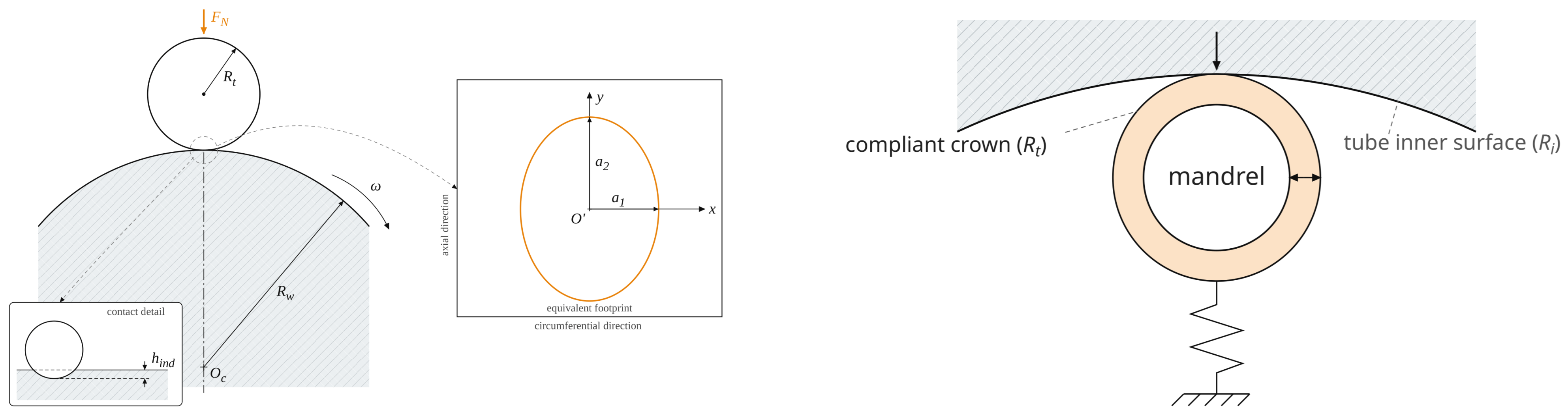
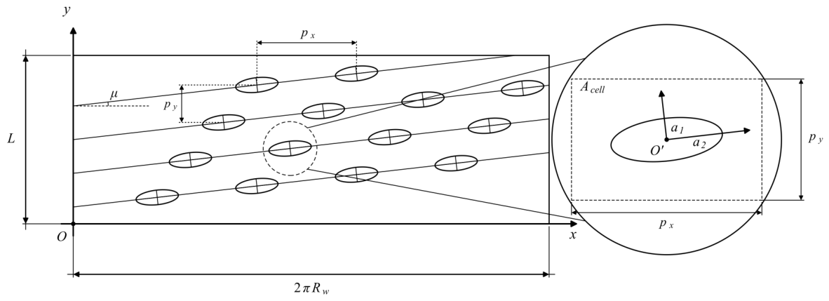
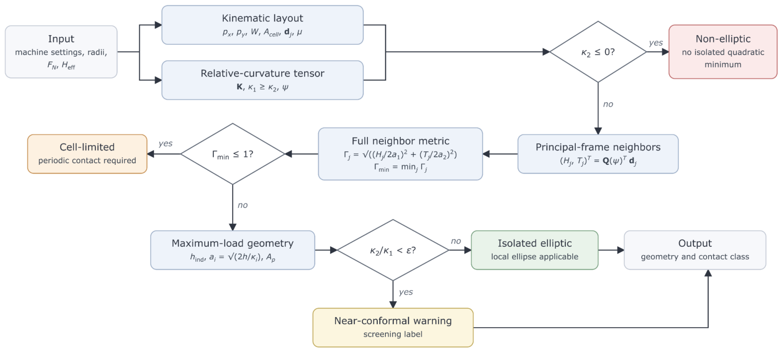
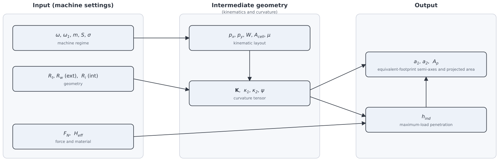
The external and internal cylinder configurations define the radii, force, indentation depth, equivalent footprint axes, cell dimensions, pitch, and orientation used in the model. Figure 1 and Figure 2 define the contact configurations and unwrapped-surface coordinates, respectively; Figure 3 and Figure 4 give the computational sequence and dependency structure, respectively.

2.2. Unwrapped Cell, Pitch, and Center Shift

The local cylindrical surface is unwrapped onto a plane with a circumferential coordinate x and axial coordinate y:
x = r θ , y = z ,
where r is the cylinder radius and θ is the angular coordinate. If k = | ω 1 / ω | is the speed ratio, and m is the number of balls, then the number of imprinting events per workpiece revolution is m k . The cell parameters are
p x = 2 π r m k , p y = S , W = S m k , A c e l l = p x p y ,
where p x is the circumferential pitch, p y is the row pitch after one workpiece revolution, W is the actual axial shift between two consecutive imprinting events, and S is the feed per revolution. For processing schemes in which the tool head produces no additional axial motion, W = S / ( m k ) . Carrier-induced axial motion modifies W through the corresponding kinematic relations. The distinction between W and p y is essential because the periodic unit cell governs overlap, density, and process-design calculations.

2.3. Orientation Angle and Two Kinematic Derivations

The imprint-axis angle μ is measured with respect to the circumferential axis. The velocity derivation starts from the circumferential and axial components of the velocity of the active contact point of the tool:
tan μ = v y v x .
For the perpendicular rotary-head scheme, carrier rotation contributes to the axial component. With a support radius R, ball radius ρ , and carrier-direction sign σ = ± 1 , the velocity components are given by
v x = 2 π r , v y = S + σ 2 π k ( R + ρ ) ,
which leads to
tan μ r o t = S + σ 2 π k ( R + ρ ) 2 π r .
For the parallel-axis vibro-rotary scheme, the carrier contribution changes the circumferential component of the active contact-point velocity. The corresponding expression is
tan μ v i b = S ( r + ρ ) 2 π r ( r + ρ ) + σ k ( R + ρ ) .
For the perpendicular rotary-head scheme, the relative active-point displacement is Δ x = 2 π r and Δ y = S + σ 2 π k ( R + ρ ) ; for the parallel-axis vibro-rotary scheme, it is Δ x = 2 π r [ ( r + ρ ) + σ k ( R + ρ ) ] / ( r + ρ ) and Δ y = S . In both cases, Δ y / Δ x = v y / v x . The displacement and velocity descriptions refer to the same active-point motion and yield the same imprint-axis orientation. This orientation is distinct from the slope of the line joining successive imprint centers, which is governed by the feed-to-pitch ratio (Section 2.4).

2.4. Internal-Tube Kinematics

The internal tube kinematics use the same unwrapped-surface construction with the tube’s inner radius R i and the crown event sequence. The reference layout is based on Russian Patent RU 2727127 C1 [39]. The tool consists of a cantilevered mandrel carrying a relief-forming roller whose outer ring is a compliant crown with N z alternating convex and concave elastic zones. As the mandrel rotates, the crown rolls over the inner surface of the tube, and each zone contacts the workpiece k times per mandrel revolution. The total number of imprinting events per tube revolution is therefore N z k . This kinematic layout is shared by a family of internal burnishing tools; the patented geometry in [39] serves as the reference configuration for the present calculations. The pitch values are
p x = 2 π R i N z k , p y = S ,
and the axial center shift between consecutive events is S / ( N z k ) . The slope α c of the line joining consecutive imprint centers is therefore
tan α c = S / ( N z k ) p x = S 2 π R i .
This center-line slope is distinct from the orientation μ of an individual imprint. The latter follows the relative motion of the active contact point:
tan μ = σ S 2 π R i k , σ { 1 , + 1 } .
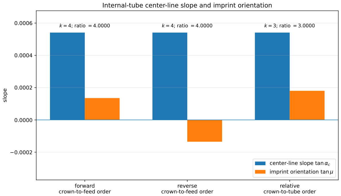
Indeed, v x = R i ω e v e n t , v y = S ω t / ( 2 π ) and ω e v e n t = k ω t give Equation (9). Equations (8) and (9) are thus linked by tan α c = k | tan μ | ; the event-order sign σ changes the imprint orientation but not the center-line slope.

2.5. Relative Curvature Contact Model

Let x = ( x , y ) T denote the coordinates in the tangent plane at the nominal contact point. For two smooth bodies in local contact, the normal gap is approximated by a quadratic form:
g ( x ) = g 0 + 1 2 x T K x + O ( x 3 ) ,
where K is the relative curvature tensor. We construct this tensor as the difference between the second fundamental forms of the tool and workpiece after both are expressed in the same tangent plane. This is the standard local construction used in classical contact mechanics [29,30]. If the principal-curvature tensor of the tool is K t , and that of the workpiece is K w , then
K = Q t T R t 1 1 0 0 R t 2 1 Q t s w Q w T R w 1 1 0 0 R w 2 1 Q w .
Here, R t i and R w i are signed radii of the curvature in millimeters, Q t and Q w are rotation matrices in the tangent plane, and s w defines whether the workpiece curvature is directed toward or away from the tool.
For a ball on an external cylinder, with the local x axis in the circumferential direction and the y axis in the axial direction, Equation (11) reduces to
K e x t = R t 1 + R w 1 0 0 R t 1 .
For a crowned roller inside a tube, the tube curvature subtracts from the active tool curvature, and the local tensor can be written before any in-plane rotation as follows:
K i n t = R t 1 1 R i 1 0 0 R t 2 1 .
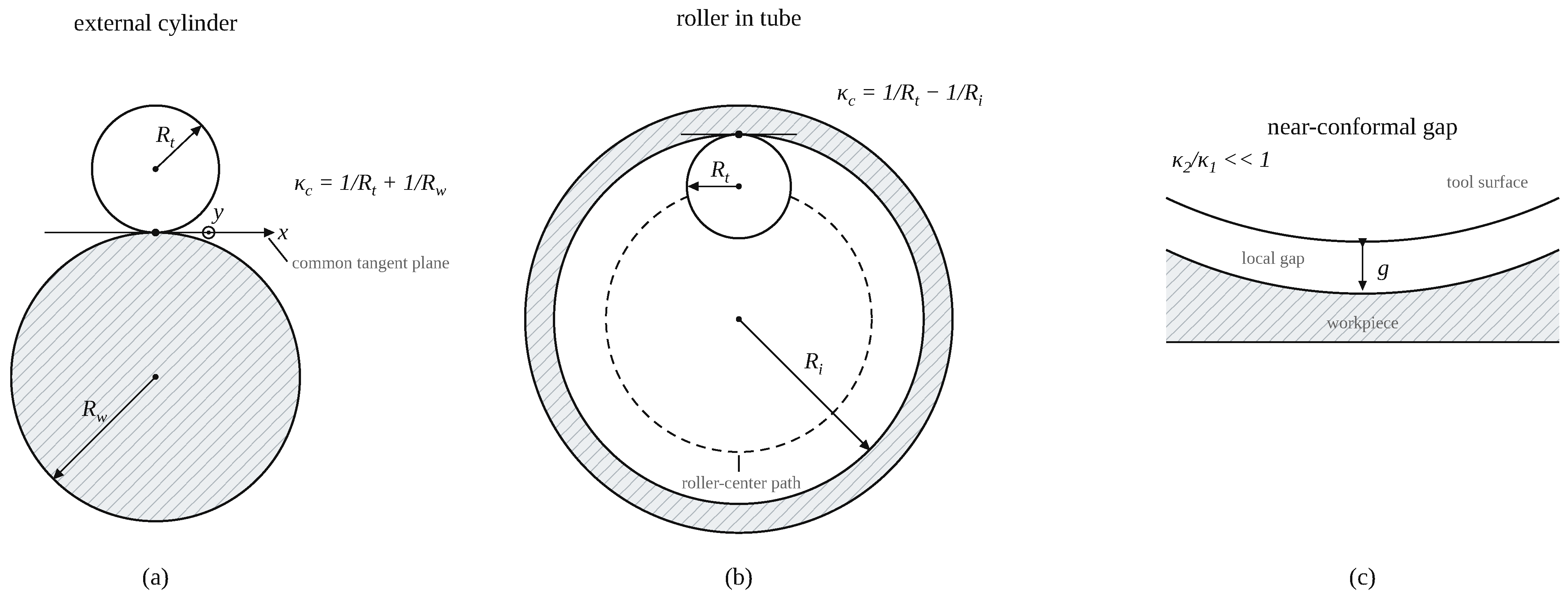
In Equation (12), the workpiece is convex, and thus s w = 1 in the convention of Equation (11). In Equation (13), the internal tube is concave, which corresponds to s w = + 1 . These two specializations show why the same tensor form covers both external and internal cylindrical geometries and why near-conformity appears when the first diagonal term in Equation (13) becomes small.

Non-Coincident Principal Axes

Equation (11) is not restricted to coincident tool and workpiece principal directions. If the two curvature frames are rotated relative to each other, then the resulting tensor generally contains an off-diagonal component, but the same eigenvalue analysis gives the principal curvatures and the orientation of the equivalent-footprint axes. For a symmetric tensor with components K 11 , K 22 , and K 12 , the angle ψ of the principal axis with respect to the chosen tangent basis satisfies
tan 2 ψ = 2 K 12 K 11 K 22 .
The branch is fixed by evaluating ψ = 1 2 atan2 ( 2 K 12 , K 11 K 22 ) or, equivalently, by using the normalized eigenvector associated with the larger eigenvalue. Thus, non-coincident axes require no new scalar case formulas; they are handled by the same tensor construction followed by eigenvalue extraction.
The eigenvalues of K are denoted by κ 1 κ 2 . Numerical values are reported in the units stated in each table and figure. The determinant and trace
I 1 = tr K = κ 1 + κ 2 , I 2 = det K = κ 1 κ 2 ,
are invariant under a rigid rotation of the tangent basis. If the basis is rotated by an orthogonal matrix Q , then K = Q T K Q . This similarity transformation preserves the eigenvalues, trace, and determinant. Figure 5 illustrates the tensor setting and the reference curvature cases.

2.6. Force-to-Depth Conversion

A rigid-plastic mean-pressure approximation defines the equivalent geometry at maximum load. The scalar H eff is a calibrated mean indentation pressure. Calibration may absorb the influence of flow stress, hardening, and rate dependence on the average pressure, but the scalar does not resolve elastic unloading, pile-up or sink-in, friction-induced changes in the contact boundary, or residual stresses. Consequently, the calculated depth and semi-axes describe the loaded state; residual dimensions require measured recovery or an unloading model.
For a positive definite local curvature state, the equivalent maximum-load footprint at penetration h is approximated by an ellipse. From the quadratic gap g = ( κ 1 x 1 2 + κ 2 x 2 2 ) / 2 , the boundary g = h gives
x 1 2 a 1 2 + x 2 2 a 2 2 = 1 , a i = 2 h κ i .
Thus, the projected area is
A p = π a 1 a 2 = 2 π h κ 1 κ 2 .
Unlike elastic Hertz contact, where the indentation depth scales as F N 2 / 3 , the rigid-plastic mean-pressure approximation assumes a nearly constant mean pressure, commonly related to the yield strength through p m H eff 3 σ y [29,40]. Hence, the normal force is proportional to the projected area F N = H eff A p . Substitution of Equation (17) gives
h ind = F N κ 1 κ 2 2 π H eff ,
With all quantities expressed in SI units, h ind is obtained in meters and reported in micrometers. At fixed F N and H eff values, Equation (17) and F N = H eff A p give A p = F N / H eff ; the curvature changes h ind and the semi-axis ratio, not the total projected area.

2.7. Applicability Classes

Let d j ( x y ) be the vector from an imprint center to neighbor j in the unwrapped circumferential–axial basis. Its components in the principal frame of the relative curvature tensor are
( H j , T j ) T = Q ( ψ ) T d j ( x y ) .
For the reference internal tube cases, ψ = 0 and | μ | 1.81 × 10 4 rad. Thus, the two directions are numerically nearly coincident at the scale of the reference cases; nevertheless, the neighbor transformation is defined by ψ and not by μ . Overlap with the reference ellipse is evaluated by the full normalized metric
Γ j = H j 2 a 1 2 + T j 2 a 2 2 , Γ min = min j Γ j .
A neighbor reaches the equivalent footprint when Γ j 1 . For identical, equally oriented equivalent footprints, Equation (20) gives the exact tangency boundary. For unequal or differently oriented footprints, Equation (20) serves only as a screening criterion. The exact relative center boundary is the Minkowski sum of one footprint and the reflection of the other. Because an ellipse is centrally symmetric, reflection produces the same ellipse, and the boundary reduces to the ordinary Minkowski sum of the two ellipses. The component ratios
η 1 = 2 a 1 p 1 , η 2 = 2 a 2 p 2
apply only to pitch vectors aligned with the principal axes: Γ ( p 1 , 0 ) = 1 / η 1 and Γ ( 0 , p 2 ) = 1 / η 2 . Both principal-frame components must be included; a small component by itself does not establish overlap when the other component is large.
The near-conformal quantity is the curvature ratio κ 2 / κ 1 . Because Equation (16) gives
a 2 a 1 = κ 1 κ 2 ,
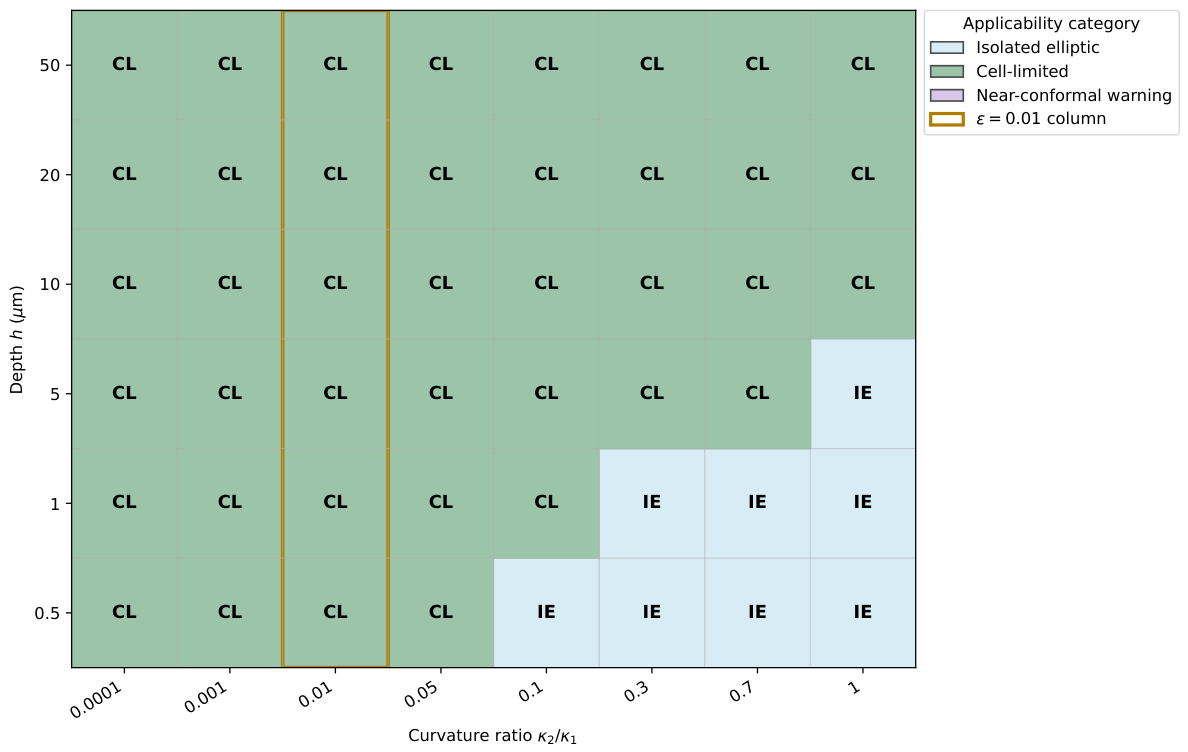
the screening threshold ε = 0.01 corresponds to a 10:1 footprint-to-aspect ratio. The qualitative loss of applicability of local contact formulas with increasing conformity has been documented for elastic Hertzian contacts, where finite-element solutions diverge from Hertz theory as the contact arc approaches the radii of curvature [41]. Accordingly, ε = 0.01 is used only as a 10:1 aspect ratio warning level; it is not a universal transition constant. The independent neighbor metric determines the cell-limited boundary.
The mutually exclusive classification is defined as follows:
C = non - elliptic , κ 2 0 , cell - limited , κ 2 > 0 and Γ min 1 , near - conformal warning , Γ min > 1 and κ 2 / κ 1 < ε , isolated elliptic , otherwise .
The kinematic layout and curvature tensor are independent of the normal force; the classification boundary, however, shifts with F N because the footprint semi-axes scale as h (Equation (16)). The term cell-limited denotes a physically admissible periodic-contact regime outside the isolated imprint model. A non-elliptic state instead indicates that the quadratic gap lacks an isolated minimum, and thus the ellipse formulas are not used.

3. Results

3.1. Analytical and Computational Verification

Table 1 presents the analytical identity and consistency checks for the kinematic and curvature relations.

3.2. External Cylinder Kinematics

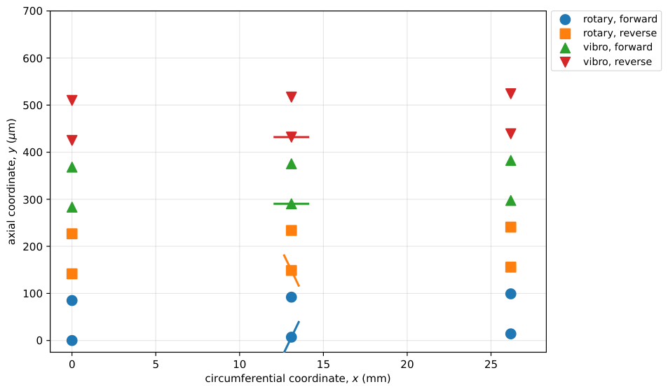
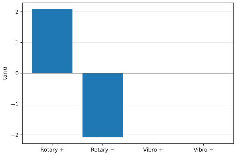
For r = 25 mm , m = 3 , k = 4 , and S = 0.085 mm / rev , Equation (2) gives p x 13.09 mm , p y = 85.0 μ m , W = 7.08 μ m , and A c e l l 1.11 × 10 6 μ m 2 . Table 2 lists the corresponding orientation angles for the two kinematic schemes. The perpendicular rotary scheme produced a large orientation angle, whereas the parallel vibro-rotary scheme stayed close to the circumferential direction.
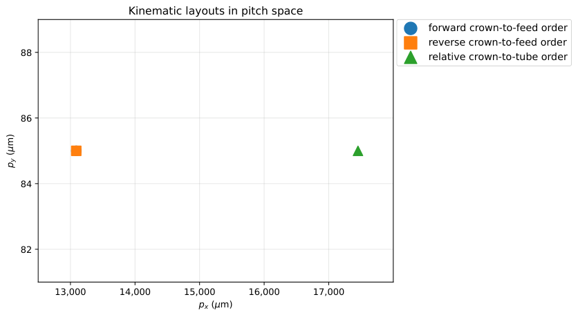
Carrier reversal changed the sign of the perpendicular scheme orientation, whereas the parallel scheme orientation was close to zero; the forward and reverse layouts coincided in pitch space (Figure 6, Figure 7 and Figure 8).

3.3. Internal Tube Kinematics and Sequence Verification

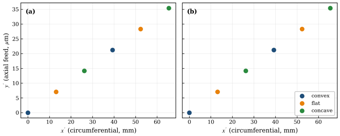
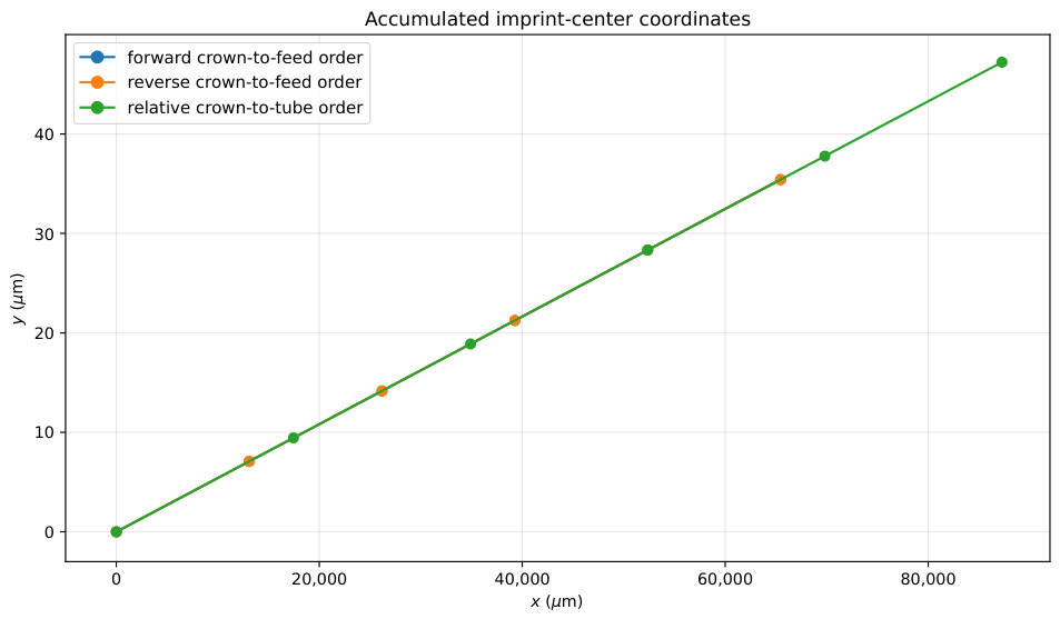
All three event orders produced nearly circumferential imprint axes and satisfied tan α c = k | tan μ | . The unwrapped coordinates increased axially with the event index and circumferentially with the event sequence (Table 3 and Figure 9, Figure 10 and Figure 11).
3.4. Curvature-Controlled Indentation and Contact Class

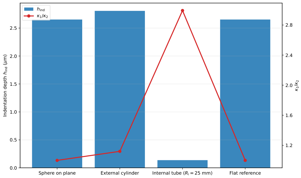
Table 4 gives the reference curvature cases under the same normal force and effective hardness. A sphere on a plane and the flat reference case gave identical tensor invariants. The external cylinder case increased the circumferential curvature and therefore increased the indentation depth calculated from the force. The internal tube case used R i = 25 mm for both the kinematic pitch calculation and the curvature calculation, with κ 1 = R t 1 1 R i 1 = 29.93 m 1 and κ 2 = R t 2 1 = 10.00 m 1 for the crown profile radius R t 2 = 100 mm. It had a lower maximum-load penetration and a more elongated equivalent footprint. The projected area was A p = F N / H eff = 50,000 μ m 2 in every row.
An illustrative example with non-coincident principal axes demonstrated the use of the full tensor form. For the external cylinder reference with the workpiece curvature frame rotated by 10 ° in the tangent plane, Equation (11) gave a non-zero off-diagonal term while preserving the principal curvatures of the aligned case. The resulting values were K 12 = 6.84 m 1 , κ 1 = 373.33 m 1 , and κ 2 = 333.33 m 1 , and the equivalent-footprint axis was rotated by 10 ° . The tensor formulation represents misaligned tool and workpiece principal directions without separate case-specific equations.
The reference cases show the maximum-load indentation depth and curvature ratio in Figure 12. The applicability map in Figure 13 classifies each cell with Equations (16), (20) and (23) for the fixed value κ 1 = 333.33 m 1 and an axis-aligned neighbor pitch of 400 μ m . The near-conformal condition was evaluated only when the cell-limited condition was not met. When the smaller eigenvalue approached zero, Equation (16) caused the corresponding semi-axis to increase without bound in the local quadratic model; the contact area had to then be limited by cell geometry or by a higher-fidelity contact calculation.
Neither reference case triggered a warning at ε = 0.005 , 0.01 , or 0.02 ; the internal tube classification was determined independently by the row-neighbor metric (Table 5).
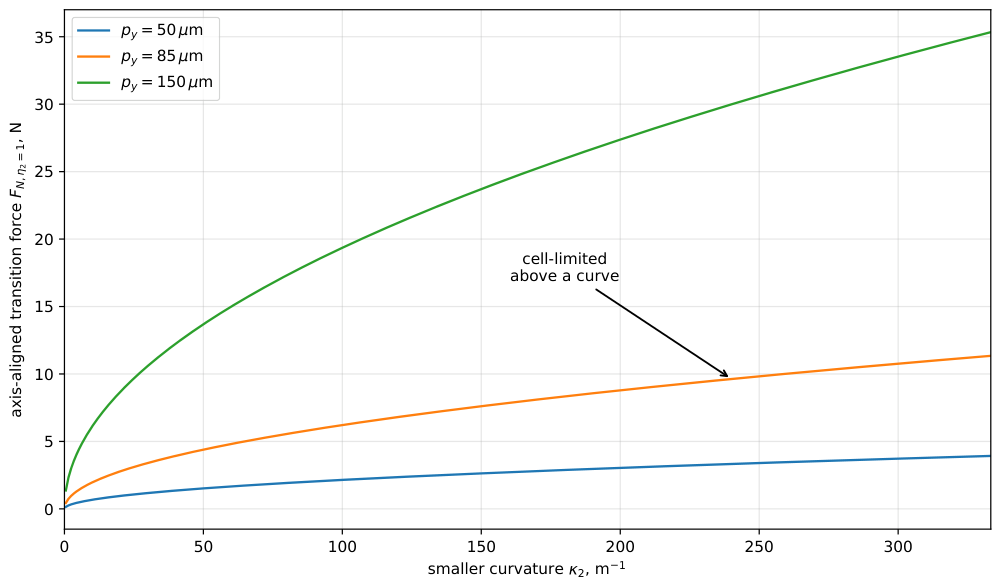
For an axis-aligned row-pitch neighbor, the axis-aligned cell-limited transition force followed from Γ j = 1 . The boundary associated with the second principal direction was obtained from η 2 = 2 a 2 / p y = 1 . Using Equation (16), this condition gave h = κ 2 p y 2 / 8 . Substitution into the force–depth relation (Equation (18)) yields
F N , η 2 = 1 = π H eff p y 2 4 κ 2 κ 1 .
Equation (24) is the axis-aligned special case of Γ j = 1 . For an inclined vector, the full expression in Equation (20) was used. Figure 14 plots the axis-aligned cell-limited transition force for representative row pitches. Above a given curve, the contact diameter in the second principal direction reaches the row pitch, and the cell-limited regime must be considered. Table 6 gives the same criterion for several internal tube diameters using p y = 85 μ m .
Beyond this boundary, the governing contact domain is periodic rather than an isolated equivalent footprint.
The values also quantify the error of a flat approximation. In the external-cylinder case, replacing the relative curvature tensor with the sphere-on-plane estimate gave h ind = 2.653 μ m instead of 2.807 μ m , a difference of about 5.8 % . For the unified internal tube case, κ 2 / κ 1 = 0.3341 gave a footprint aspect ratio of 1.7300 , outside the near-conformal warning band.

3.5. Neighbor Cell and Event Sequence Details

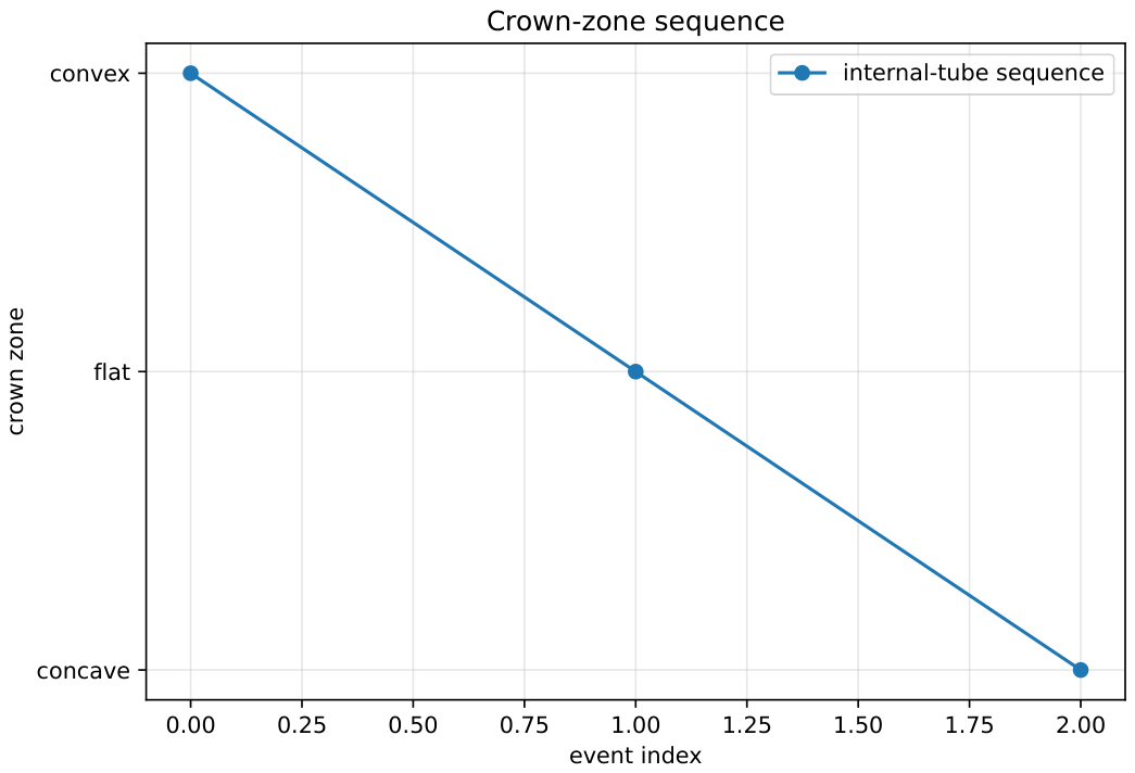
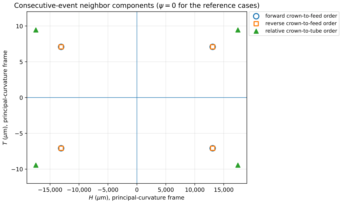
The transformed neighbor vectors confirm that consecutive events were separated, whereas the periodic-row neighbor controlled the classification (Table 7 and Figure 15). The crown-zone order that defined the event sequence on the unwrapped tube is shown in Figure 16.
At F N = 100 N, all consecutive-event metrics were much greater than unity, whereas the periodic-row metric was 0.256 . The reference case is therefore cell-limited because of the row pitch.

4. Discussion

4.1. Physical Interpretation and Comparison with Alternatives

Our formulation separates two physical effects that are often conflated in process descriptions. The kinematic part determines where imprints are located on the unwrapped cylindrical surface. The relative-curvature tensor determines how the tool and workpiece separate locally. This separation is useful because different machine settings may produce similar pitch values but different curvature states, and similar curvature states may be repeated at different spatial densities. The non-coincident axis example demonstrates the advantage of the tensor approach over separate scalar formulas: the same mathematical object automatically accounts for in-plane rotations without changing the model structure.
Compared with a finite-element simulation of each imprinting event, the tensor form is compact and analytically transparent. The local curvature and force–depth calculations require only the local radii, orientation matrices, normal force, and effective hardness. Compared with a purely empirical correlation, this preserves the sign of curvature and distinguishes non-elliptic, cell-limited, and near-conformal states within the same formulation. Recent reviews of finite-element ball-burnishing simulations indicate that numerical studies mainly focus on the residual stress, hardness, roughness, plastic strain, and surface integrity rather than on a curvature tensor formulation [15]. The proposed tensor construction therefore complements simulation-based models by providing a computationally inexpensive contact-conformity classification before a detailed forming simulation is performed.
Analytical wear and rolling-contact studies also show why this classification matters. The transition from non-conformal to conformal contact changes the pressure distribution and contact area evolution [37,38]. The contact state is classified as cell-limited when a neighbor reaches the footprint, independent of ε ; the threshold ε controls only the near-conformal warning.

4.2. Process-Planning Implications

For process planning, the kinematic relations can be used before a forming force is selected. The pitch and orientation determine the imprint density. The curvature tensor determines how large each equivalent maximum-load footprint becomes for a given force. Combining these quantities gives an initial estimate of the equivalent-footprint area fraction and overlap risk. For the stated hardness and row pitch, the 5–8 N axis-aligned limits were below the 100 N reference force used in Table 4. Published ball-burnishing forces on common engineering metals typically range from 50 to 500 N [42]; the axis-aligned transition force therefore lies one to two orders of magnitude below practical operating loads. The full metric must nevertheless be evaluated for each actual neighbor vector; a small coordinate component is not sufficient. If the pitch is too small relative to the footprint, then the force can be reduced, or the pitch can be increased; otherwise, the periodic contact must be modeled explicitly.

4.3. Post-Threshold Formulation

Once Γ min 1 , the isolated ellipse is no longer the governing contact domain. The appropriate post-threshold model is a periodic unit-cell unilateral contact formulation in which the full surface geometry and all active neighboring regions are solved simultaneously. Such a formulation must redistribute pressure between imprints, resolve plastic interaction and possible merging of loaded regions, and determine the real contact area from the union of active contact zones. The present work supplies the transition criterion and the cell geometry, but it does not solve the post-threshold pressure field.

4.4. Limitations

The verification in Section 3.1 establishes geometric identities and not process-specific accuracy. Process-specific imprint dimensions require calibration of H eff against direct measurements and comparison with the residual imprint after unloading.
The force–depth relation uses the rigid-plastic mean-pressure approximation. It omits elastic unloading, pile-up and sink-in, spatially varying strain hardening, strain rate dependence beyond calibration, frictional shear, thermal effects, and residual stresses. A scalar H eff may reproduce an average pressure after calibration, but it cannot resolve these mechanisms or the residual contact boundary.
The isolated-imprint equations apply only when K is positive definite and every relevant neighbor metric exceeds unity. The current model identifies the cell-limited transition; the post-threshold response requires the formulation described in Section 4.3.
The unwrapped cylinder preserves the circumferential arc length and axial distance, but the local gap uses a quadratic approximation and assumes contact dimensions that are small relative to the cylinder circumference. The forming element is geometrically rigid in the contact closure; compliant-crown deformation is represented only in the event layout and must be coupled separately when tool compliance is comparable with local contact compliance.

5. Conclusions

  • A unified kinematic map connects machine settings with the unwrapped imprint center lattice, row pitch, consecutive-event shift, and orientation for external cylinders and internal tubes, providing the geometric layout for process design calculations without requiring a force model. For the internal tube layout, the consecutive-center slope and imprint orientation are distinct quantities linked exactly by the event ratio k.
  • The relative curvature tensor provides a basis-invariant geometric formulation for aligned and misaligned principal directions. The tensor formulation recovers the external cylinder, internal tube, and limiting flat cases without separate scalar formulas and handles non-coincident principal axes through the same eigenvalue extraction.
  • Applicability is determined by an exclusive hierarchy combining tensor positivity with the full neighbor metric. The periodic-row neighbor places the reference case in the cell-limited class at the 100-N reference force, and no near-conformal warning is triggered for ε = 0.005 , 0.01 , or 0.02 .
  • The axis-aligned cell-limited transition force has a closed-form expression; for the stated internal tube row pitch and hardness, it was 5–8 N, well below typical burnishing loads. Neglecting workpiece curvature underestimated the predicted external cylinder indentation depth by 5.83 % relative to the full tensor calculation, independent of F N and H eff within the rigid-plastic mean-pressure approximation, while A p = F N / H eff . The absolute maximum-load dimensions require calibration, and residual dimensions require an unloading or recovery model.

Author Contributions

Conceptualization, methodology, formal analysis, and writing—original draft preparation, K.A.B.; supervision and writing—review and editing, A.V.Z.; formal verification and visualization, I.S.N. All authors have read and agreed to the published version of the manuscript.

Funding

This research received no external funding.

Data Availability Statement

The datasets and source code generated during the current study are available from the corresponding author upon reasonable request.

Conflicts of Interest

The authors declare no conflicts of interest.

Abbreviations

AbbreviationDefinition
FEMfinite element method
FFT-BEMfast Fourier transform boundary element method
SymbolDefinitionUnit
Roman symbols
A c e l l area of the unwrapped periodic cell mm 2 or μ m 2
A p projected contact area at maximum load mm 2 or μ m 2
a 1 , a 2 equivalent-footprint semi-axes along principal-curvature directionsmm or μ m
F N normal forming forceN
g , g 0 local gap and its constant termmm
H eff calibrated mean indentation pressurePa or GPa
H j , T j components of neighbor vector j in the principal-curvature framemm or μ m
h , h ind penetration; maximum-load indentation depthmm or μ m
I 1 , I 2 trace and determinant invariants of K mm 1 , mm 2
kspeed ratio | ω 1 / ω | in the external cylinder schemes and event ratio ω e v e n t / ω t in the internal tube scheme
Laxial length of the modeled unwrapped cylindrical surfacemm
mnumber of balls
N z number of crown zones
p x , p y circumferential pitch and row pitchmm or μ m
Rsupport radiusmm
R i tube inner radiusmm
R t active tool radiusmm
R w external workpiece radiusmm
ρ ball radiusmm
rcylinder radius in the unwrapped-surface kinematicsmm
Saxial feed per workpiece revolutionmm/rev
Waxial shift between consecutive imprint eventsmm or μ m
K , K t , K w relative, tool, and workpiece curvature tensors mm 1
Q , Q t , Q w in-plane orthogonal rotation matrices
v x , v y circumferential and axial velocity componentsmm/s
x , y circumferential and axial coordinates on the unwrapped surfacemm
Greek symbols
α c slope angle of the line joining consecutive imprint centersrad or deg
Γ j , Γ min full normalized neighbor metric and its minimum
η 1 , η 2 axis-aligned diameter-to-pitch ratios
ε screening threshold for the curvature ratio
κ 1 , κ 2 ordered eigenvalues of K mm 1 or m 1
μ imprint-axis orientation on the unwrapped surfacerad or deg
ψ principal-axis rotation in the tangent planerad or deg
σ carrier direction or event order sign
θ cylindrical angular coordinaterad
ω , ω 1
ω e v e n t , ω t
angular velocities defined in the corresponding kinematic schemerad/s

References

  1. Zhang, C.; Yu, W.; Yin, L.; Zeng, Q.; Chen, Z.; Shao, Y. Modeling of normal contact stiffness for surface with machining textures and analysis of its influencing factors. Int. J. Solids Struct. 2023, 262–263, 112042. [Google Scholar] [CrossRef]
  2. ISO 21920-2:2021; Geometrical Product Specifications (GPS)—Surface Texture: Profile—Part 2: Terms, Definitions and Surface Texture Parameters. International Organization for Standardization: Geneva, Switzerland, 2021.
  3. GOST 24773-81; Surfaces with Regular Microshape. Classification, Parameters and Characteristics. Standards Publishing House: Moscow, Russia, 1981.
  4. Shneyder, Y.G. Operational Properties of Parts with Regular Microrelief, 2nd ed.; Mashinostroenie: Leningrad, Russia, 1982. (In Russian) [Google Scholar]
  5. Shneyder, Y.G.; Ambaryan, R.K. Investigation of contact stiffness of surfaces with regular microrelief. Proc. Acad. Sci. Armen. SSR Ser. Tech. Sci. 1987, 40, 8–11. (In Russian) [Google Scholar]
  6. Dzyura, V.; Maruschak, P. Optimizing the formation of hydraulic cylinder surfaces, taking into account their microrelief topography analyzed during different operations. Machines 2021, 9, 116. [Google Scholar] [CrossRef]
  7. Dzyura, V.; Maruschak, P.; Tkachenko, I.; Kuchvara, I. Ensuring a stable relative area of burnishing of partially regular microrelief formed on end surfaces of rotary bodies. Stroj. Cas.—J. Mech. Eng. 2021, 71, 41–50. [Google Scholar] [CrossRef]
  8. Dzyura, V.; Maruschak, P.; Prentkovskis, O. Determining optimal parameters of regular microrelief formed on the end surfaces of rotary bodies. Algorithms 2021, 14, 46. [Google Scholar] [CrossRef]
  9. Dzyura, V.; Maruschak, P.; Slavov, S.; Dimitrov, D.; Semehen, V.; Markov, O. Evaluating some functional properties of surfaces with partially regular microreliefs formed by ball-burnishing. Machines 2023, 11, 633. [Google Scholar] [CrossRef]
  10. Zhou, Z.-Y.; Zheng, Q.-Y.; Ding, C.; Yan, J.-Y.; Piao, Z.-Y. A review of the development of surface burnishing process technique based on bibliometric analysis and visualization. Int. J. Adv. Manuf. Technol. 2021, 115, 1955–1999. [Google Scholar] [CrossRef]
  11. Liu, Z.; Dai, Q.; Deng, J.; Zhang, Y.; Ji, V. Analytical modeling and experimental verification of surface roughness in the ultrasonic-assisted ball burnishing of shaft targets. Int. J. Adv. Manuf. Technol. 2020, 107, 3593–3613. [Google Scholar] [CrossRef]
  12. Nagit, G.; Dodun, O.; Slatineanu, L.; Ripanu, M.; Mihalache, A.; Hrituc, A. Influence of some process input factors on the main dimensions of the grooves generated during the ball vibroburnishing. IOP Conf. Ser. Mater. Sci. Eng. 2020, 968, 012007. [Google Scholar] [CrossRef]
  13. Nagit, G.; Slatineanu, L.; Dodun, O.; Ripanu, M.I.; Mihalache, A.M. Surface layer microhardness and roughness after applying a vibroburnishing process. J. Mater. Res. Technol. 2019, 8, 4333–4346. [Google Scholar] [CrossRef]
  14. Gurey, V.; Maruschak, P.; Hurey, I.; Dzyura, V.; Hurey, T.; Wojtowicz, W. Dynamic analysis of the thermo-deformation treatment process of flat surfaces of machine parts. J. Manuf. Mater. Process. 2023, 7, 101. [Google Scholar] [CrossRef]
  15. Becerra-Becerra, E.; Aguilera Ojeda, C.O.; Saldana-Robles, A.; Reveles-Arredondo, J.F.; Barco-Burgos, J.; Vidal-Lesso, A. A review of numerical simulation of ball burnishing process. Finite Elem. Anal. Des. 2023, 218, 103926. [Google Scholar] [CrossRef]
  16. Kovacs, Z.; Konya, G.; Marko, B.; Poka, G. Experimental and theoretical investigation of the influence of tool paths and burnishing parameters on the quality of the burnished surface by magnetic assisted ball burnishing. Results Eng. 2025, 27, 105779. [Google Scholar] [CrossRef]
  17. Swirad, S. Changes in areal surface textures due to ball burnishing. Materials 2023, 16, 5904. [Google Scholar] [CrossRef] [PubMed]
  18. Hong, M.S.; Ehmann, K.F. Generation of engineered surfaces by the surface-shaping system. Int. J. Mach. Tools Manuf. 1995, 35, 1269–1290. [Google Scholar] [CrossRef]
  19. Greco, A.; Raphaelson, S.; Ehmann, K.; Wang, Q.J.; Lin, C. Surface texturing of tribological interfaces using the vibromechanical texturing method. J. Manuf. Sci. Eng. 2009, 131, 061005. [Google Scholar] [CrossRef]
  20. Kurniawan, R.; Kiswanto, G.; Ko, T.J. Surface roughness of two-frequency elliptical vibration texturing method for micro-dimple pattern process. Int. J. Mach. Tools Manuf. 2017, 116, 77–95. [Google Scholar] [CrossRef]
  21. Moriwaki, T.; Shamoto, E. Ultrasonic elliptical vibration cutting. CIRP Ann. 1995, 44, 31–34. [Google Scholar] [CrossRef]
  22. Su, Q.; Su, G.; Shen, X.; Wang, B.; Du, J.; Zhang, P. Design of an ultrasonic elliptical vibration cutting tool based on an eccentric cone. Int. J. Adv. Manuf. Technol. 2023, 124, 1003–1016. [Google Scholar] [CrossRef]
  23. Ling, Z.; Wang, D.; Wu, S.; Takao, A.; Wan, L. Development of ultrasonic elliptical vibration cutting and its application. Arch. Civ. Mech. Eng. 2025, 25, 140. [Google Scholar] [CrossRef]
  24. Mao, Y.; Zhang, Y.; Zheng, J.; Li, L.; Huang, Y.; Shi, S.; Wang, L.; Pei, J.; Li, Z. A study on micro-pit texture parameter optimization and its tribological properties. Machines 2024, 12, 475. [Google Scholar] [CrossRef]
  25. Bashmur, K.A.; Zagulyaev, A.V.; Nebylitsyn, M.V. A hybrid bionic strategy to enhance the static characteristics of roller-cone bit bearings using CFD simulations. SOCAR Proc. 2026, 27–36. [Google Scholar] [CrossRef]
  26. Bashmur, K.A.; Zagulyaev, A.V. Influence of surface texture on dynamic characteristics of rotor–bearing system of centrifugal pump. MIAB Min. Inf. Anal. Bull. 2026, 20–38. (In Russian) [Google Scholar] [CrossRef]
  27. Bhushan, B. Introduction to Tribology, 2nd ed.; Wiley: Hoboken, NJ, USA, 2013. [Google Scholar]
  28. Yu, X.; Sun, Y.; Zhao, D.; Wu, S. A revised contact stiffness model of rough curved surfaces based on the length scale. Tribol. Int. 2021, 164, 107206. [Google Scholar] [CrossRef]
  29. Johnson, K.L. Contact Mechanics; Cambridge University Press: Cambridge, UK, 1985. [Google Scholar]
  30. Kalker, J.J. Three-Dimensional Elastic Bodies in Rolling Contact; Kluwer Academic Publishers: Dordrecht, The Netherlands, 1990. [Google Scholar]
  31. Goryacheva, I.G.; Tsukanov, I.Y. Analysis of elastic normal contact of surfaces with regular microgeometry based on the localization principle. Front. Mech. Eng. 2020, 6, 45. [Google Scholar] [CrossRef]
  32. Tsukanov, I.Y.; Albagachiev, A.Y.; Danilov, V.D. Influence of the microprojection geometry on the elastic contact of surfaces with regular microrelief. Russ. Eng. Res. 2017, 37, 200–205. [Google Scholar] [CrossRef]
  33. Tsukanov, I.Y. Periodic contact problem for a surface with two-scale waviness. Mech. Solids 2018, 53, 129–136. [Google Scholar] [CrossRef]
  34. Tsukanov, I.Y. An extended asymptotic analysis for elastic contact of three-dimensional wavy surfaces. Tribol. Lett. 2019, 67, 107. [Google Scholar] [CrossRef]
  35. Mueser, M.H.; Dapp, W.B.; Bugnicourt, R.; Sainsot, P.; Lesaffre, N.; Lubrecht, T.A.; Persson, B.N.J.; Harris, K.; Bennett, A.; Schulze, K.; et al. Meeting the contact-mechanics challenge. Tribol. Lett. 2017, 65, 118. [Google Scholar] [CrossRef]
  36. Yastrebov, V.A.; Anciaux, G.; Molinari, J.-F. From infinitesimal to full contact between rough surfaces: Evolution of the contact area. Int. J. Solids Struct. 2015, 52, 83–102. [Google Scholar] [CrossRef]
  37. Santeramo, M.; Putignano, C.; Vorlaufer, G.; Krenn, S.; Carbone, G. Viscoelastic steady-state rolling contacts: A generalized boundary element formulation for conformal and non-conformal geometries. J. Mech. Phys. Solids 2023, 171, 105129. [Google Scholar] [CrossRef]
  38. Di Puccio, F.; Mattei, L. Simple analytical description of contact pressure and wear evolution in non-conformal contacts. Tribol. Int. 2023, 178, 108084. [Google Scholar] [CrossRef]
  39. Petrovskii, E.A.; Zenchenko, S.V.; Bashmur, K.A. Method for Rolling of Regular Relief on Inner Surface of Pipes and Device for Its Implementation. Russian Patent RU 2727127 C1, 20 July 2020. (In Russian) [Google Scholar]
  40. Tabor, D. The Hardness of Metals; Clarendon Press: Oxford, UK, 1951. [Google Scholar]
  41. Ciulli, E.; Betti, A.; Forte, P. The applicability of the Hertzian formulas to point contacts of spheres and spherical caps. Lubricants 2022, 10, 233. [Google Scholar] [CrossRef]
  42. Raza, A.; Kumar, S. A critical review of tool design in burnishing process. Tribol. Int. 2022, 174, 107717. [Google Scholar] [CrossRef]
Figure 1. Contact configurations considered in the model: external cylinder indentation and equivalent maximum-load footprint geometry, including the principal semi-axes (left) and internal tube contact with a compliant crown and concave workpiece curvature (right).
Mca 31 00155 g001
Figure 2. Unwrapped cylindrical surface with circumferential coordinate x = r θ and axial coordinate y = z . The periodic layout is defined by the circumferential pitch p x , row pitch p y , consecutive-event shift W, and imprint orientation μ ; a 1 and a 2 are measured in the principal curvature frame.
Mca 31 00155 g002
Figure 3. Computational sequence of the proposed model. Machine parameters define the kinematic layout and relative curvature tensor. The exclusive hierarchy is non-elliptic, cell-limited according to Γ min , near-conformal warning, and otherwise isolated elliptic.
Mca 31 00155 g003
Figure 4. Dependency matrix of the kinematic–curvature model. Machine settings and geometry determine the kinematic layout and relative curvature tensor; the force and calibrated mean-pressure parameter then determine the maximum-load penetration, equivalent footprint semi-axes, and projected contact area.
Mca 31 00155 g004
Figure 5. Tensor geometry for rotational burnishing. The local basis ( x , y ) is tangent to the cylindrical surface, R t denotes the tool radius in the active direction, R w is the external workpiece radius in panel (a), R i is the tube’s inner radius in panel (b), and κ 1 and κ 2 are the eigenvalues of the relative curvature tensor; panel (c) shows the local gap g near the common tangent plane in the near-conformal limit κ 2 / κ 1 1 .
Mca 31 00155 g005
Figure 6. Reference center layout on the unwrapped cylindrical surface. The circumferential coordinate is plotted in millimeters, and the axial coordinate is plotted in micrometers to show both the large circumferential pitch and the small row shift. Short line segments indicate the imprint-axis orientation. Rotary denotes the perpendicular rotary-head scheme; vibro denotes the parallel-axis vibro-rotary scheme.
Mca 31 00155 g006
Figure 7. Change in tan μ caused by carrier reversal. The perpendicular scheme changes the sign of a large axial-velocity contribution, whereas the parallel scheme is close to zero because the carrier contribution enters the circumferential denominator. Rotary+ and Rotary− denote the perpendicular rotary-head cases for σ = + 1 and 1 , respectively; Vibro+ and Vibro− denote the corresponding parallel-axis vibro-rotary cases.
Mca 31 00155 g007
Figure 8. Computed layouts in pitch space, with orientation encoded by color. The points for forward and reverse coincide completely.
Mca 31 00155 g008
Figure 9. Internal tube imprint layouts on the unwrapped cylindrical surface: (a) forward and reverse crown-to-feed sequences, giving 12 imprints per tube revolution with a circumferential step of 13.1 mm; (b) relative crown-to-tube sequence, giving 9 imprints per revolution with a step of 17.5 mm. In both panels, the imprint rows are nearly aligned with the circumferential direction ( μ 0.01 ° ). Zone labels indicate the convex, flat, and concave crown zones of the compliant crown; flat denotes the transition between convex and concave zones. x is the circumferential coordinate in the relative crown-to-tube frame.
Mca 31 00155 g009
Figure 10. Accumulated imprint center coordinates for the forward crown-to-feed, reverse crown-to-feed, and relative crown-to-tube event orders. The horizontal and vertical axes are the circumferential and axial coordinates on the unwrapped tube, respectively, and the marker order follows the event index.
Mca 31 00155 g010
Figure 11. Consecutive center slope tan α c and imprint orientation tan μ for the three internal tube event orders. Both quantities follow from the same kinematics and satisfy tan α c = k | tan μ | ; the sign of μ records the event order.
Mca 31 00155 g011
Figure 12. Indentation depth and curvature ratio for the reference cases at the same F N and H eff . Bars show h ind , the line shows κ 1 / κ 2 , and the projected area equals F N / H eff in all cases. The flat-reference row is an algebraic consistency check.
Mca 31 00155 g012
Figure 13. Applicability map for κ 1 = 333.33 m 1 and an axis-aligned neighbor pitch of 400 μ m . Each of the 48 cells was classified using Equations (16), (20) and (23); the highlighted κ 2 / κ 1 = ε column is a screening boundary and not an additional class.
Mca 31 00155 g013
Figure 14. Axis-aligned cell-limited transition force for η 2 = 1 . Above each curve, the second contact diameter reaches the corresponding row pitch at H eff = 2 GPa and a fixed value κ 1 = 333.33 m 1 .
Mca 31 00155 g014
Figure 15. Components H j and T j of the consecutive-event neighbor vectors in the principal frame of the relative curvature tensor. The plotted forward and reverse vectors coincide in this reference geometry; overlap classification used the full normalized metric Γ j .
Mca 31 00155 g015
Figure 16. Convex, flat, and concave crown zones over consecutive events. Flat denotes the transition between convex and concave zones. The plot represents kinematic event order; it does not represent pressure or deformation history.
Mca 31 00155 g016
Table 1. Verification hierarchy for the kinematic and relative-curvature results.
CheckVerification BasisResult
OrientationConsecutive-center slope and contact-point orientation from the same internal tube kinematics tan α c / | tan μ | = 4.0000 , 4.0000 , and  3.0000 , equal to the corresponding event ratio k
Tensor basis K = Q T K Q Eigenvalues, trace, and determinant preserved to numerical round-off
Limiting geometry R w ; R t 1 R i Sphere-on-plane limit recovered; the first internal relative curvature tends toward zero
Depth ratio h e x t / h f l a t = 1 + R t / R w 1.058 , i.e., a 5.83 % geometric increase independent of F N and H eff
Transition identitySubstitute Equation (24) into Equations (18) and (16) 2 a 2 / p y = 1 to numerical round-off
Table 2. Reference kinematic quantities for the external cylinder schemes.
Scheme and Carrier Direction tan μ μ (deg) p x ( μ m) p y ( μ m)
Rotary perpendicular, σ = + 1 + 2.081 + 64.33 13,090 85.0
Rotary perpendicular, σ = 1 2.079 64.32 13,090 85.0
Vibro-rotary parallel, σ = + 1 + 0.000189 + 0.0109 13,090 85.0
Vibro-rotary parallel, σ = 1 0.000631 0.0362 13,090 85.0
Table 3. Internal tube kinematic quantities and event-order cases.
Configuration p x ( μ m) p y ( μ m) A cell ( μ m 2 ) μ (deg)Event Order
Internal tube13,09085.0 1.11265 × 10 6 +0.00775forward crown-to-feed order
Internal tube13,09085.0 1.11265 × 10 6 −0.00775reverse crown-to-feed order
Internal tube17,45385.0 1.48353 × 10 6 +0.01034relative crown-to-tube order
Table 4. Reference curvature cases under the same load and effective hardness; h ind , a 1 , and a 2 describe the equivalent maximum-load state.
Case κ 1 ( m 1 ) κ 2 ( m 1 ) h ind ( μ m) A p ( μ m 2 )
Sphere on plane333.33333.332.65350,000
Sphere on external cylinder373.33333.332.80750,000
Crowned roller inside tube ( R i = 25 mm)29.9310.000.13850,000
Flat reference (algebraic check)333.33333.332.65350,000
Table 5. Sensitivity of the near-conformal screening threshold.
Case κ 2 / κ 1 a 2 / a 1 ε = 0.005 0.01 0.02
External cylinder0.89291.0583no warningno warningno warning
Internal tube ( R i = 25 mm)0.33411.7300no warningno warningno warning
Table 6. Illustrative axis-aligned cell-limited transition force for η 2 = 1 in internal tube layouts. The calculation used p y = 85 μ m , H eff = 2 GPa, κ 2 = 10 m 1 , and an active crown radius of 14.3 mm.
Tube Inner Diameter (mm) p x (mm) κ 1 ( m 1 ) F N , η 2 = 1 (N)
4010.4719.938.04
5013.0929.936.56
6015.7136.605.93
8020.9444.935.35
10026.1849.935.08
Table 7. Neighbor vectors in the principal-curvature frame for the unified R i = 25 mm internal tube geometry. C: ( + H , + T ) ; C 1 : ( H , + T ) ; C 2 : ( + H , T ) ; C - neg : ( H , T ) , where ( H , T ) are the principal-frame components defined in Equation (19).
CaseNeighborTypeH ( μ m)T ( μ m) Γ j Classification
forward crown-to-feed orderCconsecutive event13,0907.08368.238separated
forward crown-to-feed orderC1consecutive event−13,0907.08368.238separated
forward crown-to-feed orderC2consecutive event13,090−7.08368.238separated
forward crown-to-feed orderC-negconsecutive event−13,090−7.08368.238separated
forward crown-to-feed orderrow pitchperiodic row085.0000.256cell-limited
reverse crown-to-feed orderCconsecutive event13,0907.08368.238separated
reverse crown-to-feed orderC1consecutive event−13,0907.08368.238separated
reverse crown-to-feed orderC2consecutive event13,090−7.08368.238separated
reverse crown-to-feed orderC-negconsecutive event−13,090−7.08368.238separated
reverse crown-to-feed orderrow pitchperiodic row085.0000.256cell-limited
relative crown-to-tube orderCconsecutive event17,4539.44490.984separated
relative crown-to-tube orderC1consecutive event−17,4539.44490.984separated
relative crown-to-tube orderC2consecutive event17,453−9.44490.984separated
relative crown-to-tube orderC-negconsecutive event−17,453−9.44490.984separated
relative crown-to-tube orderrow pitchperiodic row085.0000.256cell-limited
Disclaimer/Publisher’s Note: The statements, opinions and data contained in all publications are solely those of the individual author(s) and contributor(s) and not of MDPI and/or the editor(s). MDPI and/or the editor(s) disclaim responsibility for any injury to people or property resulting from any ideas, methods, instructions or products referred to in the content.