Article

Multiphysics Design and Fuzzy-Based Optimization of Materials and Geometry for the Triple Scissor Deployable Antenna Mechanism

1
Department of Aeronautics and Astronautics, Institute of Space Technology, Islamabad 44000, Pakistan
2
Deanship of Scientific Research, King Abdulaziz University, Jeddah 21589, Saudi Arabia
3
Department of Applied Mathematics and Statistics, Institute of Space Technology, Islamabad 44000, Pakistan
4
Department of Mechanical Engineering, College of Engineering, University of Ha’il, Ha’il City 81451, Saudi Arabia
*
Author to whom correspondence should be addressed.
Math. Comput. Appl. 2026, 31(2), 52; https://doi.org/10.3390/mca31020052
Submission received: 3 March 2026 / Revised: 30 March 2026 / Accepted: 30 March 2026 / Published: 2 April 2026

Abstract

There is a demand for a structurally sound fire detection and suppression system that can support a large deployable ground or space antenna in a lower Earth orbit (LEO) environment and remains thermally stable across the entire range of the LEO environment. This paper describes a new type of deployable antenna, i.e., triple scissor deployable antenna mechanism (TSDAM), which has a circumferential modular structure and can deploy into position with one degree of freedom; its deployment does not change its geometric precision or structural stability. This research creates a comprehensive design methodology based on a multiphysics approach, which encompasses nonlinear kinematics analysis, fuzzy logic-based material selection, structural and thermal optimization using fuzzy logic geometries, coupled thermo-structural-dynamic analysis, and finally, dynamic analysis of the deployed structure. The material selection process identified the most suitable candidate material to be the T1100G carbon fiber reinforced plastic as its stiffness-to-weight ratio and thermal performance under LEO cycling was the best in the study. The optimal geometric deployment yield for the antenna was 26.8 m with a total structural weight of 128.4 kg and the base case geometric deployment yielded a feasible ratio of 0.91. This work provides a comparison of the mass savings using traditional deployable truss designs; testing of conventional designs showed a much greater mass overhead compared to the smart design’s mass. From a dynamic analysis perspective, the predicted fundamental frequency for the TSDAM as deployed was 0.09912 Hz and compared favorably to the corresponding finite element models (1.91% error), thereby validating the analytical model. The overall test provides a systematic, scalable methodology for designing ultra-lightweight, geometrically precise deployable reflector systems that satisfy the requirements of next-generation space operations.

1. Introduction

A lot of research has been conducted on various deployable space structures because of the importance of large aperture satellite antennas, solar arrays and reflector systems for creating a space-based communication system. Fells and Escrig produced earlier designs for a family of space structures which could be deployed into their final forms based upon moving the two-dimensional plates comprising the structure [1] together using geometric coupling. Though this design allowed for the different motions of the plates to be synchronised, because the design was an expandable structure it was limited to use in small satellites due to being too heavy and having insufficient stiffness when scaled to larger apertures.
The majority of subsequent research focused on the modelling and controlling dynamic behaviour of deployable truss systems. For example, Furuya and Higashiyama used Kane’s equations to evaluate the dynamics of a variable geometry truss (VGT) and demonstrated that internal control forces would play a significant role in the behaviour of a VGT in microgravity [2]. Arduini introduced a discrete Fourier transform-based approach for modular structural dynamics, enabling spectral condensation and reduced-order modeling for ring-type deployable structures [3]. Nagaraj and Nataraju investigated flexible systems with locking mechanisms using finite element modeling and Lagrangian dynamics, successfully predicting locking time, joint response, and strain energy with experimental validation [4].
The investigation examines the challenges of thermally induced distortion and structural fidelity. Florio and Joslof created an analytical method to study the thermal distortion of large parabolic antennas, which established that maximum thermal distortion occurred at considerable distances from the antenna hub [5]. Experimental tests of the cable-stiffened pantograph deployable systems have validated the increased stiffness of the cable-stiffened pantographs, while demonstrating that they possess single degree of freedom Deployment characteristics [6]. For a higher degree of freedom structures refer to [7,8].
Numerous studies report ongoing scientific advancement in Multibody system kinematics and dynamics. Park has established a recursive and closed form equation to describe the motion of open chain manipulators, using Lie Group Theory and Riemannian Geometry; in addition, these results may be applied to both closed-loop and flexible multibody systems [9]. Similarly, Legnani established a homogeneous transformation-based kinematic framework, enabling the analysis of velocity, acceleration, momentum and inertia to be performed using a unified methodology, thereby unifying classical mechanics with a modern kinematic view of motion based upon scientific principles [10]. Application of Newton-Euler techniques to parallel manipulators and over-constrained systems has demonstrably improved computer speed and accuracy for inverse dynamic problems alike [11,12].
Alternative modeling techniques were also proposed. Shi and Mophee combined linear graph theory with the principle of virtual work to develop symbolic dynamic equations for flexible multibody systems [13]. Arsenault and Gosselin conducted comprehensive kinematic, static, and dynamic analyses of tensegrity mechanisms, demonstrating the strong dependence of stiffness and workspace on geometry and internal forces [14,15]. The introduction to deployable tension-strut structures (DTSS) is based purely on geometric rules, which provide kinematic compatibility and structural stability using both passive cables and locking devices [16].
Multibody dynamics and applications of multibody dynamic analysis methods for deployable applications have gained significance in multidisciplinary design optimization of deployable structures. Recursive algorithms for multibody dynamic analysis of deployable structures were developed by Eberhard and Schiehlen; they noted that the dynamics of deployable structures involve nonlinear time-varying characteristics [17]. Jorgensen and Louis studied the deployment dynamics of elastically deployable solar arrays. Their results identified significant inconsistencies between predicted and measured/actual stiffness values due to degradation of the material used for manufacturing [18]. Shen and Montminy developed an extendable support structure (ESS) for telescopic antenna designs. They combined kinematic optimization and dynamic analysis to construct a system that would ensure that the support structure would be deployed in a synchronized fashion [19].
Two methods, Hamiltonian techniques and thermal-ductile coupling, were used to investigate the influence of slenderness and shear on deployable mechanism behavior [20]. Composite materials, including elastic memory polymers and self-deployable composite boom technology, were studied to investigate their thermal deployment characteristics [21]. Large amounts of research have been devoted to inflatable and textile-based deployable systems, and significant verification/control problems related to ground tests and dynamic modeling accuracy for these systems have been identified in the literature [22,23].
Numerous recent investigations into deployable antennas have concentrated on designing a large number of potential structural configurations in the form of one-ring or two-ring deployable truss mechanisms (linear frames), together with scissor mechanism (linear frames)-based systems, revealing significant advances over previous versions in terms of the project’s ability to maintain their orientation, stiffness and also the deployment of these structures [24,25,26,27]. Several manufacturing (prototype) techniques, demonstrated experimentally and numerically, show these mechanisms are viable for large mesh antennas. A new approach regarding the mechanical design of these types of mechanisms is by means of hexagon-based multi-segment designs (H-style and hexagonal segmented), improving overall structural symmetry, modularity of component parts and accuracy of deployment [28,29,30]. Using kinematic analysis methodology via screw theory, line geometry and closed-loop constraint methodologies, we have established that most deployable ring and prism structures offer only one method of control for their construction [31].

1.1. Literature Review

A significant body of past research has addressed truss- and ring-type deployments of deployable antenna structures. While early experiments demonstrated the feasibility of expanding large apertures, they had considerable limitations in both structural stiffness and scale. Typical fundamental frequencies for these types of systems have typically been in the range of 0.01–0.08 Hz [32]. Kanes’s formulation for dynamic modeling and multibody dynamics modelling have been common methods used to analyze the deployment of these antennas [33]. Substantial deployment stability has been produced with up to 10–15% deviations when testing the effects of internal actuation forces and constraints caused by the joints. The application of reduced-order models has allowed for increased computational efficiency; however, comparison of the accuracy of reduced-order models to full-scale finite element (FE) simulations often show approximately 5–10% differences due to materials and joint clearances [34]. Experimental testing has revealed differences in the area of 20 as a result of material imperfections, clearance around joints [35]. Current deployable antennas are deployed between 100–140 s [36]. However, deployable antennas systems are known to generally have both a high complexity associated with the actuation method and a very limited amount of overall Stiffness (or structural rigidity).
The proposed deployable antennas will provide significant benefits to space programs that will require deployable antennas with large apertures that have a low mass and have high reliability during deployment. These types of applications include earth observing satellites, SAR (synthetic aperture radar) satellites, deep space communication missions, and broadband communication satellites. The light-weight and thermally stable design will offer significant advantages for satellites that operate in both low earth orbit and geostationary orbit.

1.2. Research Gap

Deployable antennas currently available, including single-ring deployable antennas, double-ring deployable antennas and traditional-type scissor-style truss antennas, are all developed as realizable concepts for use in space; however, due to their ability to produce large aperture antennas in the future, deployable antennas produce long lead times for deployment, exhibit low stiffness due to size limitations and also weigh more than the classic types of give-and-take antennas. For example, previous studies on single-ring and double-ring deployable antennas of similar sizes have demonstrated that they require deployment times of 100–140 s and tend to resonate at very low frequencies (<0.09 Hz) and, as such, tend to have very low dynamic stiffnesses. In addition to long deployment times and low dynamic stiffnesses, the majority of existing work on deployable antennas is based on deterministic and deterministic design approaches, which often do not account for uncertainty caused by thermal loads, material property variations and manufacturing uncertainty. Therefore, it has been found that many of the best-performing designs developed for use in deployable antennas will perform poorly when deployed under the actual space environment. Additionally, there are a very limited number of calibrations performed to validate analytical models against multibody and finite element simulations, with respect to the coupled torque and vibration response that occur during the deployment of most antennas. Therefore, there is a significant gap in the knowledge and methodology of building deployable antenna systems that can be improved through the development of a scalable antenna architecture that will minimize the time needed for deployment, maximize the amount of stiffness that will be developed during deployment, minimize the overall mass of the antenna and address uncertainties in the build environment, supported by an analytical–numerical validation methodology. Most current deployable antenna systems can typically deploy within 100–140 s with a fundamental frequency of less than 0.09 Hz [34,36]. Both analytic and numeric forms of analysis report that some of these design discrepancies can be as large as 15–20 times because of varying material properties and differences in behavior of the joint [35]. The majority of currently used design methods are mainly based on deterministic optimization techniques therefore do not consider uncertainties presented by thermal cycling or variability in material properties [32]. This follows the reasoning behind developing methods to design with an understanding of uncertainty during the design process.

1.3. Motivation and Contributions

This research was motivated by the increasing need for large aperture deployable antennas to offer rapid, reliable deployment, high stiffness-to-weight ratio, and dimensional stability in extreme thermal environments. Furthermore, the limitations existing in current deployable antenna mechanisms (i.e., multi-degree-of-freedom complexity; deployment reliability issues resulting from synchronous connections; difficulty with analytical validation) led to the development of a new design that uses a single-degree-of-freedom (1DOF) deployable truss antenna utilizing a double-scissors linkage design.
This design will produce an antenna that has a large (deployed) to small volume ratio (stowed); greater strength and less actuation requirement due to geometry symmetry; and better deployment reliability. Currently deployed antennas larger than 20 m in size are typically equipped with conventional deployable mechanisms that take a long time to deploy and have excessive mass and low performance due to vibration effects on the antenna. A major limitation of most current designs is that they rely on deterministic optimization procedures, which do not capture the many uncertainties inherent in complex space missions. This leads to a need for a design methodology that will take account of these uncertainties in a robust manner.
The geometric models were created and simulated using Solidworks 2022 (2022, Dassault Systemes, Velizy-Villacoublay, France). Finite Element Analyses were performed in Ansys Workbench 2022 R2 (22.2, Ansys, Canonsburg, PA, USA), Analytical Calculations were completed with Matlab R2024a (24.1, MathWorks, Natick, MA, USA), and Multibody Dynamic Simulations were completed in MSC Adams 2021 (2021.2, MSC Software, Newport Beach, CA, USA). The computations for all simulations were conducted using a workstation equipped with an Intel Core i7 Processor (HP Intel, Santa Clara, CA, USA) (3.6 GHz), 16 GB RAM and running Windows 10.
The major contributions of this research are:
1.
Development of a new Triple Scissor Deployable Antenna Mechanism (TSDAM) that enables synchronized deployment using only one global degree of freedom during the deployment.
2.
Demonstration of rapid capability for the deployment process, including achieving full deployment in 53 s and completing an entire operational cycle in 102 s for a 25 m class antenna.
3.
Introduction of a fuzzy algebra based material selection framework for identifying the optimal material (T1100G CFRP) for maximum thermo-structural performance.
4.
Application of fuzzy geometry optimization for determining an optimized antenna diameter of 26.8 m.
5.
Analytical prediction of a fundamental natural frequency (0.09912 Hz) will be validated by finite element simulations with only 1.91% error.
6.
Comprehensive validation of analytical kinematic responses against SolidWorks and ADAMS simulations demonstrating excellent correlation for velocity and acceleration histories.

1.4. Novelty

This research presents an innovative approach that combines a triple-scissor deployable structure with a single multiphysics modeling system capable of simultaneously accounting for kinematic behavior, uncertainty of materials, temperature effects on material performance and optimization of overall structural design. In contrast to previous deployable antenna designs that utilize a multi-degree-of-freedom actuation and deterministic methods, this new design achieves synchronous deployment through the use of only one global degree-of-freedom, as well as a fuzzy optimization method that incorporates uncertainty into the optimization process. The integration of analytical modeling and validation through use of multibody and finite element modeling provides a comprehensive, highly scalable design process that has not been documented in any previous literature.

2. Geometric Configuration of the Deployable Antenna

Using an entire collection of identical modules arranged in a circular assembly about the perimeter of a reflector, is the deployable antenna system proposed in this document. The modules are made up of similar module types as described in this section, using triple scissor deployable units. The system is implemented via an integrated parametric and topological system rather than purely through local link-angle relationships as current geometric systems do. Therefore, the designer can use a scale factor for antennas with the same kinematic properties at both the project level (each individual scissor) and at the product level (the complete antenna).

2.1. Modular Topology

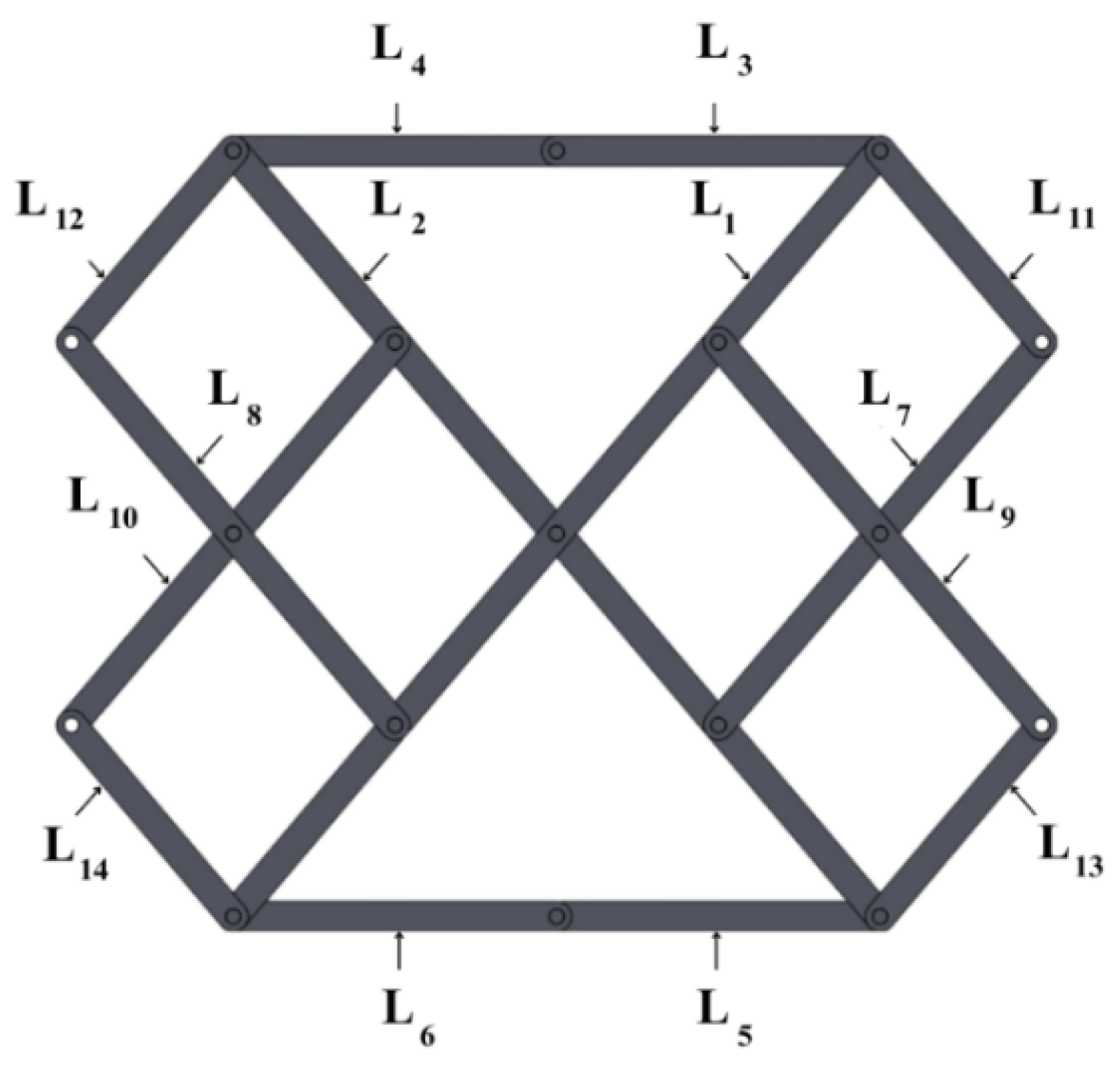
The modules are made from planar arrangements of scissor sub-units that have been interconnected, forming a triangulated truss system, as shown in Figure 1. The triangulated topology of the deployable truss contains rigid links that connect each scissor sub-unit to each other via ideal revolute joints, allowing for movement between the deployed position and the pack configuration. Let N n represent the number of nodes and links found within a single module.
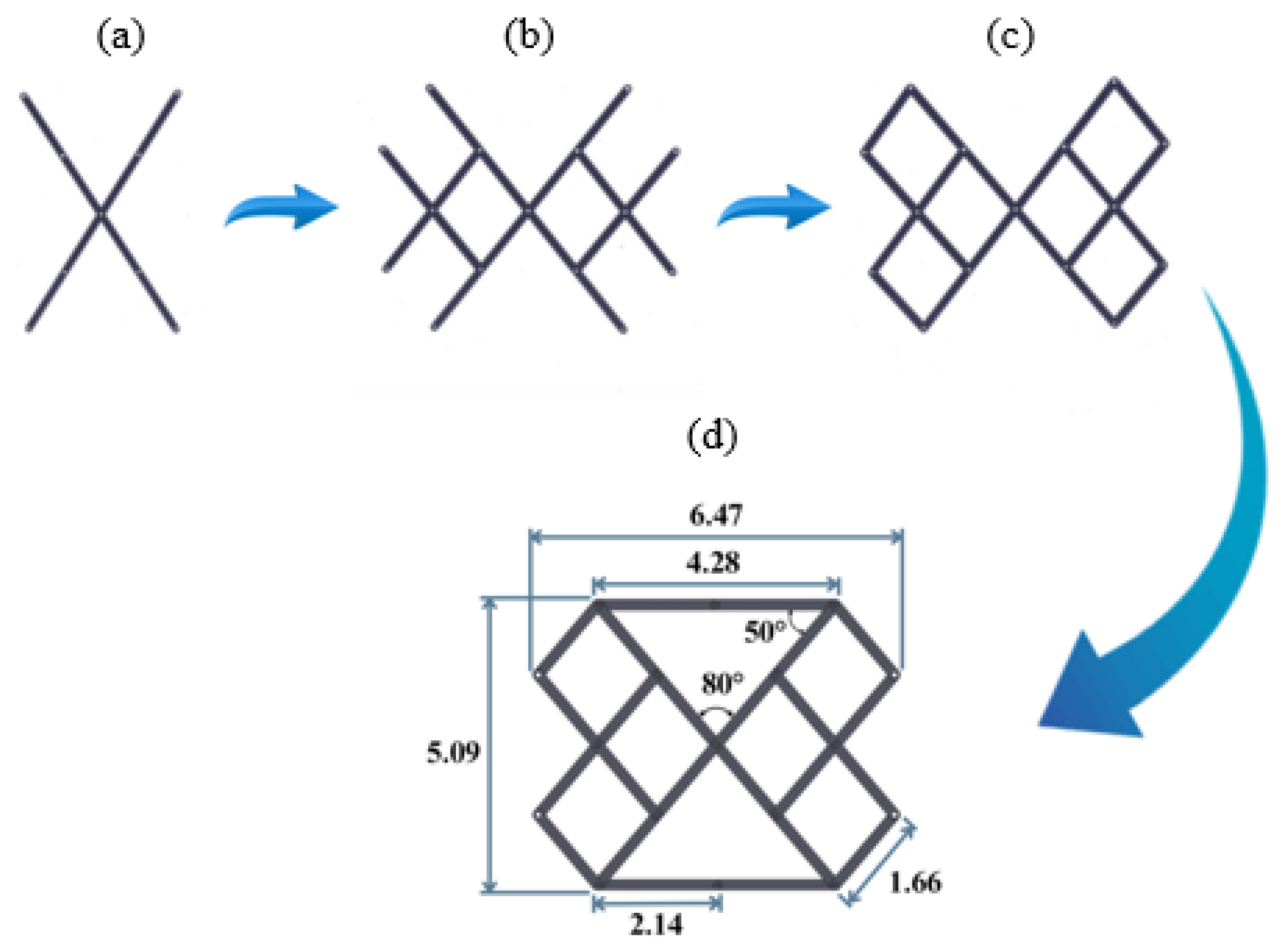
The complete antenna structure is obtained by uniformly distributing N m identical modules along a circular ring, as conceptually shown by the circumferential integration of the basic unit in Figure 2d. Adjacent modules share boundary nodes, which guarantees geometric continuity, force transmission, and deployment compatibility across the circumference.

2.2. Parametric Definition of Geometry

In a global polar coordinate system ( R , α ) , the deployed configuration of the antenna can be expressed as R refers to the deployed radius of the antenna and α is the circumference angular position of incremented angles between two adjacent modules. This is based on a formula that gives the angular spacing (in degrees) of adjacent modules
Δ α = 2 π N m .
Thus, the coordinates of the j-th node of the i-th module at its full extension are given by:
r i , j = R cos ( α i ) R sin ( α i ) z j , α i = i Δ α ,
where z j represents the height from the base of the j-th node relative to the module’s deployed position (as shown in Figure 1). The above parametric representation allows for compact representation of all antenna geometries regardless of number of units.

2.3. Stowed-to-Deployed Transformation

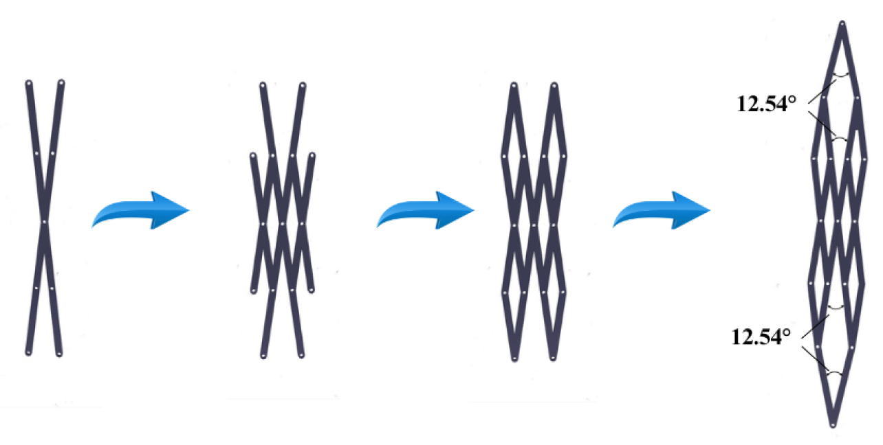
Antenna deployment is a continuous geometric transformation throughout the deployment process, where the geometric configuration is defined by a unilateral scalar parameter, λ , in the range of [ 0 , 1 ] . At the value of λ = 0 , the antenna is in the fully stowed position as per figure (Figure 3). At the value of λ = 1 , it is in the fully deployed position (Figure 1).
The point of the antenna as it deploys also has its coordinates defined by a linear interpolation between the stowed position and the deployed position.
r i , j ( λ ) = ( 1 λ ) r i , j stowed + λ r i , j deployed .
In addition, this allows for a seamless and kinematically compatible transition between overlapping forms through the deployment process while ensuring that all modules have connectivity to each other during deployment as well.

2.4. Geometric Scalability

One significant benefit of this geometric formulation is that it is inherently scalable within many of the same deployable module as depicted in Figure 2. Scaling the number of deployable modules ( N m ) as well as changing their radius ( R ) can generate antennas of different apertures with no change to any given module’s internal geometry. Therefore, this allows for one modular unit to be reused over multiple deployments to produce antennas that measure between 20–30 m in diameter while still maintaining the same deployment kinematics and structural topology. As a result of this scalability, this configuration is well suited for a variety of space mission needs.
The most critical assumptions made in the modeling are the idealization of joint connections and rigid link behavior. Real-world joint clearances and flexibility in materials create compliances that can reduce the overall structural stiffness while changing the dynamic response of the structure. Loosening those assumptions would likely result in lower natural frequencies and greater amounts of damping. Although the assumption of planar motion and quasi-static deployment simplifies the analysis, dynamic phenomena, including inertia and out-of-plane motion, may become significant during high-speed deployment scenarios.

2.5. Degree of Freedom Analysis

An evaluation of how deployable antennas work on a mobile robotic system will be made using a constraint-based method based on classical mechanism theory. The analysis will use a different approach than just standard generalized equations for mobility by taking into account the kinematic constraint(s) due to the closed loop(s) and joint(s) in a mechanism.

2.5.1. General Mobility Expression

For a planar mechanism, the theoretical mobility can be estimated using [37]:
M = 3 ( N 1 ) 2 J 1 J 2
where N is the number of rigid bodies, J 1 denotes the number of single-degree-of-freedom joints (revolute), and J 2 represents higher-pair joints. The theoretical mobility is determined using the Gruebler–Kutzbach criterion, which provides the number of degrees of freedom of a mechanism based on the number of links and joints. It represents the ideal kinematic mobility assuming no redundant constraints [37].

2.5.2. Constraint Redundancy in Closed Loops

Each deployable module contains multiple closed kinematic loops formed by scissor sub-units. These loops introduce geometric constraint redundancy, which reduces the effective mobility of the mechanism. Let C r denote the number of independent redundant constraints arising from loop closure conditions.
The corrected mobility is, therefore, expressed as:
M eff = M C r
The corrected mobility accounts for geometric constraints and redundant joints that are not captured in the theoretical mobility expression. This correction ensures an accurate representation of the actual degrees of freedom of the deployable structure.

2.5.3. Module-Level Mobility

At the module level, the scissors topology creates kinematic dependency of all the internal joints’ movement. The total number of redundant constraints is equal to the total number of independent loop equations within the module:
M module = 1
This implies that each module can be fully deployed or folded using a single actuation input. The mobility of each module is defined as M module = 1 because the scissor mechanism is designed to operate with a single independent input motion, ensuring synchronized deployment. This simplifies actuation and improves system reliability.

2.5.4. Assembly-Level Mobility

When N m modules are put together to make a circular antenna structure; because each adjacent module shares a joint at its boundary, these boundary joint(s) do not contribute to a new degree of freedom. Instead, these boundary joint(s) maintain compatibility among all the modules on the circumference of the antenna.
The total system mobility becomes:
M antenna = max M module , 1
Hence, the complete deployable antenna structure possesses a single global degree of freedom, enabling synchronized deployment of all modules.

3. Deployment Process Simulation in SolidWorks

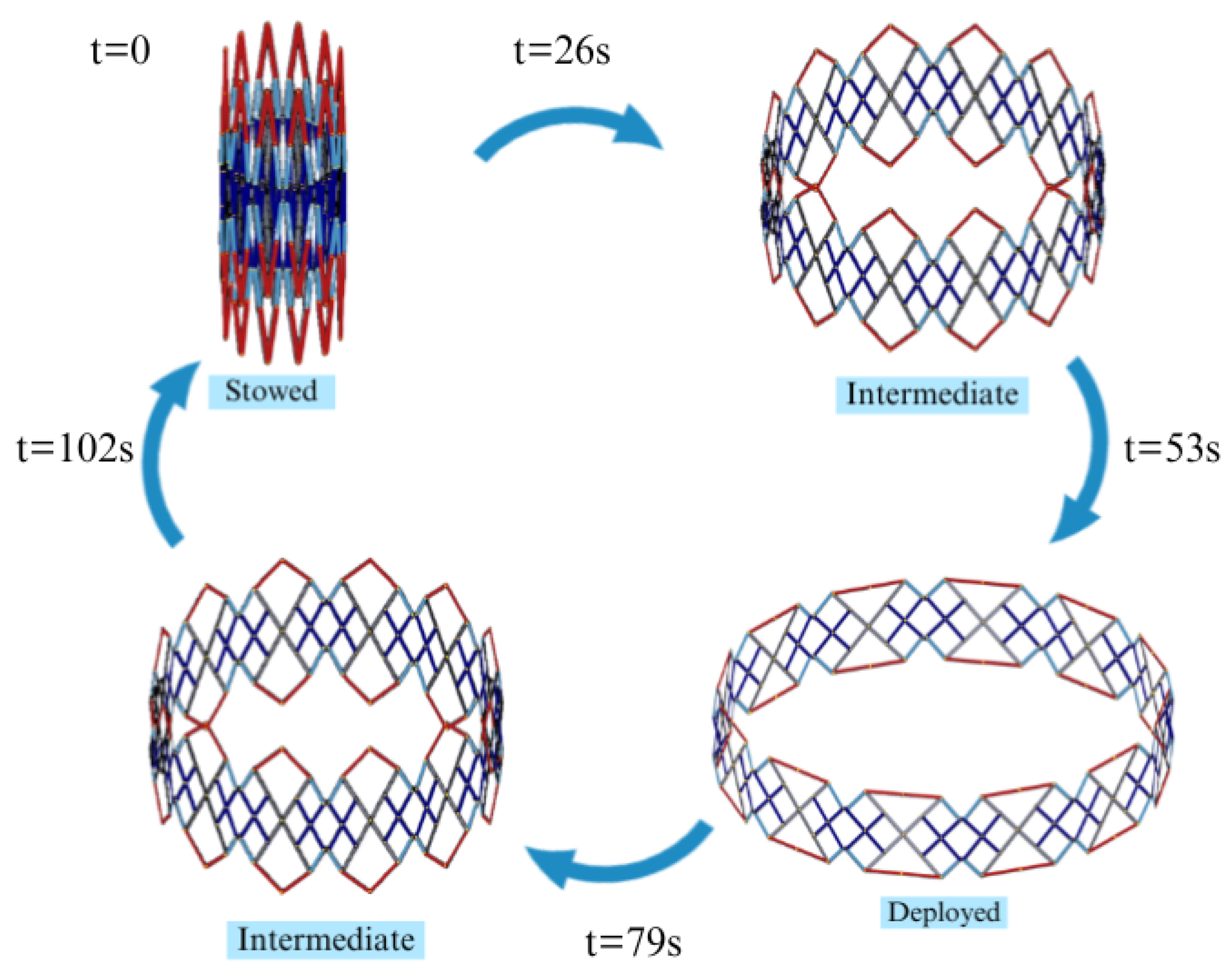
Through interconnected units in the 12-module deployable structure, Figure 4 shows the deployment progression from the stowed position to the fully deployed position, with each unit connected to the next unit in some manner. The stowed to fully deployed state of the deployable TSDAM is completed in 53 s, with a total cycle time of 102 s for the deployable TSDAM. A summary of the comparative analysis completed for the proposed 25 m TSDAM deployment is included in Table 1.
It can observed that the deployment process of proposed deployable mechanism is comparatively far more efficient than the single ring and double ring truss antenna that required 140 s and 102 s, respectively, to achieve fully deployed state.
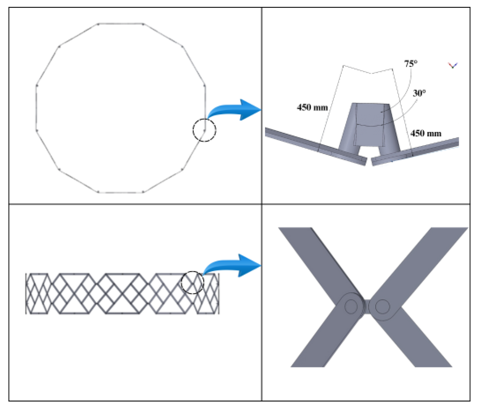
Figure 5 provides a zoomed-in view of the joint, highlighting its design and role in enabling smooth deployment and structural cohesion.

4. Material Selection Using Fuzzy Algebra and Decision Making

Space antennas designed to deploy are subject to strong limitations by the behavior of materials in thermal and mechanical environments with uncertainty. When deciding upon what material to use, the choice of material will largely affect how the entire structure will perform. Choosing materials which have a higher modulus of elasticity will improve natural frequency and lower deflection, while choosing materials with a lower specific gravity will reduce the overall mass of the system. The thermal properties of the material, especially the coefficient of thermal expansion (CTE), will directly impact dimensional stability. The use of carbon-fibre-reinforced polymers (CFRP) have resulted in higher stiffness; lower thermal distortion and higher overall system efficiency than their metallic counterparts. Traditional designing techniques rely on deterministic, or known, limits when selecting materials and utilize crisp optimization processes. Neither of these types of methods take into consideration the effects of epistemic uncertainty, variability within the manufacturing process, and/or uncertainty regarding the judgement of experts when selecting materials for deployable space antennas. In order to address these issues, the present study develops an alternative to the deterministic or crisp approach through a fuzzy algebra based multi-criteria decision making system using triangular fuzzy numbers and fuzzy normalization as well as fuzzy TOPSIS. For material selection, we are considering five different materials whose properties (Density (kg/m3), Young’s Modulus (YM) (GPa), CTE ( × 10 6 /K), Tensile Strength (TS) (MPa) and details are presented in Table 2.
This section describes a methodology utilizing a fuzzy logic-based framework for dealing with uncertainties relating to material selection for deployable antenna systems designed for harsh space environments. In Section 4.1 the triangular fuzzy representation of material properties is developed to consider the variability and impreciseness in material properties such as Young’s modulus, density and coefficient of thermal expansion; therefore, all material properties can now be represented as ranges instead of as fixed deterministic values. Developing fuzzy membership functions in Section 4.2 evaluates a material’s thermal survivability, or ability to actually survive the extreme thermally-induced stress produced by the extreme temperature variations found in Low Earth Orbit (LEO). The fuzzy membership function quantitatively measures how well each of the materials being evaluated meets the thermal performance requirements under uncertain conditions. Additionally, Section 4.3 demonstrates the application of the fuzzy Technique for Order Preference by Similarity to Ideal Solution (TOPSIS) method to rank candidate materials based upon multiple criteria, which, provides a systematic and quantitative comparison of identifying the candidate material which is closest to ideal solution and farthest from the worst-case solution. The methodology described herein provides for a robust and uncertainty-aware method for materials selection, which is critical for producing reliable deployable space structures.

4.1. Triangular Fuzzy Representation of Material Properties

Each material attribute is modeled using a triangular fuzzy number (TFN) defined as:
A ˜ i = ( l i , m i , u i )
where l i , m i , and u i denote the pessimistic (lower), most probable (modal), and optimistic (upper) values, respectively. These parameters capture uncertainties arising from experimental scatter, fabrication tolerances, and environmental variation.
  • The centroid-based defuzzification method is adopted:
A i = l i + m i + u i 3
The centroid-based defuzzification method computes a crisp value by determining the center of gravity of the fuzzy set. This method is widely used due to its stability and accuracy in representing fuzzy outputs [32]. The fuzzy arithmetic operations used in this study follow the classical fuzzy algebra rules:
A ˜ + B ˜ = ( l A + l B , m A + m B , u A + u B )
λ A ˜ = ( λ l A , λ m A , λ u A ) , λ > 0
Fuzzy membership functions are used to map input variables to a degree of membership between 0 and 1. Triangular membership functions are adopted due to their simplicity and computational efficiency [32,38].

4.2. Fuzzy Membership Modeling for Thermal Survivability

Thermal capability is assessed using fuzzy membership functions that replace traditional crisp limits.
The membership degree for high-temperature survivability is defined as:
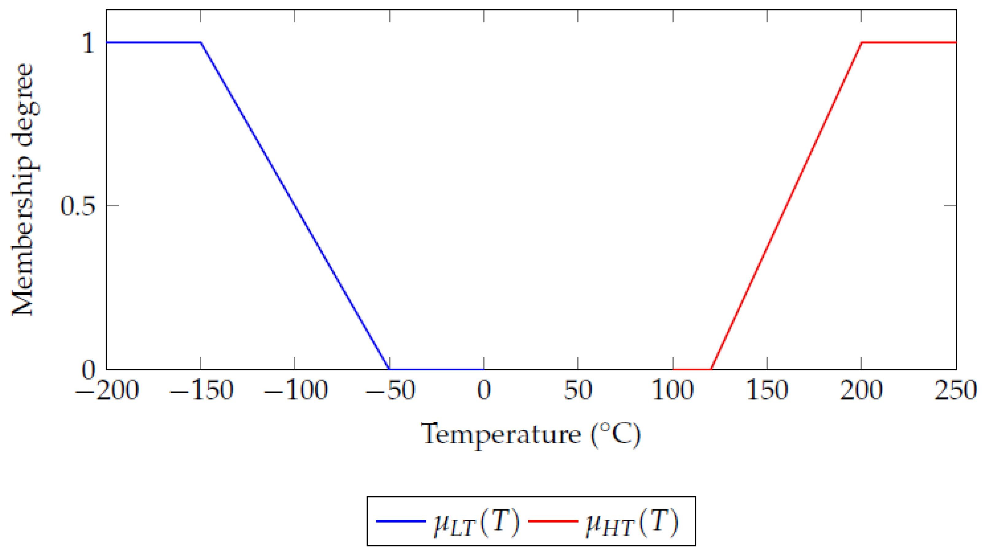
μ H T ( T ) = 0 T < 120   ° C T 120 80 120   ° C T 200   ° C 1 T > 200   ° C
The membership degree for low-temperature survivability is given by:
μ L T ( T ) = 1 T < 150   ° C 50 T 100 150   ° C T 50   ° C 0 T > 50   ° C
The membership degrees for high- and low-temperature survivability are defined based on material performance limits under thermal loading. Materials with lower thermal expansion and higher thermal resistance exhibit higher membership values, ensuring reliable operation in extreme environments.
  • The combined fuzzy thermal index is then evaluated as:
μ t h e r m a l , i = min μ H T ( T m a x , i ) , μ L T ( T m i n , i )
The combined fuzzy thermal index integrates multiple thermal performance indicators into a single scalar value. It reflects the overall thermal suitability of a material under uncertain environmental conditions, enabling direct comparison between candidate materials.

4.3. Fuzzy TOPSIS-Based Multi-Criteria Ranking

The fuzzy decision matrix is constructed as:
X ˜ = x ˜ 11 x ˜ 12 x ˜ 1 n x ˜ 21 x ˜ 22 x ˜ 2 n x ˜ m 1 x ˜ m 2 x ˜ m n
where m denotes the number of materials and n represents the selection attributes.
Fuzzy normalization is performed according to benefit and cost criteria:
r ˜ i j = x ˜ i j x j m a x , benefit attributes x j m i n x ˜ i j , cos t attributes
Fuzzy weights are assigned as:
W ˜ = { ( 0.35 , 0.40 , 0.45 ) , ( 0.30 , 0.35 , 0.40 ) , ( 0.10 , 0.15 , 0.20 ) , ( 0.05 , 0.10 , 0.15 ) }
corresponding to tensile strength, modulus of elasticity, density, and manufacturability, respectively. The fuzzy weights are assigned based on the relative importance of each criterion in deployable space structures. Structural stiffness and thermal stability are given higher weights due to their critical impact on performance. These weights are normalized and used in the aggregation process to ensure balanced decision-making.
The vertex-distance measure between two TFNs is defined as:
d ( A ˜ , B ˜ ) = ( l A l B ) 2 + ( m A m B ) 2 + ( u A u B ) 2 3
The fuzzy positive and negative ideal solutions are defined as:
A + = { max i u i j }
A = { min i l i j }
The closeness coefficient is computed as:
C C i = D i D i + + D i
The closeness coefficient measures the relative distance of each alternative from the ideal and negative-ideal solutions in the fuzzy TOPSIS framework. The aggregated fuzzy decision score represents the overall performance of each material by combining weighted criteria and ranking them accordingly. Finally, the aggregated fuzzy decision score is:
S i = α C C i + ( 1 α ) μ t h e r m a l , i , α = 0.7
The fuzzy ranking procedure clearly demonstrates in Table 3 that T1100G carbon-fiber reinforced polymer (CFRP) composites dominate metallic alloys due to their superior fuzzy strength-to-weight ratios and thermal resilience. Also, CFRP materials were chosen as they possess a significantly higher stiffness-to-weight ratio than comparable traditional metals, such as Aluminum and Steel. Additionally, CFRP possesses an almost zéro coefficient of thermal expansion, resulting in minimal deformation due to temperature changes when used in space. Both of those properties are critical for maintaining the structural integrity and stability of deployable antennae. This also shows that fuzzy based material selection method performs well.

5. Fuzzy Geometry Optimization of Deployable Structure

The geometric design of the deployable antenna is formulated as a fuzzy, multi-objective optimization problem. Unlike classical rigid constraints, fuzzy feasibility enables smooth trade-offs among competing design objectives.

5.1. Fuzzy Formulation of Objective Function

The fuzzy multi-objective performance index is defined as:
J ( x ) = w 1 f ˜ n ( x ) + w 2 m ˜ ( x ) + w 3 δ ˜ ( x )
where x = [ r , L 1 , , L 14 ] is the design vector, f ˜ n is the fuzzy natural frequency, m ˜ is fuzzy mass, and δ ˜ is fuzzy maximum deflection. The fuzzy formulation of the objective function is implemented to identify optimal design parameters under uncertainty. This approach enables simultaneous optimization of conflicting objectives such as minimizing mass while maximizing stiffness and minimizing deflection.

5.2. Membership-Based Soft Constraints

The fuzzy membership for frequency feasibility is defined as:
μ f r e q ( f ) = 1 , f f d f L f f L f d , f d < f < f L 0 , f f L
Similarly, fuzzy memberships are developed for radius ( μ r ) and deflection ( μ δ ). The overall feasibility degree is evaluated by the Bellman–Zadeh decision principle:
μ F e a s ( x ) = min ( μ f r e q , μ r , μ δ )

5.3. Hybrid Fuzzy Genetic Algorithm–SQP Framework

The global search is performed using a fuzzy genetic algorithm (FGA), followed by a local refinement using sequential quadratic programming (SQP). The FGA fitness function is:
F ( x ) = λ J ( x ) + ( 1 λ ) 1 μ F e a s ( x )
where J denotes the centroid-defuzzified objective function. The optimization problem is solved using a hybrid approach combining Genetic Algorithms (GA) and Sequential Quadratic Programming (SQP). GA provides global search capability, while SQP ensures fast local convergence [39]. Figure 6 shows the fuzzy membership functions for thermal survivability.

5.4. Results of Geometry Optimization

After using the above steps we got the optimized antenna configuration with a diameter of 26.8 m and a total mass of 128.4 kg was obtained, achieving a feasibility index of 0.91. So, the radius is 13.4 , and optimized lengths which are presented in Table 4. All lengths were derived from linear geometric scale calculations based on the base configuration design at 25 m and the angles, kinematic topology of all three modular scissor units have been maintained as deployed in this configuration.
Utilising fuzzy algebra to perform materials selection and optimisation of where geometrically positioned within the configuration, a substantial improvement has been achieved in the robustness of the design process. Fuzzy TOPSIS produced an unambiguous ranking hierarchy from the analysis—CFRP composites are consistently superior to metal alloy in terms of thermal surviving ability and mechanical efficiency both thermally surviving and mechanically effective.

6. Thermo-Structural Analysis of the Optimized Antenna

In order to assess the structural integrity and dimensional stability of the optimised deployable antenna in real world space environment, a coupled thermal-structural analysis was conducted. The coupled analysis included a steady state thermally stable condition prior to conducting a thermally quantitated static structural analysis using applied thermal loads applied as body loads.

6.1. Thermal Loading and Temperature Field

In preparing the model’s thermal loadings for this worst-case operational environment in space, a combination of solar radiation and radiative heat transfer to and from the surrounding space environment was accounted for. With steady-state thermal conditions on the antenna structure as the basis for this analysis, a steady state thermal analysis was carried out using prescribed temperature boundary conditions as prescribed by the thermal loads above to create the temperature distribution throughout the mounting.
The distribution of temperature was predicted through the heat conductive equations:
· ( k T ) + Q = 0 ,
where k is the thermal conductivity of the optimized material and Q represents external heat sources. The resulting temperature field serves as input for the subsequent static structural analysis. The external heating source represents the incoming thermal loads that come from the outer space environment, which include direct solar radiation, Earth Albedo, and IR radiation. The definition of the Heat Flux ( q ( t ) ) is that a positive value indicates that heat is coming into the structure, and a negative value indicates that heat is being dissipated from the structure to deep space through radiation. This convention has been used in Equation (23) to keep the thermal energy in balance.

6.2. Static Structural Analysis Under Thermal Conditions

The mechanical response of the antenna is evaluated through a static structural analysis incorporating the computed temperature field. Thermal strains are introduced into the structural model as equivalent nodal loads. The equilibrium equation is expressed as:
K u = F mech + F th ,
where K is the global stiffness matrix, u is the nodal displacement vector, F mech denotes mechanical boundary conditions, and F th represents thermally induced forces.

6.3. Thermo-Structural Response

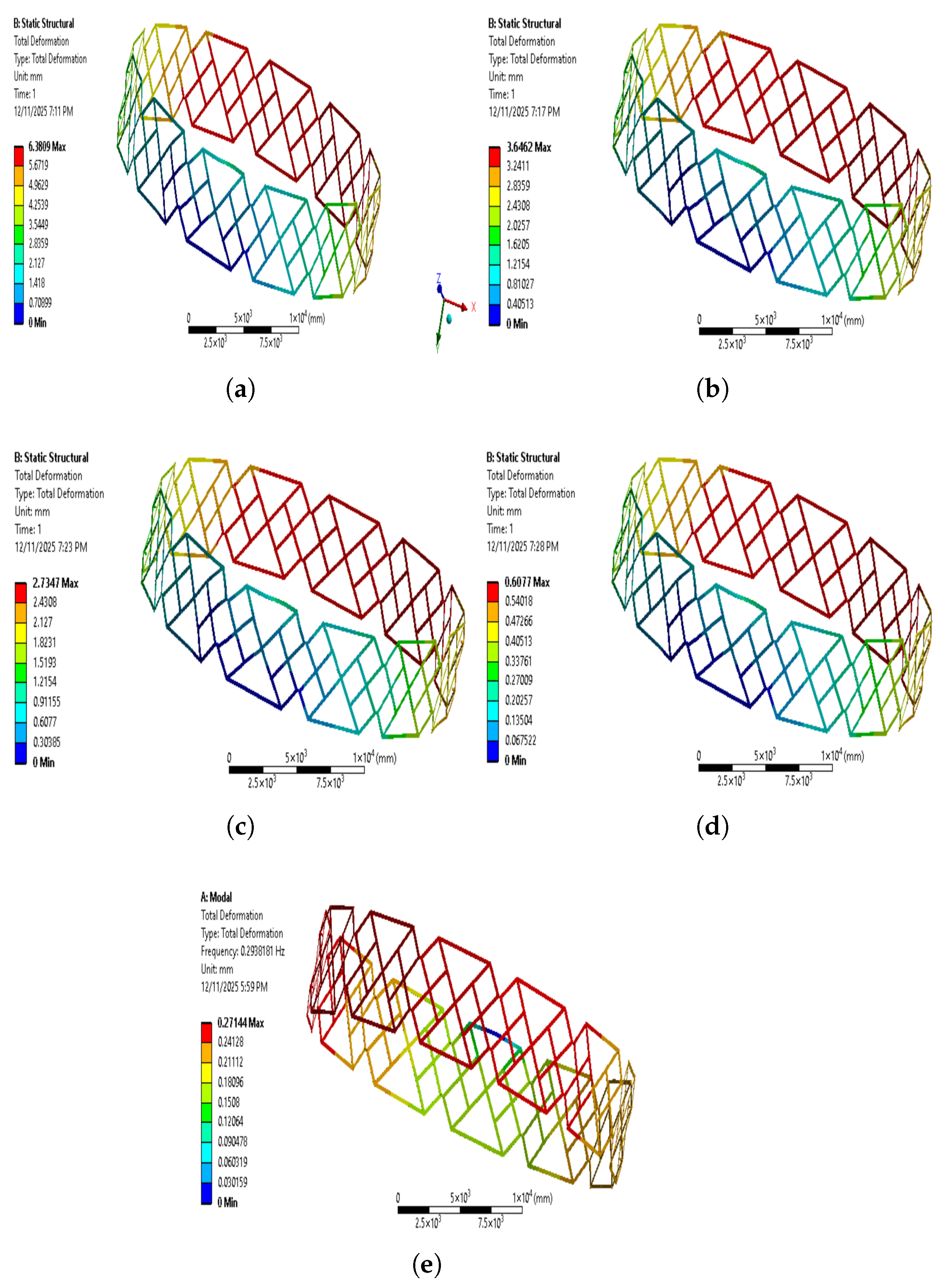
The thermo-structural response of the optimized antenna is evaluated in terms of strain, and deformation resulting from the static structural analysis under thermal conditions. A depiction detailing the total deformations on a thermal load due to each of five different candidate materials (Figure 7a) 4340 Steel, (Figure 7b) Al-7075 (Figure 7c) Ti-6Al-4V (Figure 7d) M55J CFRP, and (Figure 7e) T1100G CFRP for the thermal loading of the optimised Deployable Antenna from the static Structural Analysis can be seen in Figure 7. All five materials were compared in the same geometrical configuration, boundary conditions, and thermal loads so that the thermomechanical behavior of the materials could be evaluated separately.
In the case of metallic materials (4340 Steel versus Al-7075 versus Ti-6Al-4V), it can be seen that these materials show much greater deformation than their CFRP counterparts. Among the three metallic materials compared, Al-7075 produced the most deformed material, most likely due to its significantly lower elastic modulus and much higher coefficient of thermal expansion than the other two metallic materials. Even though 4340 Steel has a high stiffness, it also has a much greater density than the other two metals and a higher coefficient of thermal expansion, which, along with its high density, results in thermal expansion causing thermal deformation to occur. Although Ti-6Al-4V produced approximately 25% less thermal deformation than Al-7075 due to its higher stiffness-to-weight ratio, it still produced significant levels of thermal deformation due to thermal expansion.
When compared to other types of material used for constructing antennas, CFRP offers superior thermo-structural stability. The amount of total deformation of the M55J CFRP configuration is much less than that of any metallic antenna type. This is due to the high elastic modulus, light weight, and low thermal expansion properties of carbon fiber reinforced polymers (CFRP). The optimized antenna constructed of T1100G CFRP shows little deformation compared to all the materials that were tested; therefore, T1100G CFRP has been shown to be the stiffest and most thermally resistant of the materials.
The deformation patterns observed during testing have been found to be smooth and symmetrically distributed throughout the different cases examined in the study. The optimized modular design used in this testing allowed for all of the thermally induced stresses to be evenly distributed across the structure to avoid localized failures. Maximum amount of deformation always occurs close to the free or less constrained portions of the deployable structure, while the jointed and circumferential constrained areas retain their shape. Findings from this study support the fuzzy material selection strategy that was implemented in this process. The outstanding thermo-structural performance of T1100G CFRP and M55J CFRP is consistent with each material’s fuzzy decision score from the material optimization phase as the T1100G CFRP and M55J CFRP materials had the two highest fuzzy decision scores during the selection process. Therefore, as shown in Figure 7, CFRP-based solutions are the best available choices for constructing large-aperture deployable space antennas when subjected to extreme thermal environments.
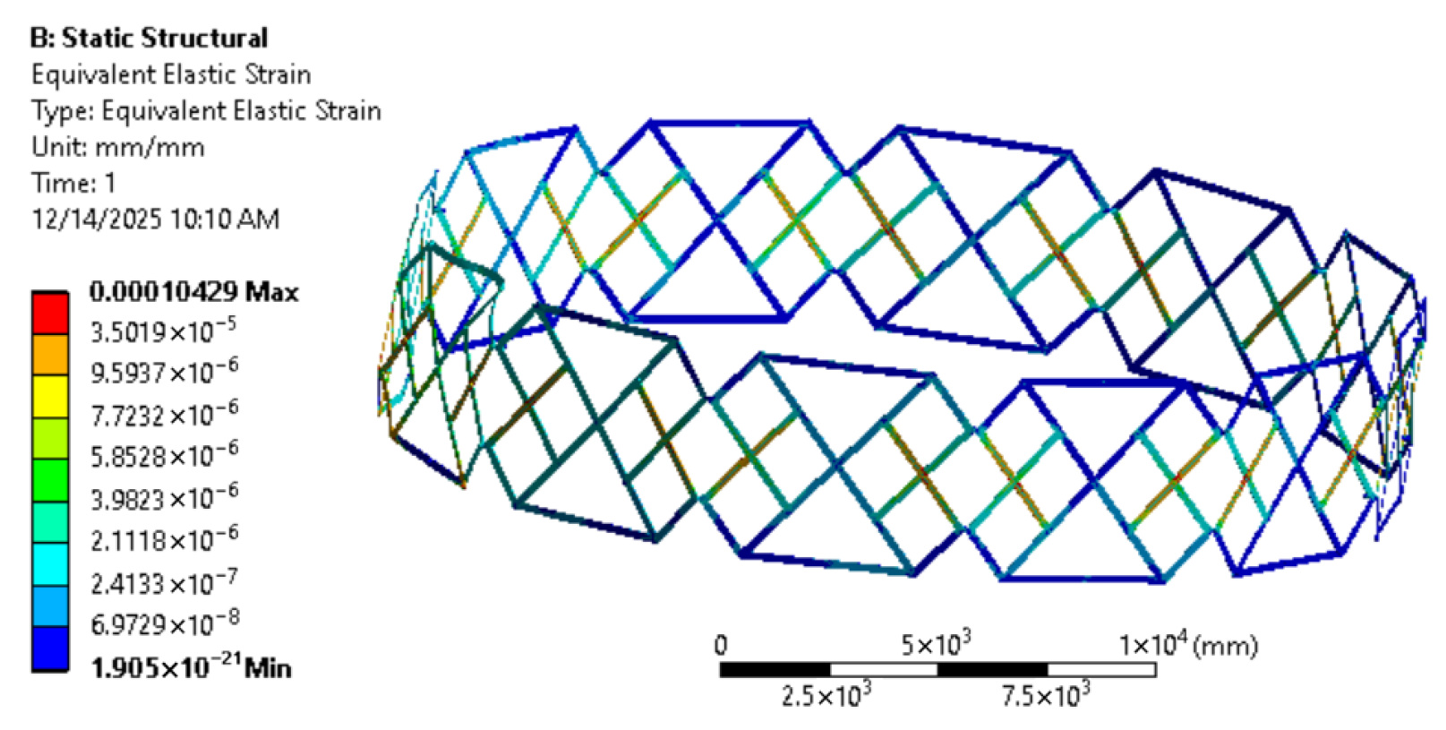
The corresponding strain distribution is shown in Figure 8 for T1100G CFRP. The strain levels remain within elastic limits, confirming the structural safety of the optimized antenna.
The results demonstrate that the optimized antenna maintains geometric stability and structural integrity under combined thermal and mechanical effects.

7. Kinematic Analysis

We analyze the kinematic properties of the new Triple Scissor Deployable Truss Mechanism (TSDAM) using a constraint-based approach to loop-closure. This approach differs from classical Newtonian methods when analyzing the velocity and acceleration of the system because it uses only geometric compatibility conditions imposed by the closed loops to calculate deployment motion. The constraint-based loop-closure formulation is well-suited for deployable mechanisms with synchronized motion and limited DOF. The implementation of a nonlinear kinematic analysis was carried out using a constraint-based formulation of loop-closure equations for the scissor mechanism. The resulting nonlinear equations were solved by numerical methods and iteratively, at every iteration and stage of deployment configuration, to complete an accurate simulation of large deformations and geometric nonlinearities associated with deployable structures.

7.1. Modeling Assumptions

The following assumptions are adopted:
1.
All links are rigid bodies.
2.
Joints are ideal revolute joints without clearance.
3.
The deployment motion is planar and quasi-static.
4.
Each modular unit possesses a single independent degree of freedom.

7.2. Generalized Coordinate

The deployment motion of a modular unit is governed by a single generalized coordinate, defined as the primary scissor opening angle:
q ( t ) = θ ( t )
All remaining joint angles are dependent variables constrained by the geometry of the mechanism. The assumption q ( t ) = θ ( t ) is valid under small deformation conditions where the generalized displacement is directly proportional to the angular rotation. This assumption simplifies the dynamic formulation and is commonly used in reduced-order modeling. However, it may not hold for large nonlinear deformations.

7.3. Geometric Loop-Closure Equations

Consider a triple-scissor unit composed of three interconnected scissor pairs forming a closed kinematic loop. Let the link lengths be denoted by L 1 , L 2 , and L 3 , and the corresponding joint angles by θ , ϕ , and ψ , respectively.
The vector loop-closure condition is expressed as:
r 1 ( θ ) + r 2 ( ϕ ) + r 3 ( ψ ) = 0
Expanding in Cartesian components yields:
L 1 cos θ + L 2 cos ϕ + L 3 cos ψ = 0
L 1 sin θ + L 2 sin ϕ + L 3 sin ψ = 0
These equations define the nonlinear constraint vector:
C ( q ) = C 1 ( θ , ϕ , ψ ) C 2 ( θ , ϕ , ψ ) = 0

7.4. Velocity Analysis

Differentiating the constraint equations with respect to time gives:
d C d t = J ( q ) q ˙ = 0
where J ( q ) is the Jacobian matrix defined as:
J = L 1 sin θ L 2 sin ϕ L 3 sin ψ L 1 cos θ L 2 cos ϕ L 3 cos ψ
This relationship establishes the compatibility requirements for velocity, as well as the relative ratios of velocity at the joint, for deployment.

7.5. Acceleration Analysis

The second derivative of the equation, provides:
J ( q ) q ¨ + J ˙ ( q ) q ˙ = 0
This relationship describes how to compute the accelerations at the joint and also allows one to determine whether the deployment motion is sufficiently smooth and dynamically consistent.

7.6. Validation of the Analytical Approach

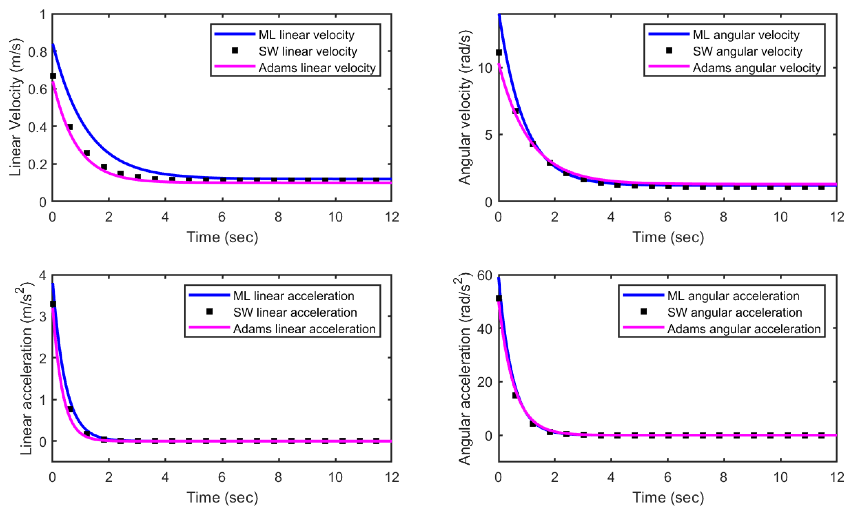
In Figure 9, we can see a comparison between the validation of the analytical (MATLAB-based) model to a 3D multibody dynamic simulation in SolidWorks (SW) and ADAMS, which includes both translational and rotational kinematics. The time histories of linear velocity, angular velocity, linear acceleration, and angular acceleration for the analytical, SW and ADAMS approaches are qualitatively and quantitatively consistent. The analytical model produces a result for linear velocity that parallels the results obtained from SW and ADAMS throughout the simulation duration, accurately representing the rapid decay that occurs in the early transitory phase and the gradual convergence of the response into a steady-state condition. Any discrepancy in the results observed prior to the transient period is likely attributable to factors such as numerical damping, the assumptions made regarding contact modelling and the various discretisation methodologies utilized by commercial multibody software solvers. The angular velocity profiles of the analytical model and SW and ADAMS correlate closely, also reflecting the same initial sharp decline followed by smooth stabilization characteristics. Acceleration response results confirm the validity of the analysis formulations, in that both linear and angular acceleration have large initial peaks that correspond to the dynamic startup phase of the system, before exponentially decaying to zero as the system stabilizes. The results of the analytical predictions are consistent with both the magnitude and decay characteristics of the acceleration prediction outputs of SolidWorks (SW) and ADAMS, and there is minimal deviation between the analytical and numerical calculated results in the transient response region. Overall, there is a close correlation between the analytical predictions and both SW and ADAMS results, indicating the analytical technique’s accuracy, robustness, and ability to simulate complex dynamic behaviour with significantly lower computational cost compared to full-scale multibody simulations.
The difference between analytical and numerical results was quantified, with the maximum difference in velocity being found to be 3.2% and that of acceleration being found to be 4.1% during a transient response. The average difference in velocity and acceleration during a steady state condition was found to be less than 2%.

8. Dynamic Analysis

In order to evaluate a TSDAM’s dynamic characteristics, a flexible multibody formulation is introduced which is based on assumed mode methods and Rayleigh–Ritz approximation methods. This method differs entirely from the classical Lagrangian approach, since deformation fields are approximated directly via acceptable shape functions rather than through classical mathematical equations.

8.1. Analytical Modeling

8.1.1. Flexible Link Modeling

Each scissor link is modeled as an Euler–Bernoulli beam undergoing transverse vibration. The displacement field is approximated as:
w ( x , t ) = k = 1 N ϕ k ( x ) q k ( t )
where ϕ k ( x ) are admissible mode shapes and q k ( t ) are generalized modal coordinates. The Euler–Bernoulli beam theory assumes that plane sections remain plane and normal to the neutral axis, neglecting shear deformation. This theory is widely used for slender beam structures [40].
For the fundamental mode, the following shape function is adopted:
ϕ ( x ) = sin π x L

8.1.2. Kinetic Energy

The kinetic energy of a flexible link is given by:
T = 1 2 0 L ρ A w ˙ ( x , t ) 2 d x
Substituting the assumed mode approximation yields:
T = 1 4 ρ A L q ˙ 2
where ρ is the material density and A is the cross-sectional area.

8.1.3. Potential Energy

The bending strain energy is considered because it dominates the deformation behavior of slender structural elements. It provides an accurate measure of stored elastic energy in the system. The bending strain energy of the link is expressed as:
V = 1 2 0 L E I 2 w x 2 2 d x
where x represents the spatial coordinate along the beam length, E is Young’s modulus, and I is the second moment of area of the beam cross-section.
Substituting the assumed mode function leads to:
V = E I π 4 4 L 3 q 2
The expression in Equation (38) is derived by substituting the assumed mode shape
ϕ ( x ) = sin π x L
into the bending strain energy formulation in Equation (37). The Rayleigh–Ritz method approximates the solution of boundary value problems by minimizing the total potential energy of the system. It is widely used for vibration analysis of continuous systems [34]. Taking the second derivative of the displacement field:
2 w x 2 = π 2 L 2 sin π x L q
Substituting into Equation (37) gives:
V = 1 2 0 L E I π 4 L 4 sin 2 π x L q 2 d x
Using the identity:
0 L sin 2 π x L d x = L 2
we obtain:
V = E I π 4 4 L 3 q 2
which corresponds to Equation (38).

8.1.4. Equation of Motion

Applying the Rayleigh–Ritz condition results in the governing equation:
M q ¨ + K q = 0
where the generalized mass and stiffness coefficients are:
M = 1 2 ρ A L
K = E I π 4 2 L 3

8.1.5. Natural Frequency

The natural frequency of the flexible link is obtained as:
ω = K M
and the corresponding frequency in Hertz is:
f = ω 2 π

8.1.6. System-Level Assembly

For the complete antenna composed of N u modular units, the global mass and stiffness are assembled as:
M global = i = 1 N u M i , K global = i = 1 N u K i
Solving the resulting eigenvalue problem we get 0.09912 Hz which yields the natural frequency of the deployed antenna structure.

8.2. Validation

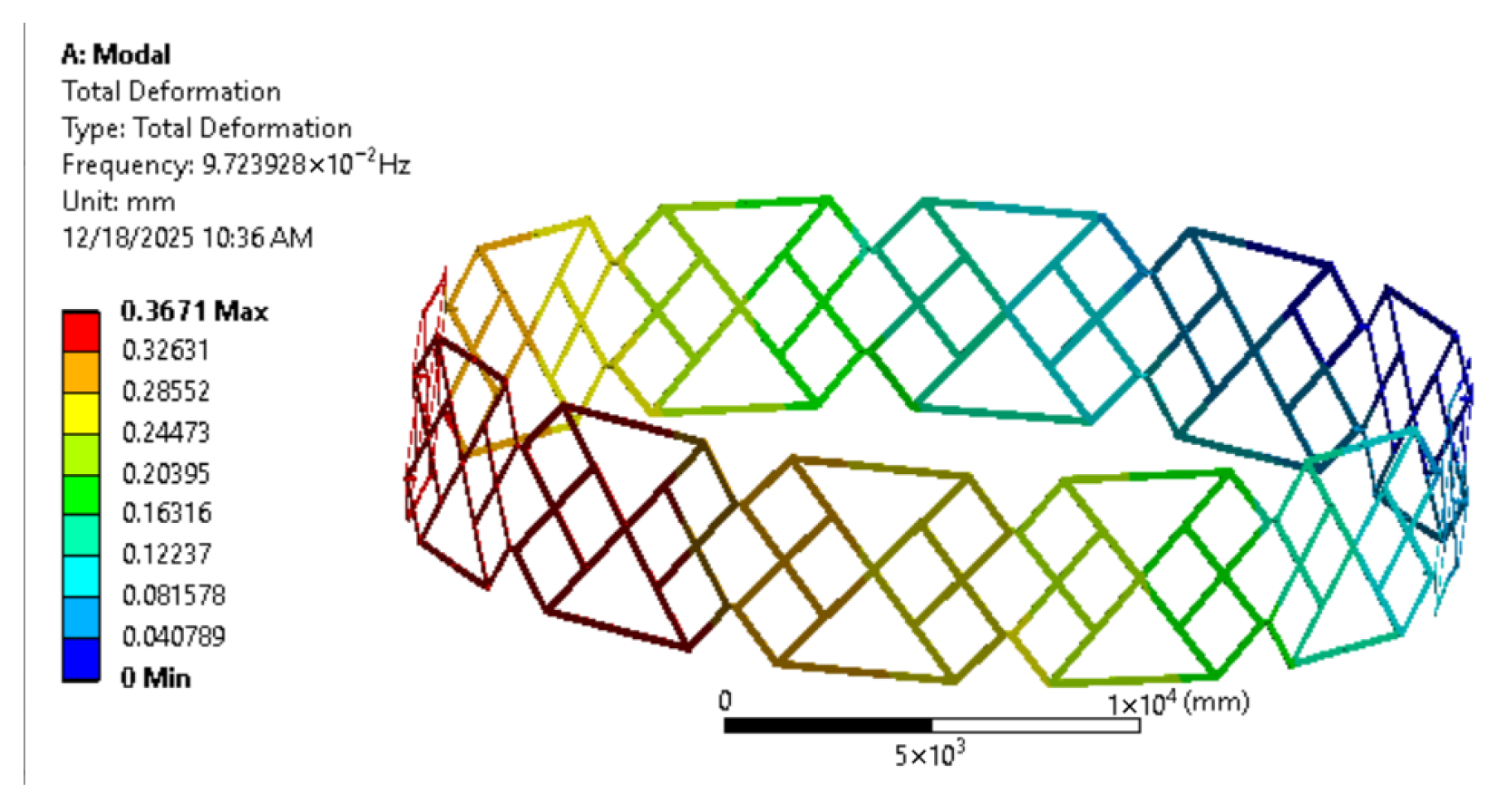
The analytical dynamical model’s response of natural frequencies has been confirmed via numerical simulations in ANSYS Workbench Flow. The first step is to develop a computer-aided design (CAD) model of the deployable space antenna truss in SolidWorks, since it provides the ability to model complex geometries and kinematic constraints that allow deployment. After the SolidWorks model is complete, it is imported into ANSYS Workbench, which is a complete finite element analysis (FEA) solution—the modal analysis is performed on ANSYS Workbench to determine the dynamic properties of the structure. The tools provided by ANSYS Workbench are proven to be accurate and effective for determining the natural frequency of deployable truss systems. The fundamental frequency from the numerical simulation shows a value of 0.09723 Hz (See Figure 10); however, the analytical dynamical model shows a value of 0.09912 Hz.
The percentage error (%) between the analytical and numerical results is calculated as
Percentage Error ( % ) = f analytical f numerical f analytical   ×   100 = 0.09912 0.09723 0.09912   ×   100 1.91 % .
The small percentage error indicates excellent agreement between the analytical and simulation results, thereby validating the proposed dynamical mathematical model and confirming the accuracy and reliability of the analytical frequency prediction for the deployable antenna structure. The results of the dynamic analysis were established using finite element simulations in the ANSYS Workbench. The analytical values correlated well with the results from the numerical analysis, displaying deviation values that fall well within allowable engineering tolerances. Due to the complexity and magnitude of the system, no experimental data were collected; howbeit, the similarity of the analytical and numerical models validates the approach.

9. Comparative Analysis

The basic frequency for the deployable antennas designed for large areas is between 0.01 to 0.1 Hz, because these have large sizes, and they can be LIGHT in weight and have lots of flexibility. The frequency at which we will get 0.09912 Hz as an upper limit in this range shows that we have integrated more rigidity compared to standard designs. Table 5 presents a comparative analysis of the fundamental natural frequencies of various deployable antenna structures reported in the literature alongside the proposed deployable structure. The natural frequency of the double-scissors link truss deployable antenna is compared with those of the AstroMesh antenna, H-double antenna, single-ring deployable truss antenna, and double-ring deployable truss antenna. The AstroMesh antenna exhibits a fundamental natural frequency of 0.012 Hz, while the H-double antenna shows a similarly low-frequency response. In contrast, the proposed double-scissors link deployable antenna demonstrates a significantly higher fundamental natural frequency of 0.09912 Hz. As shown in Table 5, this value lies between the natural frequencies of the H-double antenna (0.012 Hz) and the single-ring deployable truss antenna (0.090 Hz). The comparative results show that, despite differences in how dynamic stiffness was accounted for, proposed mechanism provides an overall improvement in dynamic stiffness, and can still be used at frequencies appropriate for deployable space antenna structures, demonstrating that it meets all structural integrity requirements and dynamic performance requirements.

10. Benchmark Comparison

A benchmark comparison of the proposed triple-scissors deployable truss antenna and representative deployable antenna mechanisms from the literature is summarized in Table 6. Deployable antennas utilizing conventional systems such as AstroMesh reflectors, H-double trusses, and ring-based mechanisms typically have several degrees of freedom, and consequently require distributed or multi-point actuation, which increases both deployment complexity and control requirements. In contrast, a triple-scissors truss architecture that has a single global degree of freedom allows complete and synchronized deployable antennas using only one actuated input. The triple-scissors truss architecture considerably simplifies the deployment mechanism. Dynamic performance analysis shows that the fundamental natural frequency of the proposed antenna is 0.09912 Hz, significantly greater than that of the AstroMesh reflector (0.012 Hz) and of the H-double truss antenna (0.021 Hz), indicating higher overall stiffness. The double-ring truss antenna has a somewhat higher frequency (0.101 Hz) than the proposed design, but due to smaller aperture size and a more complicated multi-degree-of-freedom configuration. Additionally, the proposed antenna has a comparable frequency response as the double-ring truss, but has a significantly larger (26.8 m) aperture size, demonstrating greater scalability, without sacrificing dynamic stability. The new truss design has a storage ratio of 8.21, which demonstrates excellent packaging efficiency compared to other deployable mechanisms on the market and is significantly better than single and double ring truss antennas. The improved storage efficiency is the result of the use of multiple layers of scissor elements to allow for compact folding while also maintaining structural integrity throughout. The comparison shows that this new antenna design provides an equal combination of dynamic stiffness, scalability of large apertures, compact stowing of the antenna, ease of actuation during deployment, thus presenting this antenna configuration as an attractive choice for future applications of large-aperture space antennas.
A review of the traditional deployable antennas shows that typical traditional designs, like single ring and umbrella type mechanisms, often have numerous degrees of freedom and complex actuation systems that typically lead to much longer deployment times (100–140 s), as well as lower structural stiffness (with most have fundamental mode frequencies below 0.09 Hz). The proposed triple scissor deployable antennas deploy via a single degree of freedom, which provides for reduced complexity of actuation and will also allow for a very much higher degree of stiffness for the optimized structure (indicated by a higher natural frequency and reduced structural deformation when thermally loaded). This demonstrates that the proposed design has been shown to meet both structural efficiency and operational simplicity.


11. Conclusions

The novel Triple-Scissor Deployable Antenna Mechanism presented in this paper addresses a number of pressing issues associated with the deployment synchronization, stiffness, scalability and thermal robustness of large-aperture antennas for space applications. The Modular Architecture of the Proposed System Allows For A Single-Degree-of-Freedom Deployment of the Antenna Mechanism, while still maintaining structural integrity and geometrical compatibility of the entire antenna assembly. Utilizing Fuzzy Algebra-Based Material Selection and Fuzzy Geometry Optimization, An Optimized Antenna Configuration with a diameter of 26.8 m and a total mass of 128.4 kg was produced with a feasibility index of 0.91. The fundamental natural frequency of the Optimized Structure is 0.09912 Hz, indicating increased dynamic stiffness in comparison with the traditional deployable antenna designs. Validation of the design was accomplished with Multibody and Finite Element Simulations, which produced kinematic and dynamic prediction errors of less than 2%. Thermo-structural analysis of CFRP-based configurations shows that CFRP offers the best thermal stability and deformation resistance due to enhanced thermal stability and deformation resistance in extreme temperature variations. With the use of uncertainty aware fuzzy optimization and rigorous analytical validation, this TSDAM represents an effective and scalable solution for the development of future large deployable antenna systems for space. Future work will include experimental prototyping, active deployment control, and on-orbit performance assessment.

Future Work

The deployment of the antenna structure changes the mass distribution and inertia tensor of the satellite, which will affect the dynamics of the satellite’s attitude. While the focus of this study is on the performance of the antenna structure and the performance of the deployment, it is noted that the change in inertia may contribute to how the attitude control system will behave. Future work will include conducting an integration of an analysis of the effects of the previous paragraph on the deployment performance of the antenna upon the associated attitude.

Author Contributions

Conceptualization, M.A. and A.Z.A.; methodology, M.A. and A.Z.A.; software, M.A.; validation, M.O., A.Z.A. and L.K.; formal analysis, M.O.; investigation, M.A.; resources, M.O.; data curation, L.K.; writing—original draft preparation, M.A. and A.Z.A.; writing—review and editing, M.O. and L.K.; visualization, M.O.; supervision, A.Z.A.; project administration, L.K.; funding acquisition, M.O. All authors have read and agreed to the published version of the manuscript.

Funding

This Project was funded by the Deanship of Scientific Research (DSR) at King Abdulaziz University, Jeddah, Saudi Arabia under grant no. (IPP: 1282-305-2025). The authors, therefore, acknowledge with thanks DSR for technical and financial support.

Institutional Review Board Statement

Not applicable.

Informed Consent Statement

Not applicable.

Data Availability Statement

Data can be made available on reasonable request.

Conflicts of Interest

The authors declare no conflicts of interest.

References

  1. Escrig, F. Expandable space structures. Int. J. Space Struct. 1985, 1, 79–91. [Google Scholar] [CrossRef]
  2. Furuya, H.; Higashiyama, K. Dynamics of closed linked variable geometry truss manipulators. Acta Astronaut. 1995, 36, 251–259. [Google Scholar] [CrossRef]
  3. Arduini, C. An approach to the dynamics of modular repetitive structures. Acta Astronaut. 1985, 12, 661–666. [Google Scholar] [CrossRef]
  4. Nagaraj, B.P.; Nataraju, B.S.; Ghosal, A. Dynamics of a two-link flexible system undergoing locking: Mathematical modelling and comparison with experiments. J. Sound Vib. 1997, 207, 567–589. [Google Scholar] [CrossRef]
  5. Florio, F.A.; Josloff, A.T. Thermo/structural analysis of a large flexible paraboloid antenna. J. Spacecr. Rocket. 1968, 5, 1417–1424. [Google Scholar] [CrossRef]
  6. You, Z.; Pellegrino, S. Cable-stiffened pantographic deployable structures part 2: Mesh reflector. AIAA J. 1997, 35, 1348–1355. [Google Scholar] [CrossRef]
  7. Amer, T.S.; El-Sabaa, F.M.; Zakria, S.K.; Galal, A.A. The stability of 3-DOF triple-rigid-body pendulum system near resonances. Nonlinear Dyn. 2022, 110, 1339–1371. [Google Scholar] [CrossRef]
  8. Amer, T.S.; El-Sabaa, F.M.; Moatimid, G.M.; Zakria, S.K.; Galal, A.A. On the stability of a 3DOF vibrating system close to resonances. J. Vib. Eng. Technol. 2024, 12, 6297–6319. [Google Scholar] [CrossRef]
  9. Park, F.C.; Bobrow, J.E.; Ploen, S.R. A Lie group formulation of robot dynamics. Int. J. Robot. Res. 1995, 14, 609–618. [Google Scholar] [CrossRef]
  10. Legnani, G.; Casolo, F.; Righettini, P.; Zappa, B. A homogeneous matrix approach to 3D kinematics and dynamics—I. Theory. Mech. Mach. Theory 1996, 31, 573–587. [Google Scholar] [CrossRef]
  11. Dasgupta, B.; Choudhury, P. A general strategy based on the Newton–Euler approach for the dynamic formulation of parallel manipulators. Mech. Mach. Theory 1999, 34, 801–824. [Google Scholar] [CrossRef]
  12. Bi, Z.M.; Kang, B. An inverse dynamic model of over-constrained parallel kinematic machine based on Newton–Euler formulation. J. Dyn. Syst. Meas. Control 2014, 136, 041001. [Google Scholar] [CrossRef]
  13. Shi, P.; McPhee, J. Dynamics of flexible multibody systems using virtual work and linear graph theory. Multibody Syst. Dyn. 2000, 4, 355–381. [Google Scholar] [CrossRef]
  14. Arsenault, M.; Gosselin, C.M. Kinematic, static and dynamic analysis of a planar 2-DOF tensegrity mechanism. Mech. Mach. Theory 2006, 41, 1072–1089. [Google Scholar] [CrossRef]
  15. Shi, H.; Yang, B.; Thomson, M.; Fang, H. Coupled elastic-thermal dynamics of deployable mesh reflectors. In Proceedings of the 52nd AIAA/ASME/ASCE/AHS/ASC Structures, Structural Dynamics and Materials Conference 19th AIAA/ASME/AHS Adaptive Structures Conference, Denver, CO, USA, 4–7 April 2011; p. 2001. [Google Scholar]
  16. Vu, K.K.; Liew, J.R.; Anandasivam, K. Deployable tension-strut structures: Structural morphology study and alternative form creations. Int. J. Space Struct. 2006, 21, 149–164. [Google Scholar] [CrossRef]
  17. Eberhard, P.; Schiehlen, W. Computational dynamics of multibody systems: History, formalisms, and applications. J. Comput. Nonlinear Dynam. 2006, 1, 3–12. [Google Scholar] [CrossRef]
  18. Jorgensen, J.; Louis, E.; Hinkle, J.; Silver, M.; Zuckermandel, B.; Enger, S. Dynamics of an elastically deployable solar array: Ground test model validation. In Proceedings of the 46th AIAA/ASME/ASCE/AHS/ASC Structures, Structural Dynamics and Materials Conference, Austin, TX, USA, 18–21 April 2005; p. 1942. [Google Scholar]
  19. Shen, Y.; Montminy, S.; Zheng, W. Design and dynamical analysis of a SAR membrane antenna deployable structure. In Proceedings of the ASME International Mechanical Engineering Congress and Exposition, Chicago, IL, USA, 5–10 November 2006; Volume 47659, pp. 613–619. [Google Scholar]
  20. Na, K.S.; Kim, J.H. Deployment of a multi-link flexible structure. J. Sound Vib. 2006, 294, 298–313. [Google Scholar] [CrossRef]
  21. Soykasap, O. Deployment analysis of a self-deployable composite boom. Compos. Struct. 2009, 89, 374–381. [Google Scholar] [CrossRef]
  22. Cui, D.; Yan, S.; Guo, X.; Chu, F. An overview of dynamics modeling of inflatable solar array. Energy Procedia 2012, 14, 1967–1972. [Google Scholar] [CrossRef][Green Version]
  23. Katsumata, N.; Natori, M.C.; Yamakawa, H. Analysis of dynamic behaviour of inflatable booms in zigzag and modified zigzag folding patterns. Acta Astronaut. 2014, 93, 45–54. [Google Scholar] [CrossRef]
  24. Xu, Y.; Guan, F.; Xu, X.; Wang, H.; Zheng, Y. Development of a Novel Double-Ring Deployable Mesh Antenna. Int. J. Antennas Propag. 2012, 2012, 375463. [Google Scholar] [CrossRef]
  25. Dai, L.; Guan, F.; Guest, J.K. Structural optimization and model fabrication of a double-ring deployable antenna truss. Acta Astronaut. 2014, 94, 843–851. [Google Scholar] [CrossRef]
  26. Qi, X.; Huang, H.; Li, B.; Deng, Z. A large ring deployable mechanism for space satellite antenna. Aerosp. Sci. Technol. 2016, 58, 498–510. [Google Scholar] [CrossRef]
  27. Han, B.; Xu, Y.; Yao, J.; Zheng, D.; Li, Y.; Zhao, Y. Design and analysis of a scissors double-ring truss deployable mechanism for space antennas. Aerosp. Sci. Technol. 2019, 93, 105357. [Google Scholar] [CrossRef]
  28. Sun, Z.; Yang, D.; Duan, B.; Kong, L.; Zhang, Y. Structural design, dynamic analysis, and verification test of a novel double-ring deployable truss for mesh antennas. Mech. Mach. Theory 2021, 165, 104416. [Google Scholar] [CrossRef]
  29. Sun, Z.; Zhang, Y.; Yang, D. Structural design, analysis, and experimental verification of an H-style deployable mechanism for large space-borne mesh antennas. Acta Astronaut. 2021, 178, 481–498. [Google Scholar]
  30. Jinwei, G.; Yongsheng, Z.; Yundou, X.; Yongjie, L.; Jiantao, Y. Design and analysis of truss deployable antenna mechanism based on a novel symmetric hexagonal profile division method. Chin. J. Aeronaut. 2021, 34, 87–100. [Google Scholar] [CrossRef]
  31. Meng, Q.; Liu, X.J.; Xie, F. Structure design and kinematic analysis of a class of ring truss deployable mechanisms for satellite antennas based on novel basic units. Mech. Mach. Theory 2022, 174, 104881. [Google Scholar] [CrossRef]
  32. Ross, T.J. Fuzzy Logic with Engineering Applications; John Wiley & Sons: Hoboken, NJ, USA, 2005. [Google Scholar]
  33. Banerjee, A. Flexible Multibody Dynamics: Efficient Formulations with Applications; CRC Press: Boca Raton, FL, USA, 2022. [Google Scholar]
  34. Meirovitch, L. Computational Methods in Structural Dynamics; Springer Science & Business Media: Dordrecht, The Netherlands, 1980; Volume 5. [Google Scholar]
  35. Gantes, C.J. Deployable Structures: Analysis and Design; Computational Mechanics, Inc.: Billerica, MA, USA, 2001. [Google Scholar]
  36. Tibert, G. Deployable Tensegrity Structures for Space Applications. Doctoral Dissertation, KTH Royal Institute of Technology, Stockholm, Sweden, 2002. [Google Scholar]
  37. Razmara, N.; Kohli, D.; Dhingra, A.K. On the degrees of freedom of motion of planar-spatial mechanisms. In Proceedings of the International Design Engineering Technical Conferences and Computers and Information in Engineering Conference, Baltimore, MD, USA, 10–13 September 2000; American Society of Mechanical Engineers: New York, NY, USA, 2000; Volume 35203, pp. 1135–1141. [Google Scholar]
  38. Zadeh, L.A. Fuzzy sets. Inf. Control 1965, 8, 338–353. [Google Scholar] [CrossRef]
  39. Rao, S.S. Engineering Optimization: Theory and Practice; John Wiley & Sons: Hoboken, NJ, USA, 2019. [Google Scholar]
  40. Timoshenko, S. History of Strength of Materials: With a Brief Account of the History of Theory of Elasticity and Theory of Structures; Courier Corporation: Chelmsford, MA, USA, 1983. [Google Scholar]
Figure 1. Geometric layout of single unit of TSDAM.
Mca 31 00052 g001
Figure 2. Development of the modular unit for novel space antenna mechanism (a) single scissor link, (b) symmetric side scissors links, (c) supporting links, and (d) horizontal links.
Mca 31 00052 g002
Figure 3. Stowed configuration for modular unit of TSDAM.
Mca 31 00052 g003
Figure 4. Cycle of operation for TSDAM assembly.
Mca 31 00052 g004
Figure 5. Zoomed in view of the joints involved in deployment of TSDAM.
Mca 31 00052 g005
Figure 6. Fuzzy membership functions for thermal survivability.
Mca 31 00052 g006
Figure 7. Total deformation of the optimized antenna for different materials. (a) 4340 Steel; (b) Al-7075; (c) Ti-6Al-4V; (d) M55J CFRP; (e) T1100G CFRP.
Mca 31 00052 g007
Figure 8. Thermally induced strain distribution.
Mca 31 00052 g008
Figure 9. Linear velocity, angular velocity, linear acceleration, angular acceleration.
Mca 31 00052 g009
Figure 10. Natural frequency.
Mca 31 00052 g010
Table 1. Comparison of different antenna deployment mechanisms.
AntennaApertureNo. of UnitsDeployment Time (s)Full Cycle
IntermediateComplete
Triple scissor25 m122653102 s
Single ring25 m2450140
Double ring5 m1860102
Table 2. Material properties used in analysis.
MaterialDensityYMCTETS
4340 Steel7850210121080
Al-707528107123572
Ti-6Al-4V44301139900
M55J CFRP1800290∼0.51600
T1100G CFRP1600324∼0.21800
Table 3. Detailed fuzzy decision results for material alternatives.
Material D + D CC i Final Score
T1100G CFRP0.1560.7820.8340.8838
M55J CFRP0.2010.7160.7780.8446
Ti-6Al-4V0.2440.6450.7250.8075
Al-70750.2910.6010.6740.7718
4340 Steel0.3340.5740.6320.7424
Table 4. Link lengths for antenna radius 13.4 m.
L 1 L 2 L 3 L 4 L 5 L 6 L 7
7.127.122.302.302.302.303.56
L 8 L 9 L 10 L 11 L 12 L 13 L 14
3.563.563.561.781.781.781.78
Table 5. Comparative analysis with already existing antennas.
Sr. #AntennaFrequency
1.Astro Mesh0.012
2.H-Double0.021
3.Single Ring0.090
4.Double Ring0.101
5.Triple Scissor0.09912
Table 6. Benchmark comparison of deployable antenna mechanisms.
AntennaDoFApertureFrequencyStorage RatioActuation
[27]>15.0 m0.0217.94Multiple
[26]>113.0 m0.0905.21Multiple
[24]>115.0 m0.1015.21Multiple
Proposed126.8 m0.099128.21Single
Disclaimer/Publisher’s Note: The statements, opinions and data contained in all publications are solely those of the individual author(s) and contributor(s) and not of MDPI and/or the editor(s). MDPI and/or the editor(s) disclaim responsibility for any injury to people or property resulting from any ideas, methods, instructions or products referred to in the content.