Article

Secure Communication of Electric Drive System Using Chaotic Systems Base on Disturbance Observer and Fuzzy Brain Emotional Learning Neural Network

School of Electrical and Electronic Engineering, Hanoi University of Science and Technology, Dai Co Viet, Ha Noi 11615, Vietnam
*
Author to whom correspondence should be addressed.
Math. Comput. Appl. 2025, 30(4), 73; https://doi.org/10.3390/mca30040073
Submission received: 20 May 2025 / Revised: 7 July 2025 / Accepted: 10 July 2025 / Published: 14 July 2025
(This article belongs to the Special Issue Applied Optimization in Automatic Control and Systems Engineering)

Abstract

This paper presents a novel wireless control framework for electric drive systems by employing a fuzzy brain emotional learning neural network (FBELNN) controller in conjunction with a Disturbance Observer (DO). The communication scheme uses chaotic system dynamics to ensure data confidentiality and robustness against disturbance in wireless environments. To be applied to embedded microprocessors, the continuous-time chaotic system is discretized using the Grunwald–Letnikov approximation. To avoid the loss of generality of chaotic behavior, Lyapunov exponents are computed to validate the preservation of chaos in the discrete-time domain. The FBELNN controller is then developed to synchronize two non-identical chaotic systems under different initial conditions, enabling secure data encryption and decryption. Additionally, the DOB is introduced to estimate and mitigate the effects of bounded uncertainties and external disturbances, enhancing the system’s resilience to stealthy attacks. The proposed control structure is experimentally implemented on a wireless communication system utilizing ESP32 microcontrollers (Espressif Systems, Shanghai, China) based on the ESP-NOW protocol. Both control and feedback signals of the electric drive system are encrypted using chaotic states, and real-time decryption at the receiver confirms system integrity. Experimental results verify the effectiveness of the proposed method in achieving robust synchronization, accurate signal recovery, and a reliable wireless control system. The combination of FBELNN and DOB demonstrates significant potential for real-time, low-cost, and secure applications in smart electric drive systems and industrial automation.

1. Introduction

The fuzzy inference system (FIS) mimics human reasoning and has demonstrated effectiveness across a wide range of domains. While conventional control system design required detailed mathematical models, modern fuzzy systems employ inference rules that enable control without exact system representations [1,2]. This approach has been further advanced in recent literature, where FIS-based controllers provide adaptability and robustness for nonlinear, uncertain, and chaotic environments [3,4,5]. Neural networks (NNs) offer benefits such as parallel computation, error resilience, generalization, and strong approximation capabilities, making them highly suitable for system identification and control applications [6,7]. Integrating FIS with neural networks leads to fuzzy neural networks (FNNs), which have been successfully implemented in a variety of regulation mechanisms [8,9,10,11,12,13].
Building on inspiration from the human brain’s structure and neural interconnectivity, Marr introduced a theoretical framework to describe cerebellar information processing [14]. The cerebellar model articulation controller (CMAC), originally proposed by Albus, emulates cerebellar functions and provides a learning mechanism for adaptive control [15]. Characterized by sparse associative memory and overlapping receptive fields, CMACs efficiently address the complexity and scalability issues in conventional neural networks. As a result, CMACs have seen extensive application in feedback control for complex dynamic systems [16,17]. Extensions such as fuzzy CMACs further enhance performance by combining fuzzy inference with the CMAC structure [18,19,20,21].
Despite these advances, emotional processing has been largely overlooked in NNs and CMACs. LeDoux’s work established that the amygdala is responsible for forming associations between stimuli and emotional responses [22]. The human brain comprises both sensory (orbitofrontal cortex) and emotional (amygdala) neural networks, which interact synergistically to achieve adaptive learning and response [23,24]. While sensory networks facilitate autonomous learning, emotional networks react to external stimuli and modulate the sensory response. The brain emotional learning controller (BELC) architecture captures this interaction by integrating outputs from both networks. Inspired by neurophysiological findings, intelligent emotional learning algorithms were developed [25], and BELC has subsequently found application in intelligent control systems [26,27,28]. Notably, while both CMAC and BELC are biologically inspired, only BELC incorporates an explicit emotional network, enabling adaptive weighting of sensory information based on the significance of stimuli, a mechanism critical for robust learning in uncertain environments [5,11,29].
Recent developments have further demonstrated the effectiveness of integrating fuzzy inference, neural, and emotional learning algorithms in robust control frameworks. Advanced architectures, such as the fuzzy brain emotional learning controller (FBELC), combine the rule-based reasoning of FIS and the adaptive learning of BELC, resulting in controllers capable of addressing the challenges of nonlinear, time-varying, and chaotic systems [3,4,5,24,30,31]. The inclusion of Disturbance Observer-Based (DOB) mechanisms has significantly improved the capacity to estimate and compensate for external disturbances and system uncertainties, as evidenced in secure communication and industrial control applications [3,4,29,32,33,34,35,36,37,38,39,40]. Recent studies have also highlighted the potential of observer-based control and fractional-order adaptive mechanisms to enhance the robustness and synchronization performance of chaotic secure communication systems [41,42,43,44].
Motivated by the limitations of current intelligent controllers such as CMACs and FNNs—which often lack explicit emotional intelligence—this study seeks to bridge the gap by integrating fuzzy inference and brain emotional learning into a unified control framework. The resulting FBELC architecture not only leverages fuzzy rule inference for decision-making but also incorporates emotional neural processing to achieve more adaptive and robust learning, particularly in nonlinear and dynamic environments.
The primary contributions of this work are as follows:
(1)
Development of a novel FBELC structure that uniquely combines fuzzy logic and emotional intelligence within a single control architecture;
(2)
Integration of a DO to enhance robustness against external perturbations and uncertainties;
(3)
Systematic analysis and experimental validation of the proposed controller on nonlinear dynamic systems, including comparative studies with conventional methods to highlight the FBELC’s advantages in adaptability, disturbance rejection, and effectiveness [3,5,11,16,17,18,19,20,21,22,23,24,25,26].
The originality of this work lies in the development of the FBELC, which synthesizes fuzzy inference and emotional learning in a cohesive control strategy. Unlike traditional models, the FBELC evaluates the significance of environmental stimuli via its emotional network, directly influencing sensory processing and control actions. This integrated approach provides a more comprehensive and adaptive learning mechanism, marking a substantial advancement in the field of intelligent control systems.

2. Mathematical Concept

In this section, the mathematical model of the chaotic system and the operation of the FBELNN are presented. First, the original chaotic system in [10] is converted into the discrete-time system. Second, the operation of the neural network and its stability analysis are given.

2.1. Mathematical Modeling of Chaotic System

This paper reuses the model of the chaotic system in [10]. The original chaotic system is:
x ˙ ( Γ ) = a ( y ( Γ ) x ( Γ ) ) y ˙ ( Γ ) = c y ( Γ ) x ( Γ ) z ( Γ ) + w ( Γ ) z ˙ ( Γ ) = y ( Γ ) x ( Γ ) b z ( Γ ) w ˙ ( Γ ) = z ( Γ ) d w ( Γ )
where a = 20, b = 5, c = 10 and d = 1.5, respectively. The Grunwald–Letnikov approximation method in [45] was used to convert system (1) to the discrete time domain, and system (1) is then equal to:
x ( ) = x ( 1 ) + h a ( y ( 1 ) x ( 1 ) ) y ( ) = y ( 1 ) + h ( c y ( 1 ) x ( 1 ) z ( 1 ) + w ( 1 ) ) z ( ) = z ( 1 ) + h ( y ( 1 ) x ( 1 ) b z ( 1 ) ) w ( ) = w ( 1 ) + h ( z ( 1 ) d w ( 1 ) )
where is step time number and h = 0.001 is step time. The Jacobian matrix is then calculated by:
J = 1 a h a h 0 0 h z 1 + c h h x h h y h x 1 b h 0 0 0 h 1 d h
The discrete time chaotic system (2) consists of three equivalent points
E 1 = 0 0 0 0 ,
E 2 = 2.0753 . 10 13 4.1961 . 10 7 j 1.0169 . 10 11 + 2.0561 . 10 5 j 2.0857 . 10 16 + 4.2172 . 10 10 j 2.0889 . 10 19 4.2235 . 10 13 j
and
E 3 = 2.0753 . 10 13 + 4.1961 . 10 7 j 1.0169 . 10 11 2.0561 . 10 5 j 2.0857 . 10 16 4.2172 . 10 10 j 2.0889 . 10 19 + 4.2235 . 10 13 j .
The eigenvalues with E 1 are λ E 1 1 = 0.98 , λ E 1 2 = 1.01 , λ E 1 3 = 0.98 and λ E 1 4 = 0.995 . The eigenvalues with E 2 are λ E 2 1 = 0.98 , λ E 2 2 = 0.995 , λ E 2 3 = 0.9985 , λ E 24 = 1.01 . The eigenvalues with E 3 are λ E 3 1 = 0.98 , λ E 3 2 = 0.995 , λ E 3 3 = 0.9985 , λ E 34 = 1.01 . The Lyapunov exponents are L 1 = 1.9985 , L 2 = 0.0495 , L 3 = 0.4276 and L 4 = 16.7848 . The Lyapunov exponents are shown in Figure 1.
The converted chaotic system in the discrete time domain retains the original characteristics of the chaos system. Therefore, the secure communication of chaotic systems in digital devices is reliable and implementable.

2.2. Problem Formulation

In the secure communication system (SCS), the chaotic system (2) can be used for both master and slave with different initial conditions. Therefore, the slave system can be:
x m ( ) = x m ( 1 ) + h a ( y m ( 1 ) x s ( 1 ) ) + Δ x m y m ( ) = y m ( 1 ) + h ( c y m ( 1 ) x m ( 1 ) z m ( 1 ) + w m ( 1 ) ) + Δ y m z m ( ) = z m ( 1 ) + h ( y m ( 1 ) x m ( 1 ) b z m ( 1 ) ) + Δ z m w m ( ) = w m ( 1 ) + h ( z m ( 1 ) d w m ( 1 ) ) + Δ w m
where Δ x m , Δ y m , Δ z m and Δ w m are uncertainties of the master.
Assumption 1.
These uncertainties and disturbances are bounded as follows: Δ x m < ξ 1 , Δ y m < ξ 2 , Δ y m < ξ 3 , Δ w m < ξ 4 with ξ 1 , ξ 2 , ξ 3 , ξ 4 are positively defined.
The slave system is:
x s ( ) = x s ( 1 ) + h a ( y s ( 1 ) x s ( 1 ) ) + Δ x s + d x ( 1 ) + u x ( 1 ) y s ( ) = y s ( 1 ) + h ( c y s ( 1 ) x s ( 1 ) z s ( 1 ) + w m ( 1 ) ) + Δ y s + d y ( 1 ) + u y ( 1 ) z s ( ) = z s ( 1 ) + h ( y s ( 1 ) x s ( 1 ) b z s ( 1 ) ) + Δ z s + d z ( 1 ) + u z ( 1 ) w s ( ) = w s ( 1 ) + h ( z s ( 1 ) d w s ( 1 ) ) + Δ w s + d w ( 1 ) + u w ( 1 )
where Δ x s , Δ y s , Δ z s , and Δ w s are uncertainties of the slave. d x , d y , d z , and d w are the disturbances on public channels.
Assumption 2.
These uncertainties and disturbances are bounded as follows: Δ x s < ξ 1 ; Δ y s < ξ 2 ; Δ z s < ξ 3 and Δ v s < ξ 4 with ξ 1 ; ξ 2 ; ξ 3 and ξ 4 are positively defined.
Remark 1.
Assumptions 1 and 2 merely require that the lumped uncertainties and channel disturbances stay within finite, known bounds. This bounded-disturbance premise is standard in secure chaotic-control literature and is exactly the condition needed for the Lyapunov inequalities (51)–(54) to be negative-definite. A closely related study in [27] adopted the same bounded-uncertainty hypothesis and experimentally achieved asymptotic convergence, confirming the practical effectiveness of these assumptions. The tracking errors of master and slave are
e x ( 1 ) = x m ( 1 ) x s ( 1 ) e y ( 1 ) = y m ( 1 ) y s ( 1 ) e z ( 1 ) = z m ( 1 ) z s ( 1 ) e w ( 1 ) = w m ( 1 ) w s ( 1 )
Therefore,
e x ( ) = e x ( 1 ) + h a ( e y ( 1 ) e x ( 1 ) ) + Δ x m Δ x s d x ( 1 ) u x ( 1 ) e y ( ) = e y ( 1 ) + h ( c e y ( 1 ) x m ( 1 ) z m ( 1 ) + x s ( 1 ) z s ( 1 ) + e w ( 1 ) ) + Δ y m Δ y s d y ( 1 ) u y ( 1 ) e z ( ) = e z ( 1 ) + h ( y m ( 1 ) x m ( 1 ) y s ( 1 ) x s ( 1 ) b e z ( 1 ) ) + Δ z m Δ z s + d z ( 1 ) + u z ( 1 ) e w ( ) = e w ( 1 ) + h ( e z ( 1 ) d e w ( 1 ) ) + Δ w m Δ w s d w ( 1 ) u w ( 1 )
Equation (7) can be converted to
e ( ) = A e ( 1 ) + f ( 1 ) + Δ ( 1 ) + d ( 1 ) + u ( 1 )
where e ( ) = e x ( ) e y ( ) e z ( ) e w ( ) , e ( 1 ) = e x ( 1 ) e y ( 1 ) e z ( 1 ) e w ( 1 ) , f ( 1 ) = f x ( 1 ) ) f y ( 1 ) f z ( 1 ) f w ( 1 ) , Δ ( 1 ) = Δ x m Δ x s Δ y m Δ y s Δ z m Δ z s Δ w m Δ w s , d ( 1 ) = d x ( 1 ) d y ( 1 ) d z ( 1 ) d w ( 1 ) , and u ( 1 ) = u x ( 1 ) u y ( 1 ) u z ( 1 ) u w ( 1 ) , with f x ( 1 ) = h a ( e y ( 1 ) e x ( 1 ) ) , f y ( 1 ) = h ( c e y ( 1 ) x m ( 1 ) z m ( 1 ) + x s ( 1 ) z s ( 1 ) + e w ( 1 ) ) ,   f z ( 1 ) = h ( y m ( 1 ) x m ( 1 ) y s ( 1 ) x s ( 1 ) b e z ( 1 ) ) , and f w ( 1 ) = h ( e z ( 1 ) d e w ( 1 ) ) . In this case, the control input of Equation (8) is as follows
u ( 1 ) = A e ( 1 ) f ( 1 ) Δ ( 1 ) d ( 1 ) + K e ( 1 )
Herein, the d ( 1 ) and K e ( 1 ) are unable to be known. The DOB can be used to estimated these values. Therefore, Equation (8) becomes
e ( ) = K e ( 1 )
Then, the errors will come to equivalent points if the matrix K is Hurwitz. However, the achievements of the disturbances and uncertainties are unreliable. Therefore, this paper designs a learning neural network to achieve a simplified control design that remains robust against parameter variations in both master and slave systems while mitigating external disturbances.

2.3. Fuzzy Brain Emotional Learning Controller

The aim of the FBELC is to ensure robustness in the steady-state area. The structure of the designed controller is shown in Figure 2.
The sensory input layer is designed with conjunctions as follows: If I 1 ( 1 ) is Λ 1 j ( 1 ) , I 2 ( 1 ) is Λ 2 j ( 1 ) , and I m ( 1 ) is Λ m j ( 1 ) the a ( 1 ) = v i j ( 1 ) , where v i j ( 1 ) is the amygdala weight.
The emotional neural network is as follows: If I 1 ( 1 ) is Λ 1 j ( 1 ) , I 2 ( 1 ) is Λ 2 j ( 1 ) , and I m ( 1 ) is Λ m j ( 1 ) the o ( 1 ) = w i j ( 1 ) , where w i j ( 1 ) is prefrontal weight. The weights are selected in order to satisfy the conditions of
Δ v ( 1 ) = α [ s i j × ( m a x [ o , d i ( 1 ) a ( 1 ) ] )
and
Δ w ( 1 ) = β [ s i j × ( u n e u r a l ( 1 ) d i ( 1 ) )
where
d i ( 1 ) = b i × I i + c × u n e u r a l ( 1 )
As shown in Figure 1, the input layer is
I ( 1 ) = [ I 1 ( 1 ) , I 2 ( 1 ) , I m ( 1 ) ] T
s i j is a type II Gausian function with
s i j ( 1 ) = e x p ( ( I i ( 1 ) ϵ i j ) 2 δ i 2 j ( I i ( 1 ) λ i j ) 2 γ i 2 j )
where ϵ i j and λ i j are the means of the Gauss function, and δ i 2 j and γ i 2 j are variances of the Gauss function. The amygdala weight is
v j a ( 1 ) = [ v 1 a ( 1 ) , . . , v m a ( 1 ) ] T
and
v j b ( 1 ) = [ v 1 b ( 1 ) , . . , v m b ( 1 ) ] T
Prefrontal weights are
w j a ( 1 ) = [ w 1 a ( 1 ) , . . , w m a ( 1 ) ] T
and
w j b ( 1 ) = [ w 1 b ( 1 ) , . . , w m b ( 1 ) ] T
The control value of this controller is defined as follows:
u ( 1 ) = a ( 1 ) o ( 1 )
where i = 1 n and j = 1 m . The Amygdala output is
a ( 1 ) = i j s i j ( 1 ) v i j ( 1 )
and the prefrontal output is
o ( 1 ) = i j s i j ( 1 ) w i j ( 1 )
The update laws are designed as follows:
v j a ( ) = v j a ( 1 ) + Δ v j a ( 1 )
v j b ( ) = v j b ( 1 ) + Δ v j b ( 1 )
w j a ( ) = w j a ( 1 ) + Δ w j a ( 1 )
w j b ( ) = w j b ( 1 ) + Δ w j b ( 1 )
Remark 2.
The synaptic weights and membership-function parameters enter the FBELC only as starting points for the online update laws (11)–(12). Provided they lie inside the bounded region required by Assumption 1, the Lyapunov analysis in Section 2.6 ensures stability and asymptotic tracking regardless of their exact numbers. Consequently, initial values affect only the transient learning duration: choices nearer the eventual steady state shorten convergence, while larger offsets lengthen it, without altering the final closed-loop performance.

2.4. Robust Controller

In the proposed control scheme, the master and slave chaotic systems achieve synchronization by minimizing the difference between their states over time. This is done by defining a synchronization error, which represents the gap between the two systems’ behaviors. The fuzzy brain emotional learning controller (FBELC) is designed to learn and adapt its response based on this error, aiming to drive it to zero even under uncertain and changing conditions. To ensure this process is stable and reliable, a theoretical framework based on Lyapunov stability is used to prove that the error will consistently decrease. Additionally, a DO is included to estimate and cancel out any external disturbances or model uncertainties. Together, the FBELC and the DO ensure that the slave system can closely follow the master system, thereby achieving synchronization in theory as well as in practice.
The robust controller is designed to ensure system performance under uncertainties and disturbances by employing a compensation mechanism that effectively attenuates deviations from the desired state. The control law is formulated as follows: The control input u ( ) consists of two components:
u ( 1 ) = u e q ( 1 ) + u r o b ( 1 )
where the equivalent control term is defined as:
u e q ( 1 ) = f ( x ( ) ) + x ˙ r ( )
According to a previously published paper [46] , the robust control term is designed to counteract the error of expected control output and output of FBELNN:
u r o b ( 1 ) = K · sign ( s ( 1 ) )
The weakness of FBELNN in [10] can be improved by using DOB to compare two terms. The sliding surface is defined as:
s ( 1 ) = e ( 1 ) + K e ( k 2 )
Here, e ( 1 ) = x ( 1 ) x r ( 1 ) represents the tracking error, and K is a positive scalar.
By substituting the control input u ( 1 ) into the system dynamics, the sliding surface dynamics are expressed as:
s ˙ ( 1 ) = K s · sgn ( s ( 1 ) ) + Δ ( 1 )
where Δ ( ) encapsulates the system uncertainties and external disturbances. The final robust control law is given by:
u ( 1 ) = f ( x ( 1 ) ) + x ˙ r ( 1 ) + K s · sign ( s ( ) )
This ensures that the system tracks the reference trajectory x r ( ) while maintaining robustness against disturbances and uncertainties.
The gains K and K s are tuned based on the system’s operating conditions to achieve optimal performance. The sliding surface s ( ) is monitored to ensure stability criteria are met.
Remark 3.
Equation (31) can be stable if K > Δ ( 1 ) . However, the chattering will appear and the DOB is a good way to improve the qualification of the proposed method d ( 1 ) + u ( 1 ) in Equation (8).

2.5. Disturbance Observer

Initially, the aggregated evaluation of the master system’s uncertainty, the slave system’s interference, and the disturbance signals within the public communication channels can be expressed as follows:
D d x m ( Γ 1 ) = χ m ( Γ ) χ m ( Γ 1 ) D d x s ( Γ 1 ) = χ s ( Γ ) χ s ( Γ 1 ) + u x ( Γ 1 ) + D d ^ x ( Γ 1 )
where d ^ x ( Γ 1 ) is the proposed DO for the x-axis of the SCS. Thus,
D d ¯ x ( Γ 1 ) = χ m ( Γ ) χ s ( Γ ) + χ s ( Γ 1 ) + u x ( Γ 1 ) + D d ^ x ( Γ 1 ) χ m ( Γ 1 )
When the two systems are synchronized, χ m ( Γ ) χ s ( Γ ) , which signifies:
D d ¯ x ( Γ ) = χ m ( Γ ) χ s ( Γ ) + u x ( Γ ) + D d ^ x ( Γ )
The deviation between the predicted and actual disturbances on the x-axis is determined using the following equation:
D d ˜ x ( Γ ) = χ m ( Γ ) χ s ( Γ ) + u x ( Γ )
The structure of the proposed DO on the x-axis is defined as follows:
d ^ x ( Γ ) = d ¯ x ( Γ ) + k ^ d x d ˜ x ( Γ 1 )
Then:
d x ( Γ ) = k d x d ˜ x ( Γ 1 )
where k d x > 0 leads to d ˜ x ( Γ ) 0 in the discrete time domain Thus, the formulation of the adaptive DO for the x-axis is presented as follows:
d ^ x ( Γ ) = x m ( Γ ) + h a y m ( Γ ) a x m ( Γ ) x s ( Γ ) + h a y s ( Γ ) a x s ( Γ ) + u x ( Γ ) + d ^ x ( Γ 1 ) + η d ˜ x ( Γ 1 )
Similarly, the DOs for y , z and v axis are shown below:
d ^ y ( Γ ) = y m ( Γ ) + h c y m ( Γ ) x m ( Γ ) z m ( Γ ) + v m ( Γ ) y s ( Γ ) + h c y s ( Γ ) x s ( Γ ) z s ( Γ ) + v s ( Γ ) + u y ( Γ ) + d y ( Γ ) + η d ˜ ( Γ 1 )
d ^ z ( Γ ) = z m ( Γ ) + h y m ( Γ ) x m ( Γ ) b z m ( Γ ) z s ( Γ ) + h y s ( Γ ) x s ( Γ ) b z s ( Γ ) + u z ( Γ ) + d ^ z ( Γ 1 ) + η d ˜ z ( Γ 1 )
d ^ v ( Γ ) = v m ( Γ ) + h z m ( Γ ) d v m ( Γ ) v s ( Γ ) + h z s ( Γ ) d v s ( Γ ) + u v ( Γ ) + d ^ v ( Γ 1 ) + η d ˜ v ( Γ 1 )

2.6. Stability Analysis

The Lyapunov candidate function is defined as:
V ( s ( 1 ) , d ˜ ( 1 ) ) = V s ( s ( 1 ) ) + V d ( d ˜ ( 1 ) )
where V s ( s ( ) ) represents the Lyapunov function for the sliding surface s ( ) , and V d ( d ˜ ( ) ) represents the Lyapunov function for the disturbance estimation error d ˜ ( ) . These functions are defined as:
V s ( s ( 1 ) ) = 1 2 [ s x 2 ( 1 ) + s y 2 ( 1 ) + s z 2 ( 1 ) + s w 2 ( 1 ) ]
Thus,
V d ( d ˜ ( 1 ) ) = 1 2 d ˜ T ( 1 ) d ˜ ( 1 )
where s x ( 1 ) , s y ( 1 ) , s z ( 1 ) , and s w ( 1 ) are the sliding surfaces for the respective dimensions:
s x ( 1 ) = e x ( 1 ) + K e x ( 2 ) ,
s y ( 1 ) = e y ( 1 ) + K e y ( 2 ) ,
s z ( 1 ) = e z ( 1 ) + K e z ( 2 ) ,
s w ( 1 ) = e w ( 1 ) + K e w ( 2 ) .
The discrete-time derivative of the Lyapunov function is given by:
Δ V ( s ( 1 ) , d ˜ ( 1 ) ) = V ( s ( ) , d ˜ ( ) V ( s ( 1 ) , d ˜ ( 1 ) )
Using the dynamics of the sliding surface in Equation (31):
s ( ) = K s sgn ( s ( 1 ) ) + Δ ( 1 ) ,
where K s is the reaching gain, substituting this into V s :
Δ V s ( s ( ) ) = s j ( + 2 ) s j ( + 2 ) s j ( 1 ) s j ( 1 ) h
For Δ V s ( s ( ) ) < 0 , the condition K s 2 > s T ( ) s ( ) must hold. The dynamics of the disturbance estimation error are given by:
d ˜ ( ) = d ˜ ( 1 ) K d d ˜ ( 1 ) ,
where K d is the adaptive gain. Substituting this into V d :
Δ V d ( d ˜ ( 1 ) ) = d ˜ T ( + 1 ) d ˜ ( + 1 ) d ˜ T ( ) d ˜ ( ) h
For Δ V d ( d ˜ ( ) ) 0 , the condition K d 2 d ˜ T ( ) d ˜ ( ) must hold. The total change in the Lyapunov function is:
Δ V ( s ( ) , d ˜ ( ) ) = Δ V s ( s ( ) ) + Δ V d ( d ˜ ( ) ) .
Equation (55) is negatively defined. By satisfying the conditions on K s and K d , the sliding surfaces s x ( ) , s y ( ) , s z ( ) , and s w ( ) , as well as the disturbance estimation error d ˜ ( ) , converge to zero as k . This guarantees the asymptotic stability of the proposed robust controller for the 4D chaotic system.

3. Simulation and Experimental Result

3.1. Simulation Study

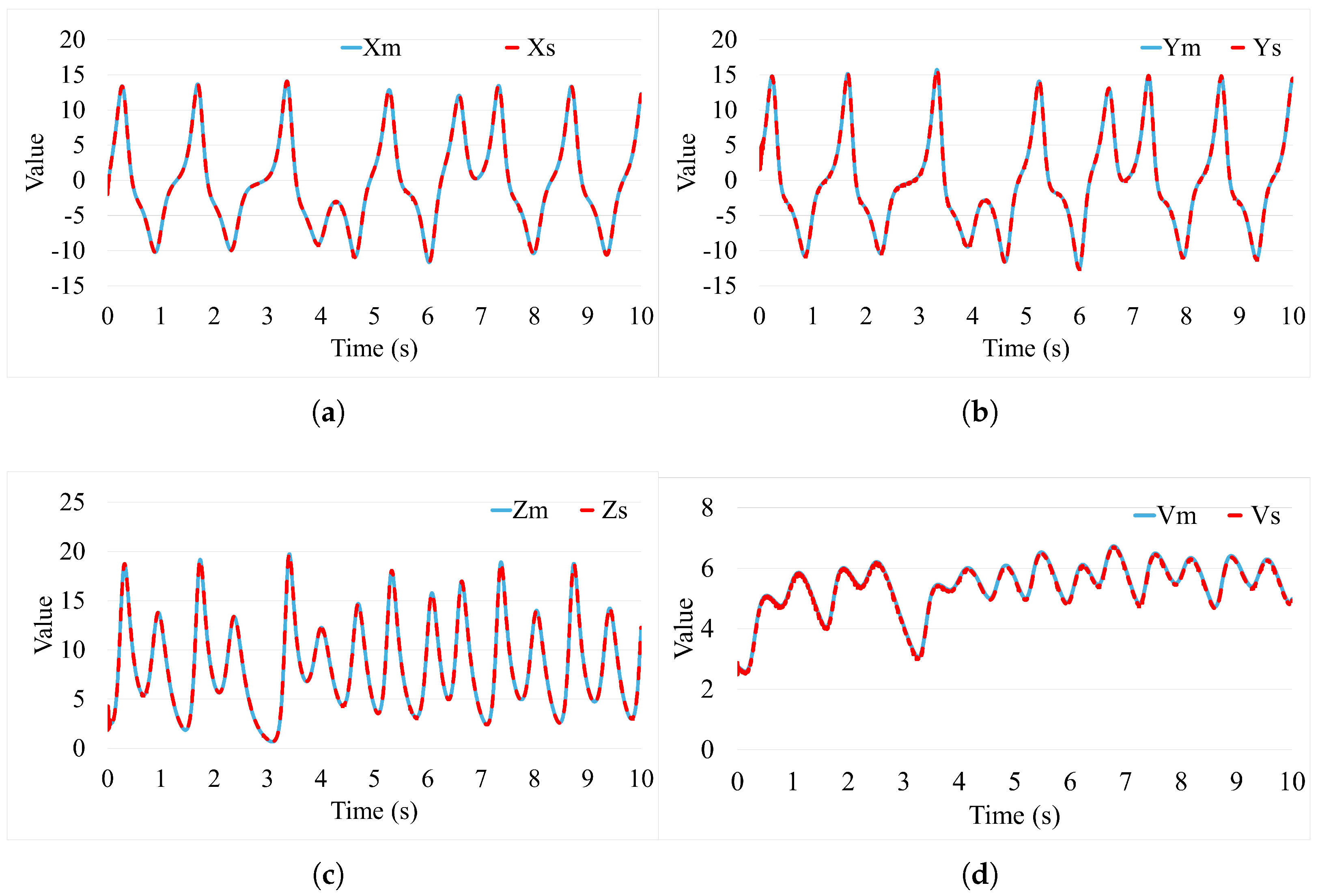
A simulation study was carried out by using MATLAB 2023a on a computer with CPU Intel(R) Core(TM) i512400F, RAM 32 GB. The parameters of the controller are as follows: K 1 = k 11 0 0 k 12 , k 11 = 1.6 , k 12 = 0.02 , α = 0.01 , β = 0.01 , σ ij = 3 . These parameters were chosen based on the stable conditions (9) and (15). ξ ij = [ 2 , 1.6 , 1.2 , 0.8 , 0 , 0.4 , 0.8 , 1.2 , 1.6 , 2 ] were chosen for R = 0.06 (12) and (14) and R = 0.06 . Figure 3 shows the state of the master and slave systems on each axis.
As shown in Figure 4, the synchronization error, initially present due to differing starting points, quickly diminishes to near zero under control action, indicating rapid synchronization (within about 10 ms). The sustained near-zero error confirms the pro-posed controller’s stability. Steady-state tracking exhibits extremely small errors (around 10 5 ). When a disturbance was introduced, the error briefly rose significantly to 8 × 10 3 but swiftly recovered to the stable, minimal level. This demonstrates the controller’s efficiency in providing both fast and robust synchronization.
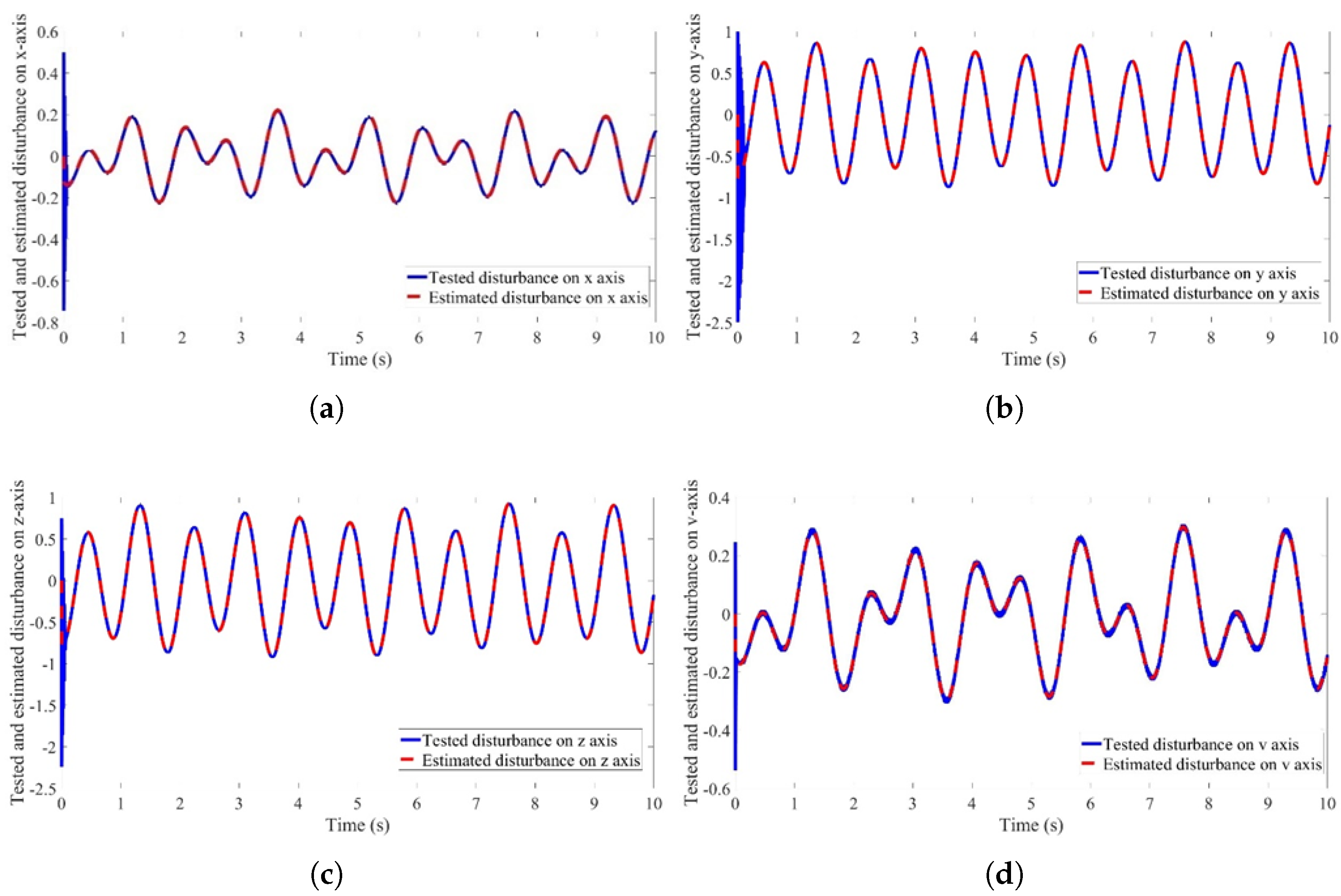
All four axes of the chaotic system will have a signal added as a tested disturbance; the signal added to x axis is 0.125 × cos ( 2.5 π × ( ) × h ) + 0.1 × sin ( 1.5 × π × ( ) × h ) ; the signal added to y axis is 0.75 × cos ( 2.25 π × ( ) × h ) + 0.125 × sin ( 1.25 × π × ( ) × h ) ; the signal added to z axis is 0.75 × cos ( 2.25 π × ( ) × h ) + 0.175 × sin ( 1.25 × π × ( ) × h ) and the signal added to v axis is 0.15 × cos ( 2.25 π × ( ) × h ) + 0.15 × sin ( 1.25 × π × ( ) × h ) . Figure 5 illustrates the efficacy of the DO in the estimation and compensation of external disturbances affecting the system. The observer’s successful tracking of disturbance dynamics ensures system stability in the presence of external perturbations. The close agreement between the tested and estimated disturbance confirms the proposed observer’s capacity for real-time disturbance rejection. These results validate the DO’s robustness in mitigating external uncertainties, a critical factor for maintaining synchronization accuracy.

3.2. Experiment Study

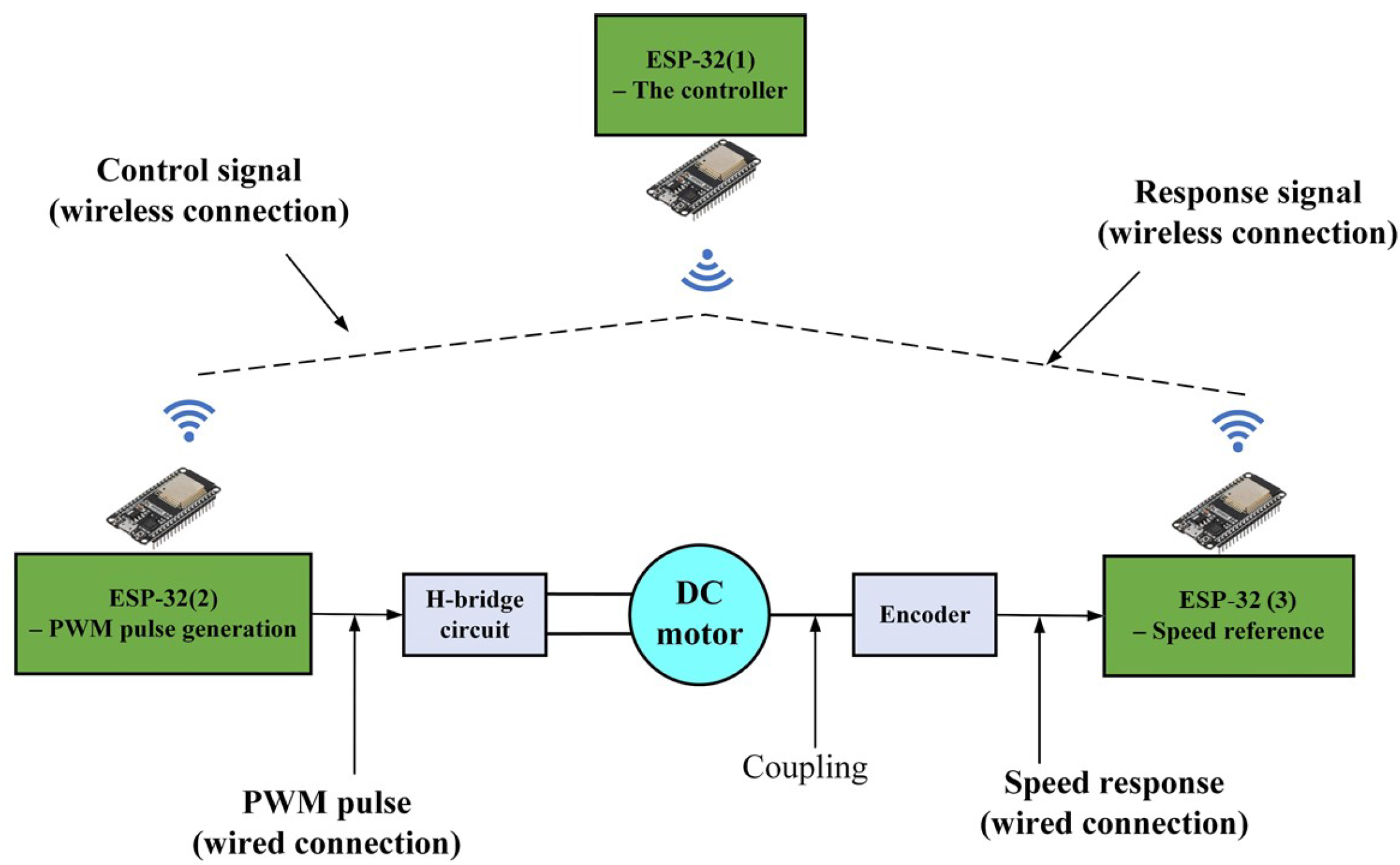
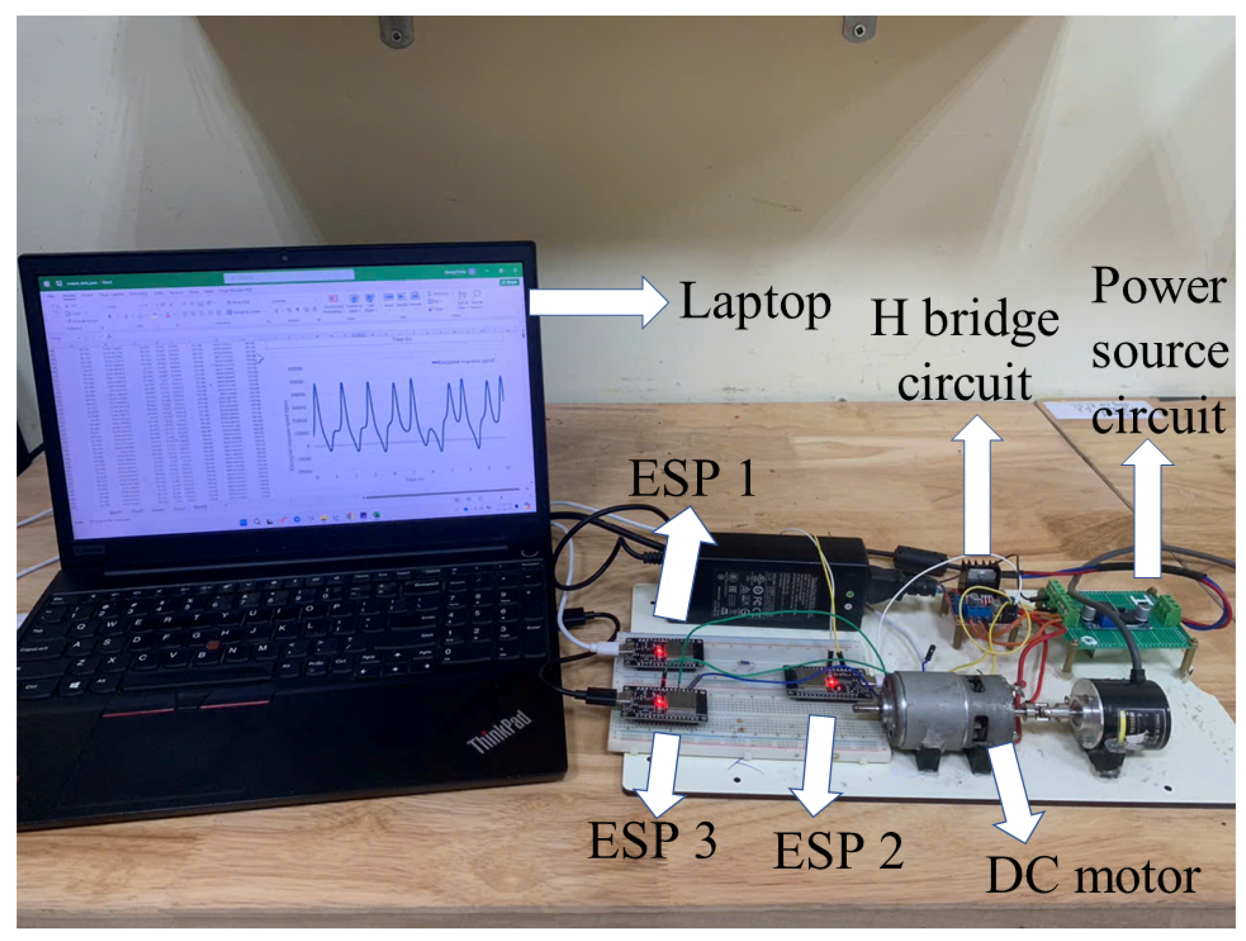
A scenario was carried out using the wireless communication protocol as in Figure 6 and Figure 7. Herein, three ESP32 chips are used to control a DC motor wirelessly. ESP32(1) plays the controller role, sending the control signal to ESP32(2). ESP32(2) uses the data sent from ESP32(1) to create the corresponding PWM pulse to control the DC motor. ESP32(3) takes the speed of the motor and sends it to ESP32(1) to calculate the control data based on the PI controller. Each of the two chips communicates with the other via the ESP-NOW protocol. The computer also provides the power source for three wireless devices. Both the electrical driver control signal and the response speed will be encrypted by using the chaotic system. They will be added into one of three system states of the master system and then this mixed information is sent to the slave via wireless communication. The state of the slave will be used to encrypt data it gets from the master.
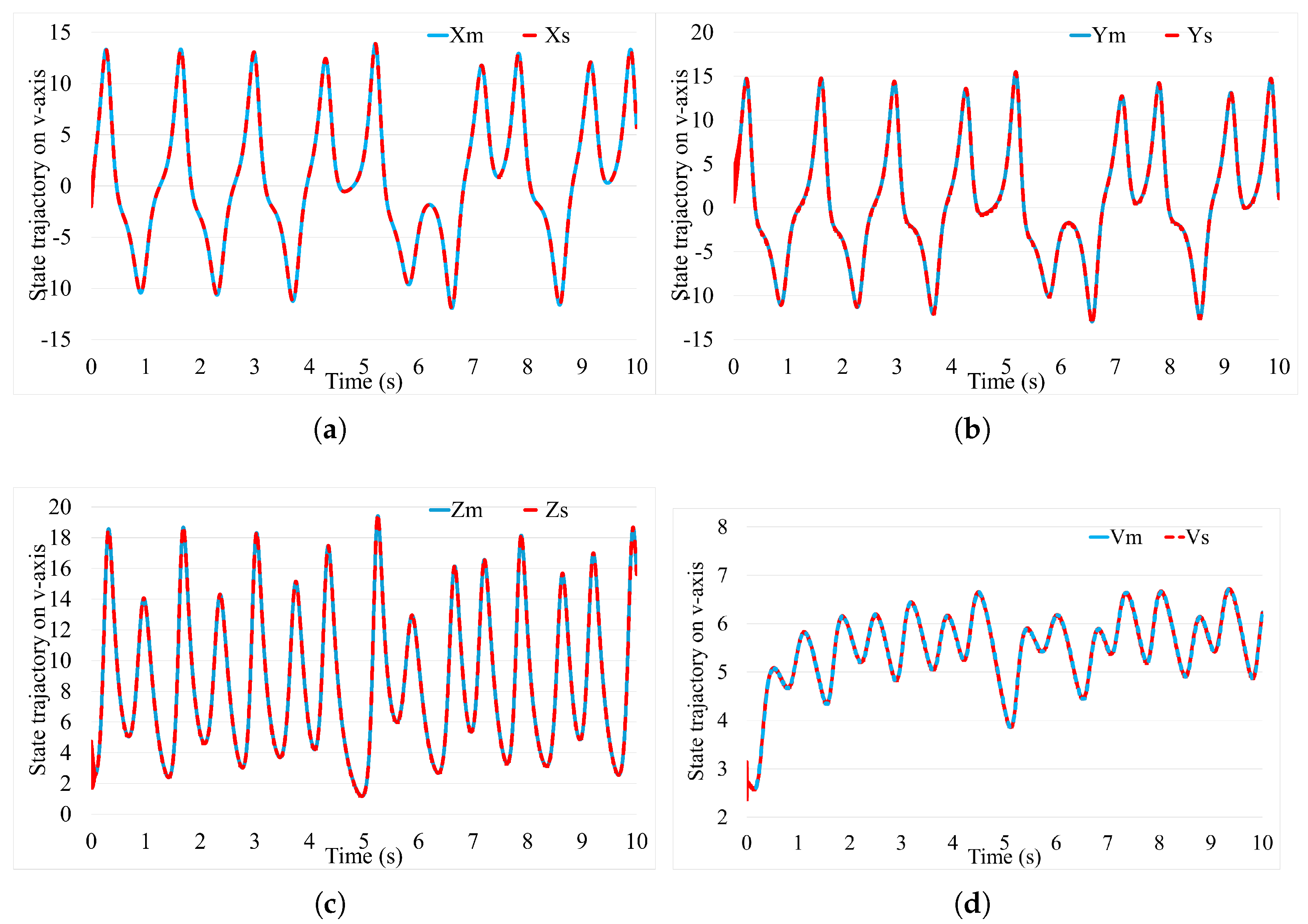
The parameters of the controller are as follows: K 1 = k 11 0 0 k 12 , k 11 = 1.6 , k 12 = 0.02 , α = 0.01 , β = 0.01 , σ ij = 3 . These parameters are chosen based on the stable conditions (9) and (15). ξ ij = [ 2 , 1.6 , 1.2 , 0.8 , 0 , 0.4 , 0.8 , 1.2 , 1.6 , 2 ] are chosen for R = 0.06 (12) and (14) and R = 0.06 . Figure 8 ensures the reliability of the SCS by describing the accuracy of the proposed control method. It shows the state trajectory of two systems on each axis x , y , z and v, respectively.
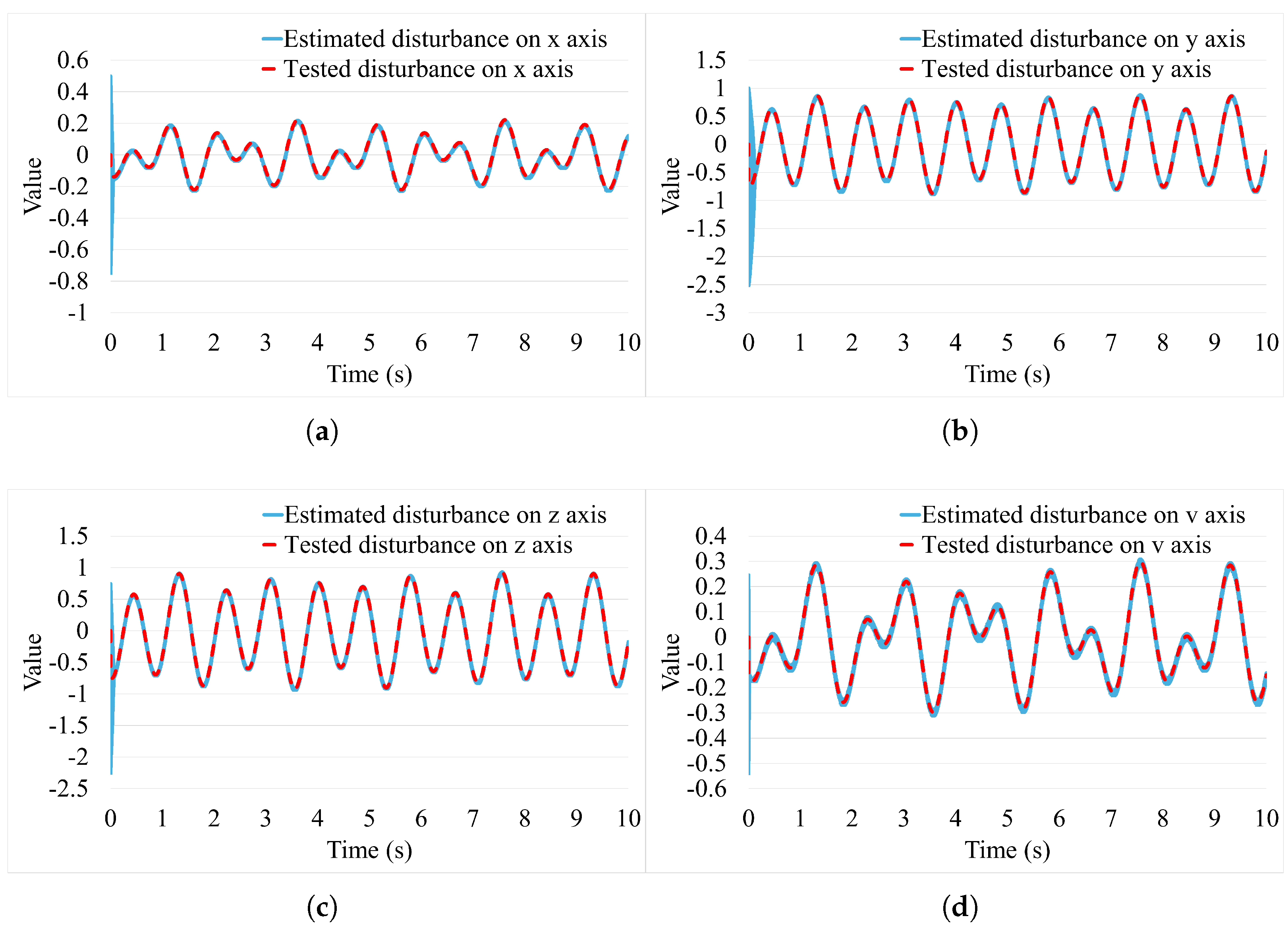
All four axes of the chaotic system will be added a signal to each as a tested disturbance; the signal added to x axis is 0.125 × cos ( 2.5 π × ( ) × h ) + 0.1 × sin ( 1.5 × π × ( ) × h ) ; the signal added to y axis is 0.75 × cos ( 2.25 π × ( ) × h ) + 0.125 × sin ( 1.25 × π × ( ) × h ) ; the signal added to z axis is 0.75 × cos ( 2.25 π × ( ) × h ) + 0.175 × sin ( 1.25 × π × ( ) × h ) and the signal added to v axis is 0.15 × cos ( 2.25 π × ( ) × h ) + 0.15 × sin ( 1.25 × π × ( ) × h ) . Figure 9 effectively demonstrates the DO’s capability in both estimating and compensating for external disturbances affecting the system. The observer adeptly tracks the dynamics of these disturbances, which in turn ensures the system’s stability even in the presence of external perturbations. The close agreement between the tested and estimated disturbance values provides strong confirmation of the proposed observer’s proficiency in real-time disturbance rejection. Ultimately, these results validate the DO’s robustness in mitigating external uncertainties, a critical factor for maintaining high synchronization accuracy.
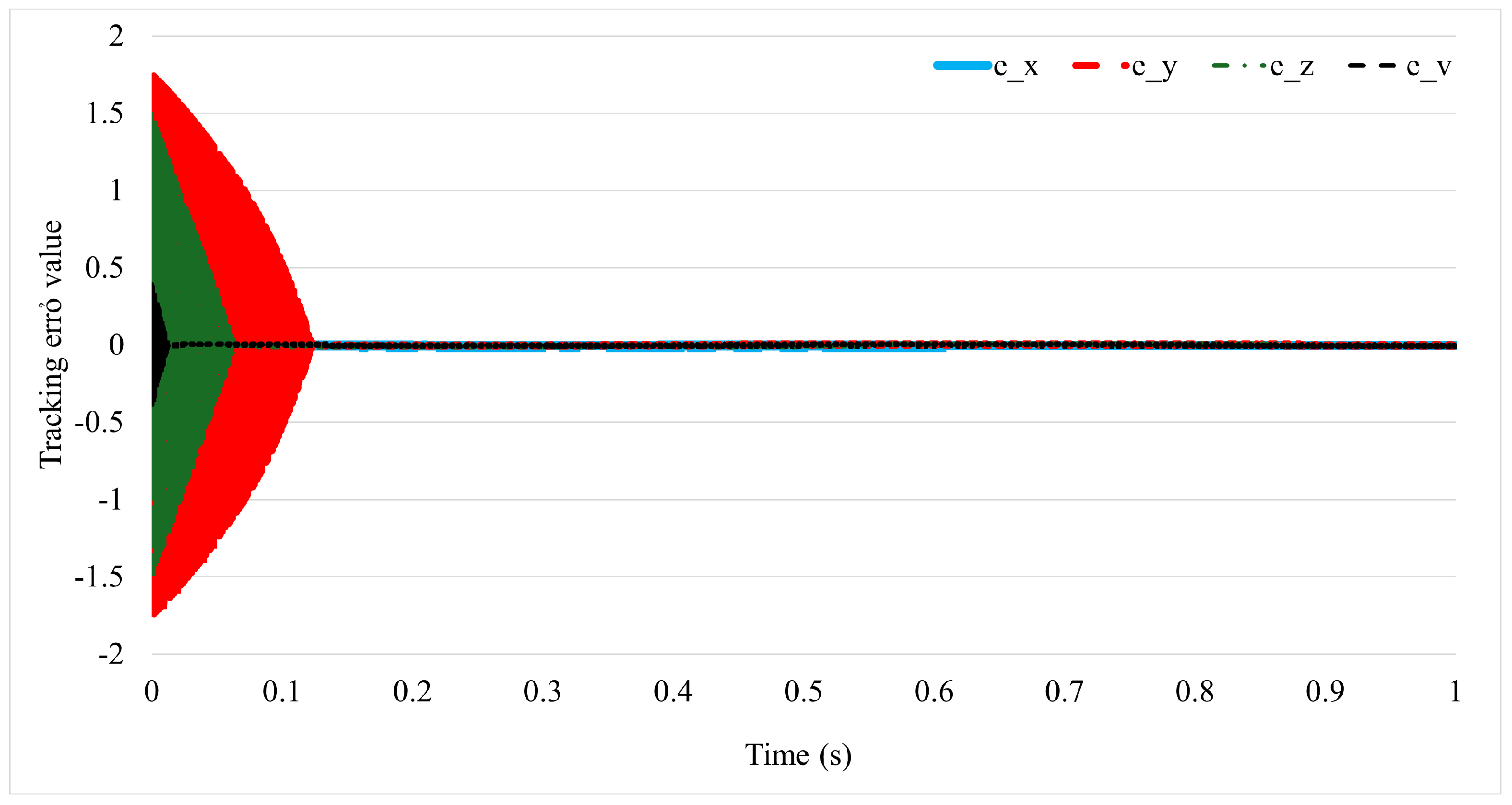
This depicts the tested disturbances applied to the system and the corresponding estimates produced by the disturbance observer. The close alignment of the tested and estimated values across all axes ( x , y , z , and v) demonstrates the effectiveness of the disturbance observer in identifying and compensating for external perturbations. The evolution of the tracking error through time is shown in Figure 10. Initially, the error is nonzero due to the difference in initial conditions between the master and slave systems. However, as the controller takes effect, the error rapidly decreases to zero, demonstrating the system’s ability to quickly synchronize.
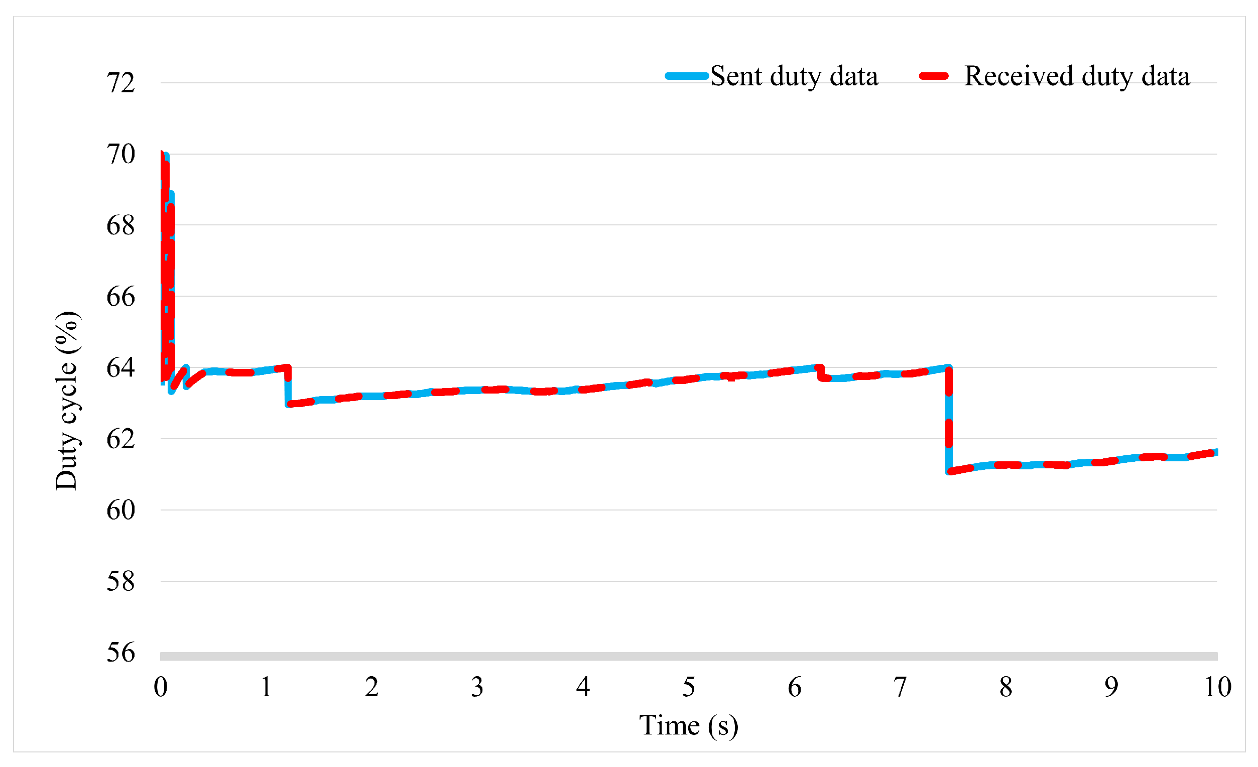
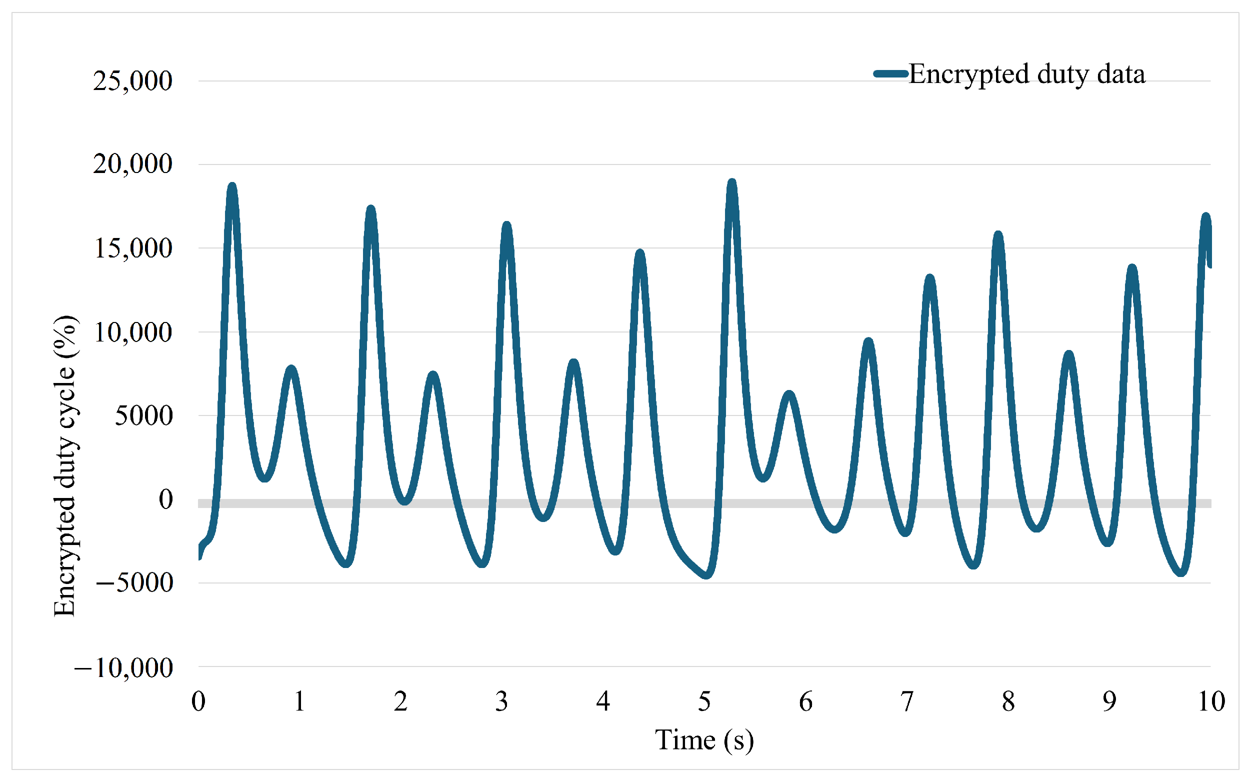
Figure 11 illustrates the original and decrypted data, and Figure 12 shows the encrypted control data. The encrypted control signal appears highly randomized, ensuring that meaningful information cannot be extracted by unauthorized entities and the decrypted signal closely matches the original, verifying the accuracy and reliability of the proposed communication method.
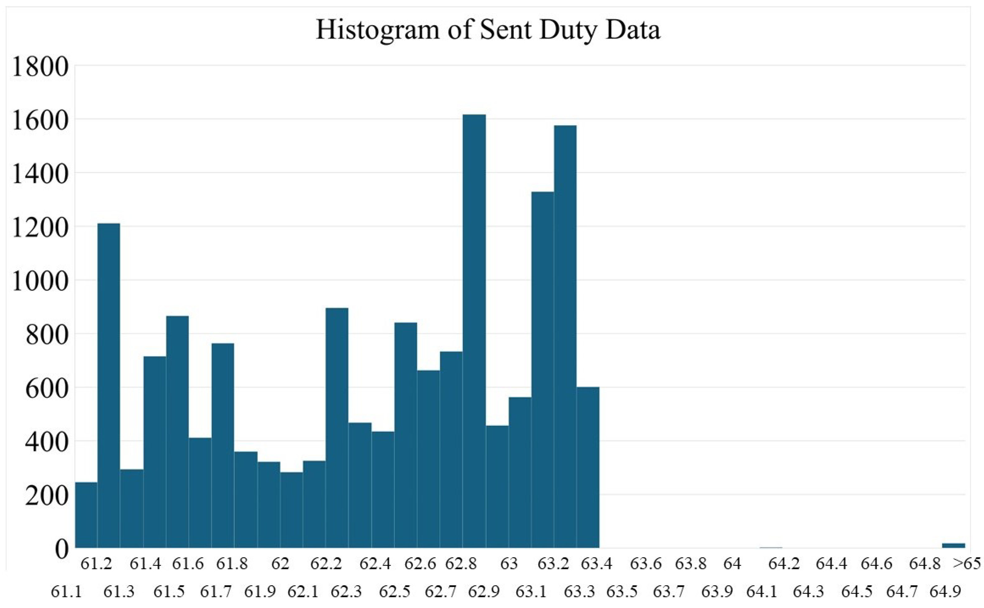
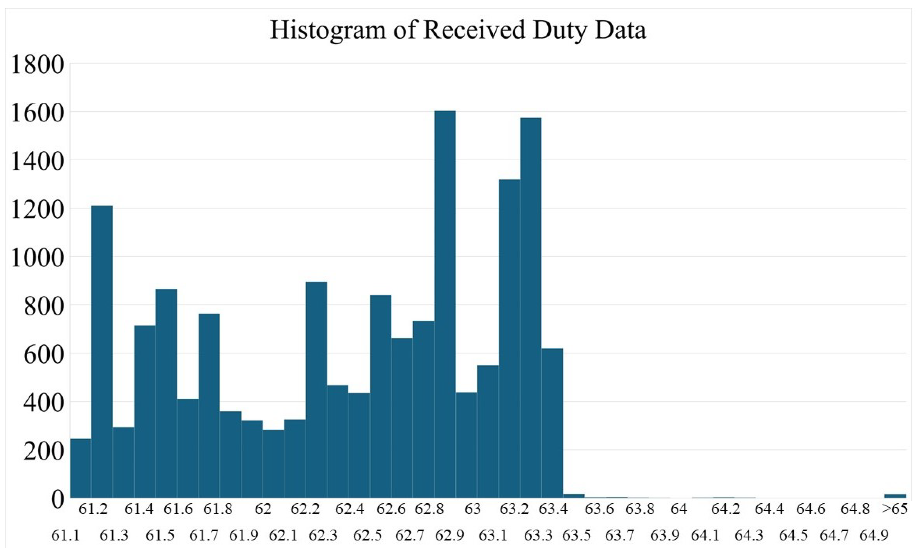
Figure 13, Figure 14 and Figure 15 confirms that the encryption scheme effectively obscures the transmitted data by showing the histogram chart of all three scenarios: encrypted, decrypted, and original control signal. This ensures a good performance of the proposed system. However, minor discrepancies between the original and decrypted signals may be attributed to numerical discretization or slight residual errors from the synchronization process.
The effectiveness of the system will be evaluated by using two indexes: the average error in differences between original signal and the decrypted signal and the average difference in gradients between the original signal and the decrypted signal. The average error in differences between the original signal and the decrypted signal is calculated as follows:
e r r _ a v g = M M ^ t 2 t 1
The average difference in gradients between the original signal and the decrypted signal is calculated as follows:
d i f f _ a v g = 1 t 2 t 1 ( d A [ n ] d B [ n ] )
Herein, d A [ n ] is the gradient of the original data M, and d B [ n ] is the gradient of the decrypted data. The averages of these mentioned signals are located in the gaps of 1 t 1 < t 2 < n , where n is an element of d A and d B . The average differences of absolute elements of sent and received data are checked by the exhaustive attacks. Using Equations (56) and (57), the average difference in gradients is 0.4164 × 10 5 , and the average difference between sent and received data is 0. Additionally, to assess the randomness and cryptographic strength of the chaos-based encryption mechanism, the Shannon entropy of the encrypted control signal was computed. The entropy H is calculated as:
H = i = 1 n p i log 2 p i
where p i is the probability of the occurrence of symbol i in the encrypted data. The analysis was performed on the binary representation of encrypted control signals over 8-bit segments. The resulting entropy was measured to be approximately 7.298238654 bits per byte, which is close to the ideal value of 8 for truly random data. This indicates a high degree of uncertainty and supports the effectiveness of the proposed chaotic encryption scheme in resisting statistical attacks. Shannon entropy analysis confirms that the encrypted data exhibits high randomness ( 7.98 / 8 ) , indicating strong resistance to statistical attacks and validating the cryptographic reliability of the proposed chaos-based secure control scheme.
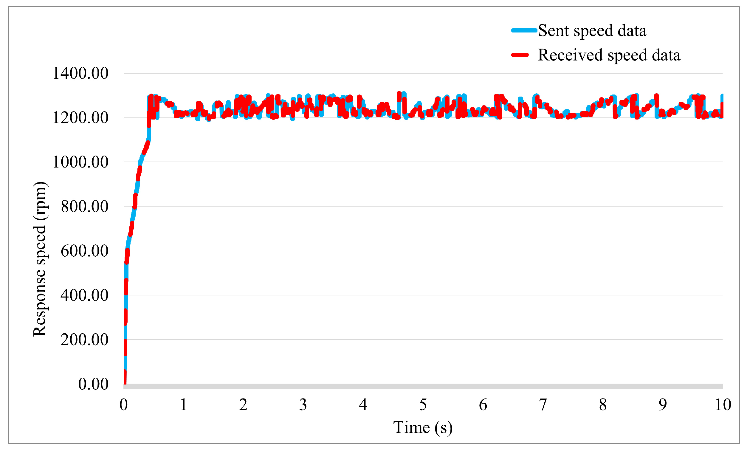
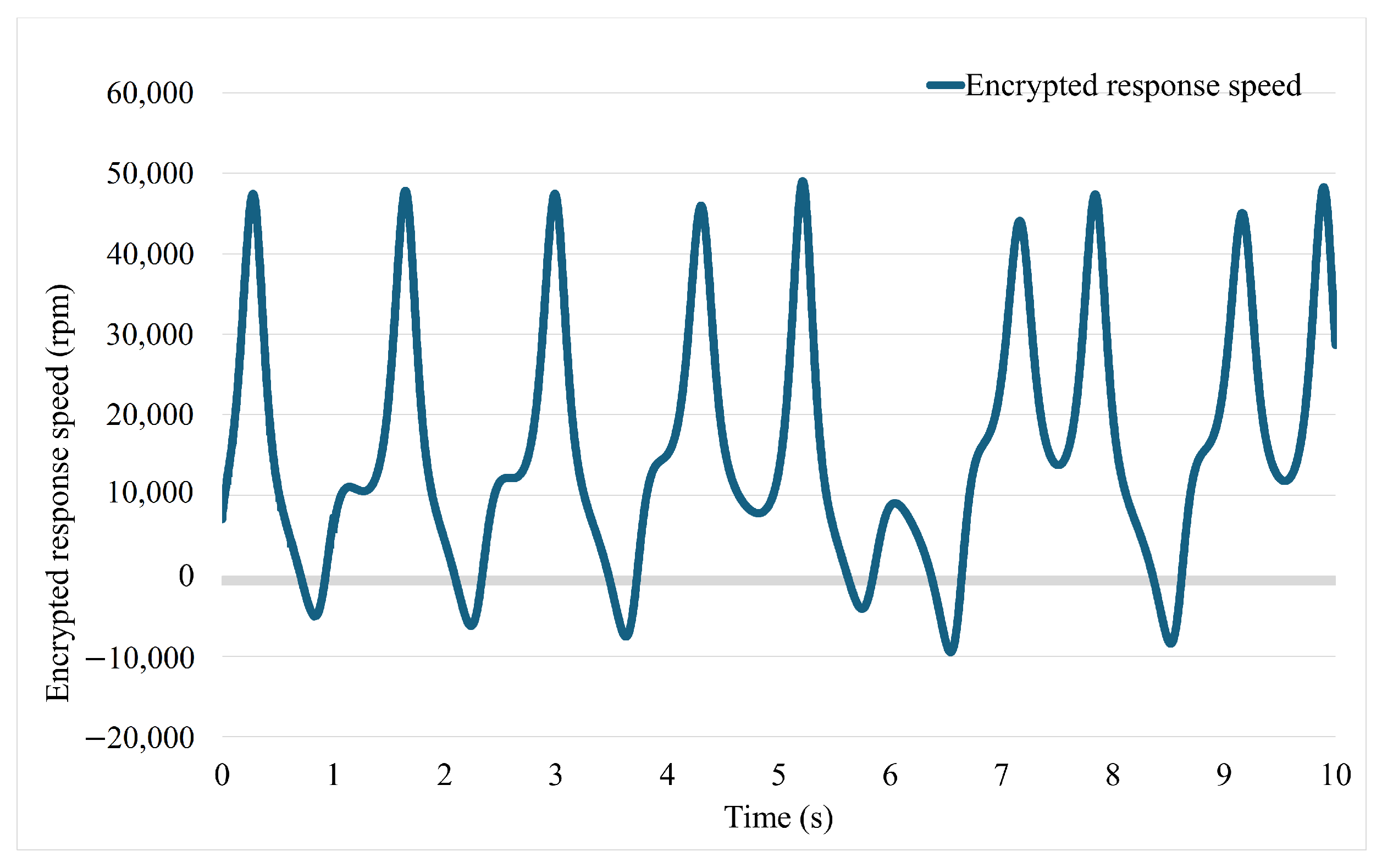
Herein, the response speed signal is encrypted and sent from ESP32(2) to ESP32(3) via an ESP-NOW protocol. Figure 16 and Figure 17 illustrate the original, decrypted and encrypted response speed signal.
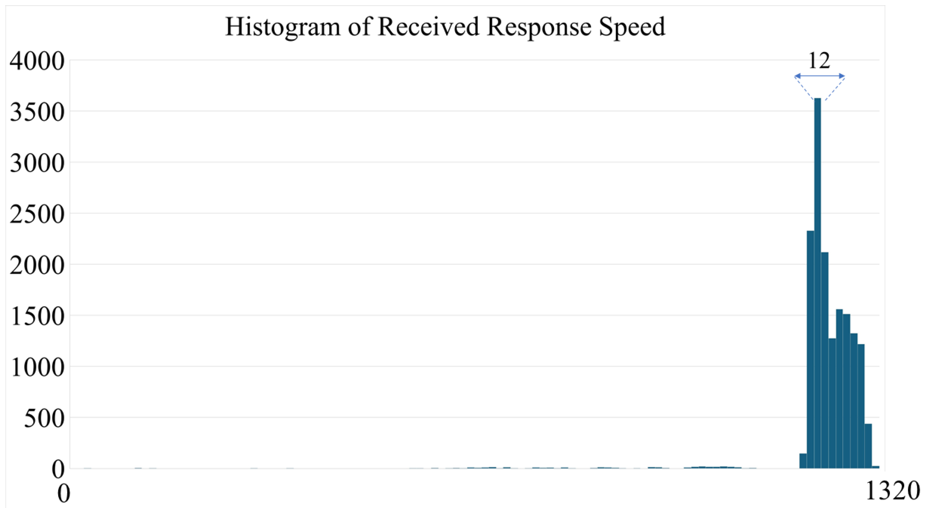
Figure 18, Figure 19 and Figure 20 present a statistical analysis of the secure communication process through histograms of the original, encrypted, and decrypted response speed signals.
The histogram of the encrypted signal demonstrates a nearly uniform distribution, indicating that the encryption method successfully removes recognizable patterns, making the transmitted data highly resistant to decryption attempts. Meanwhile, the decrypted signal’s histogram closely resembles that of the original signal, confirming that the proposed system preserves data integrity. Using Equations (56), (57) and (58), the average difference in gradients is 1.2944 ×   10 5 . The average difference between sent and received data is 0. The resulting entropy was measured to be approximately 7.348238654 bits per byte.

3.3. PI Controller

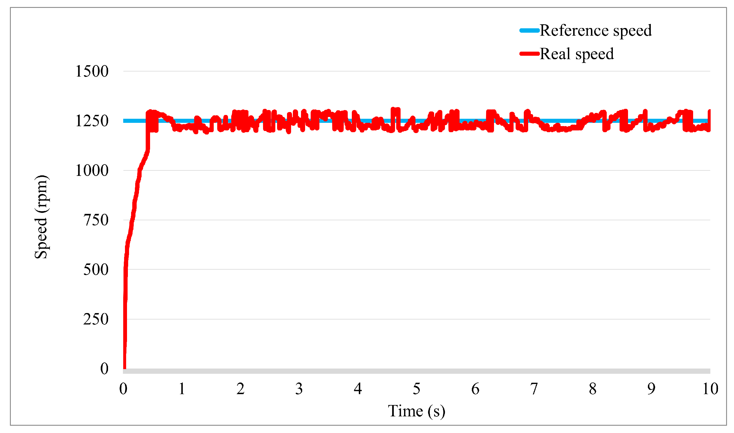
Figure 21 illustrates the effectiveness of the PI controller in regulating the motor’s dynamics, ensuring stable and accurate control of speed. The trajectory of the motor’s response shows that the PI controller achieves a relatively fast and smooth convergence to the desired reference value. This confirms its capability to regulate the motor under normal operating conditions.

4. Conclusions

This paper presented a novel and secure control architecture for smart electric drive systems, leveraging ESP-NOW wireless communication and an integrated fuzzy brain emotional learning neural network (FBELNN) controller combined with the DO. The proposed approach addresses the increasing need for robust and secure real-time control in cyber-physical systems, particularly under external disturbances and uncertainties. Compared to conventional PID-based or fixed-structure adaptive controllers, the FBELNN offers significant improvements in adaptability and learning capability, enabling superior disturbance rejection and dynamic tracking performance. The incorporation of DOB further enhances system robustness by actively compensating for unknown disturbances. In contrast to existing wireless control systems that are often vulnerable to cyber-attacks or suffer from communication latency, our framework utilizes lightweight, real-time ESP-NOW communication and chaotic encryption to ensure secure, low-latency data transmission. Experimental validation on a DC motor tested demonstrated clear advantages over traditional control methods in terms of response time, tracking accuracy, and disturbance resilience, all within a compact and low-cost hardware setup based on ESP32 microcontrollers. Notably, the bidirectional communication among distributed nodes enables decentralized control, which is rarely addressed in comparable low-power embedded systems.

Limitations of the Study

Despite these promising outcomes, the current prototype is limited to small-scale applications and does not yet integrate industrial-grade protocols or hardware. Additionally, compliance with cybernetics standards such as IEC 62443 and industrial drive protocols like IEC 61800 remains to be addressed. Future work will aim to scale the system for deployment in larger, high-speed industrial environments and enhance conformity with recognized standards to enable broader applicability in smart manufacturing and Industry 4.0 contexts.

Author Contributions

Conceptualization, H.C.P.T. and V.N.G.; methodology, V.N.G.; software, N.Q.D.; validation, H.C.P.T. and V.N.G.; formal analysis, V.N.G.; investigation, N.Q.D.; resources, H.C.P.T.; data curation, H.C.P.T.; writing—original draft, H.C.P.T.; writing—review and editing, H.C.P.T.; visualization, H.C.P.T.; supervision, V.N.G. All authors have read and agreed to the published version of the manuscript.

Funding

This research is funded by Hanoi University of Science and Technology (HUST) under project number T2024-PC-049.

Data Availability Statement

Dataset available on request from the authors.

Conflicts of Interest

The authors declare no conflicts of interest.

References

  1. Yan, J.J.; Shyu, K.K.; Lin, J.S. Adaptive variable-structure control for uncertain chaotic systems containing dead-zone non-linearity. Chaos Solit. Fractals 2005, 25, 347–355. [Google Scholar] [CrossRef]
  2. Lin, C.-M.; Mon, Y.-J. Decoupling control by hierarchical fuzzy sliding-mode controller. IEEE Trans. Control. Syst. Technol. 2005, 13, 593–598. [Google Scholar] [CrossRef]
  3. Giap, V.N.; Nguyen, Q.D.; Pham, D.H.; Lin, C.M. Wireless secure communication of chaotic systems based on Takagi–Sugeno fuzzy optimal time-varying Disturbance Observer and sliding-mode control. Int. J. Fuzzy Syst. 2023, 25, 2519–2533. [Google Scholar] [CrossRef]
  4. Giap, V.N. Text message secure communication based on fractional-order chaotic systems with Takagi–Sugeno fuzzy Disturbance Observer and sliding-mode control. Int. J. Dyn. Control. 2023, 11, 3109–3123. [Google Scholar] [CrossRef]
  5. Giap, V.-N.; Huang, S.-C.; Nguyen, Q.D. Synchronization of 3D Chaotic System Based on Sliding Mode Control: Electronic Circuit Implementation. In Proceedings of the 2020 IEEE Eurasia Conference on IOT, Communication and Engineering (ECICE), Yunlin, Taiwan, 23–25 October 2020; pp. 156–159. [Google Scholar] [CrossRef]
  6. Lin, C.M.; Ting, A.B.; Hsu, C.F.; Chung, C.M. Adaptive control for MIMO uncertain nonlinear systems using recurrent wavelet neural network. Int. J. Neural Syst. 2012, 22, 37–50. [Google Scholar] [CrossRef]
  7. AL-Hussein, A.B.A. Neural Network-Based Adaptive Control of Robotic Manipulator: Application to a Three Links Cylindrical Robot. Iraqi J. Electr. Electron. Eng. 2017, 13, 114–122. [Google Scholar] [CrossRef]
  8. Pham, D.-H.; Lin, C.-M.; Giap, V.N.; Huynh, T.-T.; Cho, H.-Y. Wavelet Interval Type-2 Takagi-Kang-Sugeno Hybrid Controller for Time-Series Prediction and Chaotic Synchronization. IEEE Access 2022, 10, 104313–104327. [Google Scholar] [CrossRef]
  9. Chen, C.L.P.; Liu, Y.-J.; Wen, G.-X. Fuzzy Neural Network-Based Adaptive Control for a Class of Uncertain Nonlinear Stochastic Systems. IEEE Trans. Cybern. 2014, 44, 583–593. [Google Scholar] [CrossRef]
  10. Chen, C.-S. Robust Self-Organizing Neural-Fuzzy Control With Uncertainty Observer for MIMO Nonlinear Systems. IEEE Trans. Fuzzy Syst. 2011, 19, 694–706. [Google Scholar] [CrossRef]
  11. Fang, W.; Chao, F.; Lin, C.M.; Yang, L.; Shang, C.; Zhou, C. An Improved Fuzzy Brain Emotional Learning Model Network Controller for Humanoid Robots. Front. Neurorobotics 2019, 13, 2. [Google Scholar] [CrossRef]
  12. Jin, J.; Fang, J.; Chen, C.; Li, Z.; Yu, F. A complex-valued time varying zeroing neural network model for synchronization of complex chaotic systems. Nonlinear Dyn. 2024, 113, 5471–5491. [Google Scholar] [CrossRef]
  13. Yu, F.; He, S.; Yao, W.; Cai, S.; Xu, Q. Bursting Firings in Memristive Hopffeld Neural Network with Image Encryption and Hardware Implementation. IEEE Trans.-Comput.-Aided Des. Integr. Circuits Syst. 2025; early access. [Google Scholar] [CrossRef]
  14. Marr, D. A theory of cerebellar cortex. J. Physiol. 1969, 202, 437–470. [Google Scholar] [CrossRef]
  15. Albus, J.S. A new approach to manipulator control: The cerebellar model articulation controller (CMAC). J. Dyn. Syst. Meas. Control 1975, 97, 220–227. [Google Scholar] [CrossRef]
  16. Cheng, K.-H. Adaptive fuzzy CMAC-based nonlinear control with dynamic memory architecture. J. Frankl. Inst. 2011, 348, 2480–2502. [Google Scholar] [CrossRef]
  17. Chiu, C.-H. Adaptive output recurrent cerebellar model articulation controller for nonlinear system control. Soft Comput. 2010, 14, 627–638. [Google Scholar] [CrossRef]
  18. Lin, C.M.; Huynh, T.T.; Le, T.L. Adaptive TOPSIS fuzzy CMAC back-stepping control system design for nonlinear systems. Soft Comput. 2019, 23, 6947–6966. [Google Scholar] [CrossRef]
  19. Lin, C.M.; Li, H.Y. TSK Fuzzy CMAC-Based Robust Adaptive Backstepping Control for Uncertain Nonlinear Systems. IEEE Trans. Fuzzy Syst. 2012, 20, 1147–1154. [Google Scholar] [CrossRef]
  20. Ortiz, F.; Yu, W.; Moreno-Armendariz, M.; Li, X. Recurrent Fuzzy CMAC for Nonlinear System Modeling. In Advances in Neural Networks; Lecture Notes in Computer Science; Springer: Berlin/Heidelberg, Germany, 2007; Volume 4491. [Google Scholar] [CrossRef]
  21. Lin, C.M.; Li, H.Y. Dynamic Petri Fuzzy Cerebellar Model Articulation Controller Design for a Magnetic Levitation System and a Two-Axis Linear Piezoelectric Ceramic Motor Drive System. IEEE Trans. Control. Syst. Technol. 2015, 23, 693–699. [Google Scholar] [CrossRef]
  22. LeDoux, J.E. Emotion and the amygdala: Fear, anxiety, and aggression. In The Amygdala: Neurobiological Aspects of Emotion, Memory, and Mental Dysfunction; Wiley-Liss: Hoboken, NJ, USA, 1992; pp. 339–351. [Google Scholar]
  23. Balkenius, C.; Moren, J. Emotional learning: A computational model of the amygdala. Cybern. Syst. 2001, 32, 611–636. [Google Scholar] [CrossRef]
  24. Pham, D.H.; Lin, C.M.; Giap, V.N. Intelligent control-system design for nonlinear systems using an improved TSK wavelet type-2 fuzzy brain-emotional controller. Int. J. Fuzzy Syst. 2024, 26, 2632–2645. [Google Scholar] [CrossRef]
  25. Moren, J.; Balkenius, C. A computational model of emotional learning in the amygdala. In From Animals to Animats 7; MIT Press: Cambridge, MA, USA, 2002; pp. 115–124. [Google Scholar]
  26. Lucas, C.; Salari, K.; Sheikholeslami, N. Introducing BELBIC: Brain emotional learning-based intelligent controller. Int. J. Intell. Autom. Soft Comput. 2004, 10, 11–22. [Google Scholar] [CrossRef]
  27. Rouhani, H.; Jalili, M.; Araabi, B.N.; Eppler, W.; Lucas, C. Brain emotional learning based intelligent controller applied to neurofuzzy model of micro-heat exchanger. Expert Syst. Appl. 2007, 32, 911–918. [Google Scholar] [CrossRef]
  28. Samimi, M.; Majidi, M.H.; Khorashadizadeh, S. Secure communication based on chaos synchronization using brain emotional learning. AEU—Int. J. Electron. Commun. 2020, 127, 153424. [Google Scholar] [CrossRef]
  29. Le, M.C.; Giap, V.N.; Nguyen, Q.D.; Huang, S.-C. Electrocardiogram Signal Secure Transmission via a Wireless Communication Protocol of Chaotic Systems Based on Adaptive Sliding Mode Control and Disturbance Observer. IEEE Access 2023, 11, 145373–145385. [Google Scholar] [CrossRef]
  30. Min, F.; Chen, C.; Broderick, N.G. Coupled Homogeneous Hopfield Neural Networks: Simplest Model Design, Synchronization, and Multiplierless Circuit Implementation. IEEE Trans. Neural Netw. Learn. Systems. 2025, 36, 11632–11639. [Google Scholar] [CrossRef]
  31. Deng, Q.; Wang, C.; Yang, G.; Luo, D. Discrete Memristive Delay Feedback Rulkov Neuron Model: Chaotic Dynamics, Hardware Implementation, and Application in Secure Communication. IEEE Internet Things J. 2025, 12, 25559–25567. [Google Scholar] [CrossRef]
  32. Lin, C.-M.; Pham, D.-H.; Huynh, T.-T. Encryption and Decryption of Audio Signal and Image Secure Communications Using Chaotic System Synchronization Control by TSK Fuzzy Brain Emotional Learning Controllers. IEEE Trans. Cybern. 2022, 52, 13684–13698. [Google Scholar] [CrossRef]
  33. Giap, V.N.; Vu, H.S.; Nguyen, Q.D.; Huang, S.C. Disturbance-and-uncertainty rejection based on fixed-time sliding-mode control for the secure communication of chaotic systems. IEEE Access 2021, 9, 133663–133685. [Google Scholar] [CrossRef]
  34. Nguyen, Q.D.; Huang, S.C.; Giap, V.N. Lyapunov-based fractional-order Disturbance Observer and sliding-mode control for a secure communication of chaos-based system. Int. J. Control Autom. Syst. 2023, 21, 3595–3606. [Google Scholar] [CrossRef]
  35. Nguyen, Q.D.; Vu, D.D.; Huang, S.-C.; Giap, V.N. Fixed-time supper twisting Disturbance Observer and sliding mode control for a secure communication of fractional-order chaotic systems. J. Vib. Control. 2023, 30, 2568–2581. [Google Scholar] [CrossRef]
  36. Zhu, S.; Deng, X.; Zhang, W.; Zhu, C. Secure image encryption scheme based on a new robust chaotic map and strong S-box. Math. Comput. Simul. 2023, 207, 322–346. [Google Scholar] [CrossRef]
  37. Pallav; Handa, H. Chaos synchronization for a class of hyper-chaotic systems using active SMC and PI SMC: A comparative analysis. J. Control Autom. Electr. Syst. 2022, 33, 1671–1687. [Google Scholar] [CrossRef]
  38. Lyu, B.; Liu, C.; Yue, X. Integrated Predictor–Observer Feedback Control for Vibration Mitigation of Large-Scale Spacecraft With Unbounded Input Time Delay. IEEE Trans. Aerosp. Electron. Syst. 2025, 61, 4561–4572. [Google Scholar] [CrossRef]
  39. Liu, C.; Yue, X.; Zhang, J.; Shi, K. Active Disturbance Rejection Control for Delayed Electromagnetic Docking of Spacecraft in Elliptical Orbits. IEEE Trans. Aerosp. Electron. Syst. 2022, 58, 2257–2268. [Google Scholar] [CrossRef]
  40. Lyu, B.; Liu, C.; Yue, X. Hybrid nonfragile intermediate observer-based T-S fuzzy attitude control for flexible spacecraft with input saturation. Aerosp. Sci. Technol. 2022, 128, 107753. [Google Scholar] [CrossRef]
  41. Hadji, M.M.; Ladaci, S. A novel secure-communication-scheme design using a fractional-order adaptive observer-based synchronization. J. Control Autom. Electr. Syst. 2025, 36, 267–282. [Google Scholar] [CrossRef]
  42. Yu, F.; Zhang, S.; Su, D.; Wu, Y.; Gracia, Y.M.; Yin, H. Dynamic Analysis and Implementation of FPGA for a New 4D Fractional-Order Memristive Hopfield Neural Network. Fractal Fract. 2025, 9, 115. [Google Scholar] [CrossRef]
  43. Deng, Q.; Wang, C.; Sun, Y.; Yang, G. Discrete Memristive Conservative Chaotic Map: Dynamics, Hardware Implementation, and Application in Secure Communication. IEEE Trans. Cybern. 2025; early access. [Google Scholar] [CrossRef]
  44. Wan, Q.; Yang, Q.; Liu, T.; Chen, C.; Shen, K. Single direction, grid and spatial multi-scroll attractors in Hopfield neural network with the variable number memristive self-connected synapses. Chaos Solit. Fractals 2024, 189, 115584. [Google Scholar] [CrossRef]
  45. Ortigueira, M.D.; Machado, J.A.T. New discrete-time fractional derivatives based on the bilinear transformation: Definitions and properties. J. Adv. Res. 2020, 25, 1–10. [Google Scholar] [CrossRef] [PubMed]
  46. Lin, C.M.; Chung, C.C. Fuzzy Brain Emotional Learning Control System Design for Nonlinear Systems. Int. J. Fuzzy Syst. 2015, 17, 117–128. [Google Scholar] [CrossRef]
Figure 1. Lyapunov exponents of chaotic system.
Mca 30 00073 g001
Figure 2. Structure of fuzzy brain emotional learning.
Mca 30 00073 g002
Figure 3. State trajectory on (a) x-axis (b) y-axis (c) z-axis and (d) v-axis.
Mca 30 00073 g003
Figure 4. Tracking error of the system through time.
Mca 30 00073 g004
Figure 5. Tested and estimated disturbance on (a) x-axis, (b) y-axis, (c) z-axis, and (d) v-axis.
Mca 30 00073 g005
Figure 6. Structure of the experimental system.
Mca 30 00073 g006
Figure 7. Experimental setup.
Mca 30 00073 g007
Figure 8. State trajectory on (a) x-axis, (b) y-axis, (c) z-axis, and (d) v-axis.
Mca 30 00073 g008
Figure 9. Tested and estimated disturbance on (a) x-axis, (b) y-axis, (c) z-axis, and (d) v-axis.
Mca 30 00073 g009
Figure 10. Tracking error on each axis.
Mca 30 00073 g010
Figure 11. Original and decrypted control signal.
Mca 30 00073 g011
Figure 12. Encrypted control signal.
Mca 30 00073 g012
Figure 13. Histogram chart of sent duty signal.
Mca 30 00073 g013
Figure 14. Histogram chart of received duty signal.
Mca 30 00073 g014
Figure 15. Histogram chart of encrypted duty signal.
Mca 30 00073 g015
Figure 16. Original and decrypted response speed signal.
Mca 30 00073 g016
Figure 17. Encrypted response speed signal.
Mca 30 00073 g017
Figure 18. Histogram chat of sent response speed signal.
Mca 30 00073 g018
Figure 19. Histogram chat of received response speed signal.
Mca 30 00073 g019
Figure 20. Histogram chat of encrypted response speed signal.
Mca 30 00073 g020
Figure 21. PI controller’s performance.
Mca 30 00073 g021
Disclaimer/Publisher’s Note: The statements, opinions and data contained in all publications are solely those of the individual author(s) and contributor(s) and not of MDPI and/or the editor(s). MDPI and/or the editor(s) disclaim responsibility for any injury to people or property resulting from any ideas, methods, instructions or products referred to in the content.